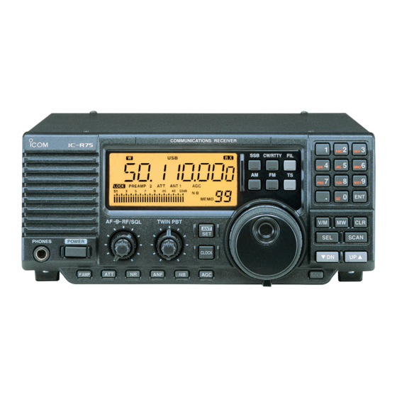
Icom IC-R75 Instruction Manual
Communications receiver
Hide thumbs
Also See for IC-R75:
- Service manual (51 pages) ,
- Instruction manual (47 pages) ,
- Price list (158 pages)
Table of Contents
Advertisement
Quick Links
Download this manual
See also:
Service Manual
Advertisement
Table of Contents

Subscribe to Our Youtube Channel
Related Manuals for Icom IC-R75


Summary of Contents for Icom IC-R75
- Page 1 INSTRUCTION MANUAL COMMUNICATIONS RECEIVER iR75...
-
Page 2: Explicit Definitions
NOTE injury, fire or electric shock. TRADEMARKS Icom, Icom Inc. and the Icom logo are registered trademarks of Icom Incorporated (Japan) in Japan, the United States, the United Kingdom, Germany, France, Spain, Russia and/or other countries. Microsoft and Windows are registered trademarks of Microsoft Corporation in the United States and other countries. -
Page 3: Precautions
• Connect the equipment into an outlet on a circuit different from that to which the receiver is connected. • Consult the dealer or an experienced radio/TV technician for help. Versions of the IC-R75 which display the “CE” symbol on the serial number label comply with the European harmonised standard ETS300 684 (EMC product standard for Commercially Available... -
Page 4: Supplied Accessories
SUPPLIED ACCESSORIES The receiver comes with the following accessories. Qty. q AC adapter (AD-55/A/S/V )* ........ 1 † w DC power cable (OPC-869)* ....... 1 e Fuse (FGB 3 A; internal use) ......1 r Fuse (FGB 3 A; for DC cable)* ......2 * Either AC adapter + 1 fuse (q, e) or DC power cable + 3 fuses (w, e, r) are supplied depending on versions. -
Page 5: Table Of Contents
TABLE OF CONTENTS IMPORTANT ............. i 6 MEMORY OPERATION ......21 – 24 EXPLICIT DEFINITIONS .......... i ■ Memory channels ........... 21 TRADEMARKS ............i ■ Memory channel selection ......21 PRECAUTIONS ............ii ■ Memory channel programming ...... 22 SUPPLIED ACCESSORIES ........ -
Page 6: Panel Description
PANEL DESCRIPTION ■ Front panel Speaker Function display (p. 5) COMMUNICATIONS RECEIVER CW/RTTY RF/SQL TWIN PBT SCAN PHONES POWER CLOCK P.AMP LOCK y CLOCK MODE SWITCH [CLOCK] (p. 28) q POWER SWITCH [POWER] Toggles between frequency indication and clock ➥ Push momentarily to turn power ON. indication when pushed. - Page 7 PANEL DESCRIPTION !1 MEMORY CHANNEL UP/DOWN SWITCHES !7 FILTER SWITCH [FIL] (pgs. 18, 19) [√ DN]/[UP ∫] (p. 21) ➥ Push momentarily to toggle between the pre- ➥ Select a memory channel. programmed normal, wide and narrow IF filters ➥ Select a set mode contents while in set mode. for the selected operating mode.
- Page 8 PANEL DESCRIPTION ■ Front panel (continued) Function display (p. 5) COMMUNICATIONS RECEIVER CW/RTTY RF/SQL TWIN PBT SCAN PHONES POWER CLOCK P.AMP LOCK @4 AGC SWITCH [AGC] (p. 16) !9 PREAMP SWITCH [P.AMP] (p. 16) ➥ Toggles the AGC (Automatic Gain Control) time Push to toggle between preamp-1 and preamp-2 constant fast and slow when pushed.
-
Page 9: Function Display
PANEL DESCRIPTION ■ Function display LSBUSBCW S-AMFM RTTY TIMER LOCK PREAMP F.AGC OFF BLANK BLANK 60dB N B VFO SCAN MEMO !0 !1 !2 !3 !4 !2 AGC INDICATORS (p. 16) q TIMER INDICATOR (p. 28) ➥ “AGC” appears when slow AGC time constant is Appears when power on/off timer or sleep timer is selected. -
Page 10: Rear Panel
AC adapter. r CI-V REMOTE CONTROL JACK [REMOTE] • Current of 1.5 A or greater is required. Allows connection to an Icom CI-V system transceiver or another receiver for the transceive DO NOT use a cigarette lighter socket as a function. -
Page 11: Installation And Connections
INSTALLATION AND CONNECTIONS ■ Grounding ■ Optional bracket and carrying handle To prevent accidents involving electr icity and interference from transceivers, ground the receiver D Mounting bracket through the [GND] terminal on the rear panel. An optional IC-MB5 MOBILE MOUNTING BRACKET available to install the radio under a table, on a wall, For best results, connect a heavy gauge wire or strap in a vehicle, etc. -
Page 12: Connections
INSTALLATION AND CONNECTIONS ■ Connections COMMUNICATIONS RECEIVER CW/RTTY HEADPHONES RF/SQL TWIN PBT SCAN PHONES POWER CLOCK P.AMP LOCK REMOTE (p. 9, 32) ANTENNA 2 ANTENNA 1 (p. 9) Used for computer control and transceive. Connect a long wire Connect a Yagi antenna; antenna;... -
Page 13: Antenna Connection
[LINE IN] jack 4.7 kΩ ■ Transceive function Icom CI-V transceivers or receivers can be connected * When a set frequency is out-of-range for one of the connected transceivers or receivers, the connected via the [REMOTE] jack. The frequency and mode radio’s frequency/mode does not change. -
Page 14: Fsk And Afsk (Sstv) Connections
• Intel i486DX4 processor or faster (Pentium MHz or faster recommended) • At least 16 MB RAM • At least 10 MB of hard disk space • At least 640 × 480 pixel, high color (16 bit) display Supplied RS-232C cable (OPC-743) IC-R75... -
Page 15: Frequency Setting
FREQUENCY SETTING ■ Read me first Therefore, when you want to keep a displayed The receiver uses memory channels for storage of frequency for later recall, you must program it into a frequencies (as well as mode, tuning steps, etc.). When turning power OFF or changing memory channels, memory channel by pushing [MW] for 2 sec. -
Page 16: Frequency Setting
FREQUENCY SETTING ■ Frequency setting Rotate the tuning dial to change the frequency. • The frequency changes in increments determined by the selected tuning step (see below). • When the lock function is activated (“LOCK” appears), the frequency cannot be changed via tuning dial. Push [TS] one or more times to select a quick tuning step. -
Page 17: Dial Lock Function
FREQUENCY SETTING D 1 MHz quick tuning step The quick tuning step function allows you to change Quick tuning step the frequency in 1 MHz steps when rotating the indicator tuning dial. Push [TS] one or more times until the 1 MHz tuning step indicator, “... -
Page 18: Receive Functions
RECEIVE FUNCTIONS ■ Mode selection The following modes are available in the IC-R75: OPERATING MODE SELECTION SSB (LSB/USB), CW, CW REV (CW reverse), FM, AM, RTTY and RTTY REV (RTTY reverse). CW/RTTY CW REV RTTY RTTY REV ➥ Push [SSB] to toggle between LSB and USB. -
Page 19: Twin Pbt Operation
RECEIVE FUNCTIONS ■ Twin PBT operation T h e t w i n P B T ( Pa s s b a n d Tu n i n g ) f u n c t i o n • [TWIN PBT] should normally be set to the center electronically narrows the IF passband widths positions when there is no interference. -
Page 20: Preamp
RECEIVE FUNCTIONS ■ Preamp The preamp amplifies received signals in the front end circuit to improve the S/N ratio and sensitivity. Turn this function ON when receiving weak signals. PREAMP 1 BLANK BLANK 60dB ➥ Push [P.AMP] to toggle between preamp-1 and preamp-2 or turn the preamp OFF. -
Page 21: Cw Reverse Mode
RECEIVE FUNCTIONS ■ CW reverse mode CW-R (CW Reverse) mode receives CW signals with • Receive audio tone response a reverse side CW carrier point like that of LSB and USB modes. 1/3 octave 1/2 octave Use when interfering signals are near a desired Push for 2 sec. -
Page 22: Filter Selection
RECEIVE FUNCTIONS ■ Filter selection The filter selection switches the IF passband width as shown in the table at right. Passband Recommended Filter width selectivity The filter selection is automatically memorized in FL-100 500 Hz/–6 dB CW-N, RTTY-N each mode. FL-101 250 Hz/–6 dB CW-N... -
Page 23: Filter Set Mode
RECEIVE FUNCTIONS ■ Filter set mode When an optional filter is installed, set the optional filters in filter set mode. Optional filters are not •9 MHz normal filter selection selected by default. D Optional filter setting q Push [FIL] for 2 sec. to enter filter set mode. •... -
Page 24: Optional Noise Reduction Function
RECEIVE FUNCTIONS ■ Optional noise reduction function optional UT-106 When an optional UT-106 is installed (DSP appears in the function display), noise reduction function can be used. Noise reduction OFF Noise reduction activated Noise components Desired The noise reduction function reduces noise signal (CW) components and picks out desired signals which are buried in noise. -
Page 25: Memory Operation
MEMORY OPERATION ■ Memory channels All 101 memory channels are tuneable which means The receiver has 101 memory channels. The memory the programmed frequency can be tuned temporarily mode is very useful for quickly changing to often-used frequencies. with the tuning dial, etc. in memory mode. MEMORY TRANSFER OVER-... -
Page 26: Memory Channel Programming
MEMORY OPERATION ■ Memory channel programming Memory channel programming can be preformed either in VFO mode or in memory mode. D Programming in VFO mode [EXAMPLE]: Programming 7.088 MHz/LSB into memory channel 12. q Set the desired frequency and operating mode in VFO mode. -
Page 27: Frequency Transferring
MEMORY OPERATION ■ Frequency transferring The frequency and operating mode in a memory Frequency transferring can be performed in either channel can be transferred to the VFO. VFO mode or memory mode. D Transferring in VFO mode TRANSFERRING EXAMPLE IN VFO MODE Operating frequency : 21.320 MHz/USB (VFO) This is useful for transferring programmed contents... -
Page 28: Memory Names
MEMORY OPERATION ■ Memory names All memory channels (including scan edges) can be r Push [ENT] to edit memory channel name. tagged with alphanumeric names of up to 8 characters • A cursor appears and blinks. each. • Memory channel names of blank channels cannot be edited. -
Page 29: Scans
SCANS ■ Scan types PROGRAMMED SCAN/AUTO MEMORY WRITE SCAN MEMORY SCAN Repeatedly scans between two scan edge frequencies Repeatedly scans all programmed memory channels. (scan edge memory channels P1 and P2). Auto memory S (select) BLANK write scan automatically memorizes paused frequencies into memory channels 80 to 99. -
Page 30: Programmed Scan Operation
SCANS ■ Programmed scan operation q Select VFO mode with [V/M]. t When the scan detects a signal, the scan stops, w Select the desired operating mode. pauses or ignores it depending on the resume • The operating mode can also be changed while setting and the squelch condition. -
Page 31: Scan]
SCANS ■ Priority watch operation Priority watch checks for signals on a frequency every 5 sec. while operating on a VFO frequency. y When a signal is received on a watch channel, the function display shows the watch channel and q Select memory mode with [V/M]. -
Page 32: Clock And Timers
CLOCK AND TIMERS ■ Setting the current time The receiver has a built-in 24-hour clock with power- e Set the current time using the tuning dial; or push off and power-on timer functions. This is useful when keypad using 4-digit 24 hour system. logging SWL’s, BCL’s and so on. -
Page 33: Setting Power-Off Time
CLOCK AND TIMERS ■ Setting power-off time The receiver can be set to turn OFF automatically at r Set the desired time using the tuning dial; or push a specified time. keypad using 4-digit 24 hour system. t Push [ENT] to set the time. q Push [CLOCK] to select clock indication mode. -
Page 34: Set Mode
SET MODE ■ Set mode description Set mode is used for programming infrequently changed values or conditions of functions. D Set mode operation q Push [ SET] to enter the set mode. (ANT) w Push [UP Y] or [Z DN] to select the desired item. e Set the desired condition using the tuning dial. - Page 35 SET MODE • Scan resume This item sets the scan resume function ON or OFF. • “on” scan resumes 10 sec. after stopping on a signal (or 2 sec. after a signal disappears) • “oF” scan does not resume after stopping on a signal. See p.
- Page 36 • CI-V address To distinguish equipment, each CI-V transceiver or receiver has its own Icom standard address in hexadecimal code. The IC-R75’s address is 5Ah. When 2 or more IC-R75’s are connected to an optional CT-17 , rotate the CI-V LEVEL CONVERTER tuning dial to select a different address for each IC-R75 in the range 01h to 7Fh.
-
Page 37: Set Mode
SET MODE • Speech speed When the optional UT-102 VOICE SYNTHESIZER UNIT is installed, you can select between faster or slower synthesizer output. See p. 34 for unit installation. • Speech S-level When the optional UT-102 VOICE SYNTHESIZER UNIT is installed, you can have signal level, frequency, mode and current time announcement. -
Page 38: Option Installations
OPTION INSTALLATIONS ■ Opening the receiver’s case e Remove the 2 screws from the bottom of the receiver, slide the cover backward, then remove the bottom cover. Follow the case and cover opening procedures shown here when you want to install an optional unit or adjust an internal unit, etc. -
Page 39: Ut-106 Dsp Unit
J1221 ■ Optional IF filters D Installation Several IF filters are available for the IC-R75. You can install 1 filter for both 9 MHz and 455 kHz IF. q Remove the top cover as shown on the opposite Choose appropriate filter for your operating needs. -
Page 40: Maintenance
If you are not able to locate the cause of a problem The following chart is designed to help you correct or solve it through the use of this chart, contact your problems which are equipment malfunctions. nearest Icom Dealer or Service Center. PROBLEM POSSIBLE CAUSE SOLUTION REF. -
Page 41: Fuse Replacement
CAUTION: DISCONNECT the DC power cable 3 A fuse from the receiver when changing a fuse. The IC-R75 has 2 types of fuses installed for receiver protection. • DC power cable fuses FGB 3 A • Circuitry fuse... -
Page 42: Specifications
SPECIFICATIONS D General D Receiver • Frequency coverage : 0.03–60.000000 MHz* • Receive system : Triple-conversion * 0.03–29.999999 MHz only for Asia version; 0.03– superheterodyne system 29.999999 and 50.0–52.0 MHz for Denmark version; • Intermediate frequencies: specifications guaranteed 0.1–29.99 MHz and 50–54 MHz only Mode (MHz) -
Page 43: Options
Approved Icom optional equipment is designed for optimal performance when used with an Icom receiver. Icom is not responsible for the destruction or damage to an Icom receiver in the event the Icom receiver is used with equipment that is not manufactured or approved by Icom. -
Page 44: Control Command
CI-V LEVEL CONVERTER RS-232C port. The Icom Communications Interface-V (CI-V) controls the following functions of the receiver. Up to 4 Icom CI-V transceivers or receivers can be connected to a PC equipped with an RS-232C port. ct-17 See p. 32 for setting the CI-V condition using set mode. -
Page 45: Command Table
CONTROL COMMAND • Command table Command Sub command Description Command Sub command Description — Send frequency data Attenuator OFF Attenuator ON Same as Send mode data command 06 Select [ANT1] Select [ANT2] — Read band edge frequencies — Read operating frequency Announce with voice synthesizer (00=all data;... - Page 46 CONTROL COMMAND • CI-V data example 1 Reading/sending memory contents: y Attenuator q Memory channel u Preamp Preamp 1 w Select memory ch select ch i Antenna selection ANT1 e Receive frequency 12.345678 MHz o Memory name DXSPOT 1 r Receive mode NOTE: When reading data, w –...
-
Page 47: Control Command
CONTROL COMMAND • CI-V data example 3 Reading/sending set mode contents: q Set mode number 21 (backlighting) w Set data Set backlighting to a little on F E F E 5 A E 0 1 A 0 2 2 1 0 1 the brighter side (180) NOTE: When reading data, w is not required. - Page 48 A-5580H-1EX-t Printed in Japan © 1999–2009 Icom Inc. 1-1-32 Kamiminami, Hirano-ku, Osaka 547-0003, Japan Printed on recycled paper with soy ink.
Need help?
Do you have a question about the IC-R75 and is the answer not in the manual?
Questions and answers