Icom IC-R75 Instruction Manual
Communications receiver
Hide thumbs
Also See for IC-R75:
- Service manual (51 pages) ,
- Instruction manual (47 pages) ,
- Price list (158 pages)
Table of Contents
Advertisement
Quick Links
Advertisement
Table of Contents

Related Manuals for Icom IC-R75


Summary of Contents for Icom IC-R75
- Page 1 INSTRUCTION MANUAL COMMUNICATIONS RECEIVER iR75...
-
Page 2: Explicit Definitions
* Either AC adapter + 1 fuse (q, e) or DC power cable + 3 fuses (w, e, r) are supplied depending on versions. Versions of the IC-R75 which display the “CE” symbol on the serial number seal comply with the European har- monised standard ETS300 684 (EMC product standard for Commercially Available Amateur Radio Equipment). -
Page 3: Table Of Contents
IMPORTANT ... i EXPLICIT DEFINITIONS ... i PRECAUTIONS ... i SUPPLIED ACCESSORIES ... i 1 TABLE OF CONTENTS ... 1 2 PANEL DESCRIPTION ... 2 – 6 Front panel ... 2 Function display ... 5 Rear panel ... 6 3 INSTALLATION AND CONNECTIONS ... 7 – 10 Grounding ... -
Page 4: Panel Description
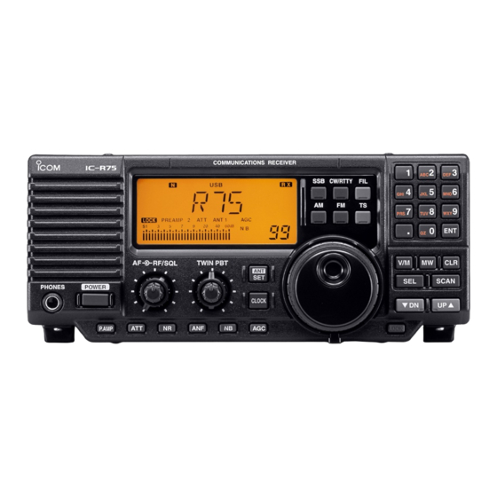
PANEL DESCRIPTION Front panel Speaker PHONES POWER q POWER SWITCH [POWER] Push momentarily to turn power ON. • Turn the optional DC power supply ON in advance. Push for 2 sec. to turn power OFF. w HEADPHONE JACK [PHONES] (p. 8) Accepts headphones. - Page 5 !1 MEMORY CHANNEL UP/DOWN SWITCHES [√ √ DN]/[UP ∫ ∫ ] (p. 21) Select a memory channel. Select a set mode contents while in set mode. Select a timer or time indication while in clock in- dication. Select a filter set mode contents while in filter set mode.
- Page 6 PANEL DESCRIPTION Front panel (continued) PHONES POWER !9 PREAMP SWITCH [P.AMP] (p. 16) Push to toggle between preamp-1 and preamp-2 or turn the preamp OFF. @0 ATTENUATOR SWITCH [ATT] (p. 16) Push to toggle the 20 dB attenuator function ON and OFF.
-
Page 7: Function Display
Function display TIMER LOCK q TIMER INDICATOR (p. 28) Appears when power on/off timer or sleep timer is in use. w DSP UNIT INDICATOR (p. 35) Appears when an optional UT-106 stalled. e AUTOMATIC NOTCH FILTER INDICATOR (p. 20) Appears when the optional automatic notch filter is in use. -
Page 8: Panel Description ................................... 2
CI-V REMOTE CONTROL JACK [REMOTE] Allows connection to an Icom CI-V system trans- ceiver or another receiver for the transceive func- tion. Also connects to a PC with several receivers... -
Page 9: Installation And Connections
INSTALLATION AND CONNECTIONS Grounding To prevent accidents involving electricity and interfer- ence from transceivers, ground the receiver through the [GND] terminal on the rear panel. For best results, connect a heavy gauge wire or strap to a long earth-sunk copper rod. Make the distance be- tween the [GND] terminal and ground as short as pos- sible. -
Page 10: Connections
INSTALLATION AND CONNECTIONS Connections HEADPHONES REMOTE (p. 9, 32) Used for computer control and transceive. MUTE CONTROL JACK (p. 6) RECORDER/ RECORDER CONTROL (p. 9) RS-232C JACK (p. 10) COMMUNICATIONS RECEIVER RF/SQL TWIN PBT PHONES POWER P.AMP ANTENNA 2 Connect a long wire antenna;... -
Page 11: Antenna Connection
(1 A/DC max.) [AUX IN] or [LINE IN] jack Transceive function Icom CI-V transceivers or receivers can be connected via the [REMOTE] jack. The frequency and mode be- come the same* when either radio is changed. IC-R75 [REMOTE] Be sure the “CIV TRn”... -
Page 12: Installation And Connections ......... 7
MHz or faster recommended) • At least 16 MB RAM • At least 10 MB of hard disk space • At least 640 480 pixel, high color (16 bit) display Supplied RS-232C cable (OPC-743) IC-R75 Personal computer ® ® ® 95 or Microsoft Windows ®... -
Page 13: Frequency Setting
Read me first The receiver uses memory channels for storage of fre- quencies (as well as mode, tuning steps, etc.). When turning power OFF or changing memory channels, the previously displayed frequency cannot be recalled un- less it has been stored into a memory channel. 60dB V F O “BLANK”... -
Page 14: Frequency Setting
FREQUENCY SETTING Frequency setting Rotate the tuning dial to change the frequency. • The frequency changes in increments determined by the selected tuning step (see below). • When the lock function is activated (“LOCK” appears), the frequency cannot be changed via tuning dial. Push [TS] one or more times to select a quick tuning step. -
Page 15: Dial Lock Function
D 1 MHz quick tuning step The quick tuning step function allows you to change the frequency in 1 MHz steps when rotating the tun- ing dial. Push [TS] one or more times until the 1 MHz tuning step indicator, “",” appears above the 1 MHz indica- tor. -
Page 16: Receive Functions
RECEIVE FUNCTIONS Mode selection The following modes are available in the IC-R75: SSB (LSB/USB), CW, CW REV (CW reverse), FM, AM, S-AM (Synchronous detection AM), RTTY and RTTY REV (RTTY reverse). Push [SSB] to toggle between LSB and USB. Push [CW/RTTY] momentarily to toggle between CW and RTTY. -
Page 17: Twin Pbt Operation
Twin PBT operation The twin PBT (Passband Tuning) function electroni- cally narrows the IF passband widths to reduce inter- ference. Moving both [TWIN PBT] controls to the same position shifts the IF. Variable range depends on the filter selection. ±1.29 kHz in 15 Hz steps and ±258 kHz in 3 Hz steps are available. -
Page 18: Preamp
RECEIVE FUNCTIONS Preamp The preamp amplifies received signals in the front end circuit to improve the S/N ratio and sensitivity. Turn this function ON when receiving weak signals. Push [P.AMP] to toggle between preamp-1 and preamp-2 or turn the preamp OFF. Attenuator The attenuator prevents desired signals from distort- ing when very strong signals are near the desired fre-... -
Page 19: Cw Reverse Mode
CW reverse mode CW-R (CW Reverse) mode receives CW signals with a reverse side CW carrier point like that of LSB and USB modes. Use when interfering signals are near a desired signal and you want to change the interference tone. q Push [CW/RTTY] once or twice to select CW mode. -
Page 20: Filter Selection
RECEIVE FUNCTIONS Filter selection The filter selection switches the IF passband width as shown in the table at right. The filter selection is automatically memorized in each mode. q Select the desired mode with the mode switches. w Push [FIL] one or more times to select the desired filter combination. -
Page 21: Filter Set Mode
Filter set mode When an optional filter is installed, set the optional fil- ters in filter set mode. Optional filters are not selected by default. D Optional filter setting q Push [FIL] for 2 sec. to enter filter set mode. •... -
Page 22: Optional Noise Reduction Function
RECEIVE FUNCTIONS Optional noise reduction function When an optional UT-106 is installed (DSP appears in the function display), noise reduction function can be used. The noise reduction function reduces noise compo- nents and picks out desired signals which are buried in noise. -
Page 23: Memory Operation
Memory channels The receiver has 101 memory channels. The memory mode is very useful for quickly changing to often-used frequencies. MEMORY MEMORY CHANNEL CHANNEL NUMBER Regular memory 1–99 channels Scan edge memory P1, P2 channels Memory channel selection D Using the [UP Y] or [Z DN] keys q Push [V/M] to select memory mode. -
Page 24: Memory Channel Programming
MEMORY OPERATION Memory channel programming Memory channel programming can be preformed ei- ther in VFO mode or in memory mode. D Programming in VFO mode q Set the desired frequency and operating mode in VFO mode. w Push [UP Y] or [Z DN] several times to select the desired memory channel. -
Page 25: Frequency Transferring
Frequency transferring The frequency and operating mode in a memory chan- nel can be transferred to the VFO. D Transferring in VFO mode This is useful for transferring programmed contents to VFO. q Select VFO mode with [V/M]. w Select the memory channel to be transferred with [UP Y] or [Z DN]. -
Page 26: Memory Names
MEMORY OPERATION Memory names All memory channels (including scan edges) can be tagged with alphanumeric names of up to 8 charac- ters each. Letters (capitals except ‘o’), numerals and spaces can be used. Numerals can only be used for the 7th and 8th digits. -
Page 27: Scans
Scan types PROGRAMMED SCAN/AUTO MEMORY WRITE SCAN Repeatedly scans between two scan edge frequencies (scan edge memory channels P1 and P2). Auto memory write scan automatically memorizes paused frequencies into memory channels 80 to 99. Scan edge P1 or P2 Scan Jump This scan operates in VFO mode. -
Page 28: Programmed Scan Operation
SCANS Programmed scan operation q Select VFO mode with [V/M]. w Select the desired operating mode. • The operating mode can also be changed while scan- ning. e Set [RF/SQL] open or closed. • See previous page for scan condition. •... -
Page 29: Scans ........................................................ 25
Priority watch operation Priority watch checks for signals on a frequency every 5 sec. while operating on a VFO frequency. q Select memory mode with [V/M]. w Select the desired memory channel to be watched with [UP Y] or [Z DN]. e Select VFO mode. -
Page 30: Clock And Timers
CLOCK AND TIMERS Setting the current time The receiver has a built-in 24-hour clock with power- off and power-on timer functions. This is useful when logging SWL’s, BCL’s and so on. q Push [CLOCK] to select clock indication mode. • Current time and “CL” appear. w Push [ SET] for 2 sec. -
Page 31: Setting Power-Off Time
Setting power-off time The receiver can be set to turn OFF automatically at a specified time. q Push [CLOCK] to select clock indication mode. w Push [UP Y] or [Z DN] twice to select power-off timer screen. • Power-off time and “oF” appear. e Push [ SET] for 2 sec. -
Page 32: Set Mode
SET MODE Set mode description Set mode is used for programming infrequently changed values or conditions of functions. D Set mode operation q Push [ SET] to enter the set mode. (ANT) w Push [UP Y] or [Z DN] to select the desired item. e Set the desired condition using the tuning dial. -
Page 33: Scan Resume
• Scan resume This item sets the scan resume function ON or OFF. • “on” scan resumes 10 sec. after stopping on a signal (or 2 sec. after a signal disappears) • “oF” scan does not resume after stopping on a signal. See p. - Page 34 To distinguish equipment, each CI-V transceiver or re- ceiver has its own Icom standard address in hexa- decimal code. The IC-R75’s address is 5Ah. When 2 or more IC-R75’s are connected to an op- tional CT-17 , rotate the tuning...
-
Page 35: Set Mode .................................................. 30
• Speech speed When the optional UT-102 VOICE SYNTHESIZER UNIT installed, you can select between faster or slower syn- thesizer output. See p. 34 for unit installation. • Speech S-level When the optional UT-102 VOICE SYNTHESIZER UNIT installed, you can have signal level, frequency, mode and current time announcement. -
Page 36: Option Installations
OPTION INSTALLATIONS Opening the receiver’s case Follow the case and cover opening procedures shown here when you want to install an optional unit or adjust an internal unit, etc. CAUTION: DISCONNECT the DC power cable from the receiver before performing any work on the receiver. -
Page 37: Ut-106 Dsp Unit
Return the shielding plate, top cover and bottom cover to their original positions. Optional IF filters Several IF filters are available for the IC-R75. You can install 1 filter for both 9 MHz and 455 kHz IF. Choose appropriate filter for your operating needs. -
Page 38: Maintenance
[POWER] If you are not able to locate the cause of a problem or solve it through the use of this chart, contact your near- est Icom Dealer or Service Center. POSSIBLE CAUSE the [NR] level is set too high. -
Page 39: Maintenance ........................................ 36
CAUTION: DISCONNECT the DC power cable from the receiver when changing a fuse. The IC-R75 has 2 types of fuses installed for receiver protection. • DC power cable fuses ... FGB 3 A • Circuitry fuse ... FGB 3 A CIRCUITRY FUSE REPLACEMENT The 13.8 V DC from the DC power cable is applied to... -
Page 40: Specifications
SPECIFICATIONS D General • Frequency coverage : 0.03–60.000000 MHz* * 0.03–29.999999 MHz only for Asia version; 0.03–29.999999 and 50.0–52.0 MHz for Denmark version; specifications guaranteed 0.1–29.99 MHz and 50–54 MHz only • Mode : USB, LSB, CW, RTTY, AM, S-AM, FM •... -
Page 41: Options
FL-100, FL-101, FL-103, FL-223 and FL-232 9 MHz FILTERS • FL-100: 500 Hz/–6 dB (CW/RTTY nar.) • FL-101: 250 Hz/–6 dB (CW nar.) • FL-103: 2.8 kHz/–6 dB (SSB wide) • FL-223: 1.9 kHz/–6 dB (SSB nar.) • FL-232: 350 Hz/–6 dB (RTTY/CW nar.) MB-23 CARRYING HANDLE Carrying handle, convenient for portable operation. -
Page 42: Control Command
RS-232C port. The Icom Communi- cations Interface-V (CI-V) controls the following func- tions of the receiver. Up to 4 Icom CI-V transceivers or receivers can be connected to a personal computer equipped with an RS-232C port. See p. 32 for setting the CI-V condition using set mode. -
Page 43: Command Table
• Command table Command Sub command Description — Send frequency data Same as Send mode data command 06 — Read band edge frequencies — Read operating frequency Same as Read operating mode command 06 — Set frequency data Set LSB Set USB Set AM Set CW... - Page 44 CONTROL COMMAND • CI-V data example 1 Reading/sending memory contents: q Memory channel w Select memory ch select ch e Receive frequency 12.345678 MHz r Receive mode t IF filter Narrow F E F E 5 A E 0 1 A 0 0 0 0 3 9 Mode Data Data...
- Page 45 • CI-V data example 3 Reading/sending set mode contents: q Set mode number 21 (backlighting) w Set data Set backlighting to a little on the brighter side (180) NOTE: When reading data, w is not required. • Set mode data table Set mode No (q) Set mode item RF/squelch control...
- Page 46 Count on us! A-5580H-1EX-e Printed in Japan 6-9-16 Kamihigashi, Hirano-ku, Osaka 547-0002 Japan © 1999 Icom Inc.
Need help?
Do you have a question about the IC-R75 and is the answer not in the manual?
Questions and answers