Husqvarna Automower 210 C Operator's Manual
Hide thumbs
Also See for Automower 210 C:
- Technical manual (120 pages) ,
- Operator's manual (50 pages) ,
- Quick manual (2 pages)
Table of Contents
Advertisement
Advertisement
Table of Contents

Related Manuals for Husqvarna Automower 210 C


Summary of Contents for Husqvarna Automower 210 C
- Page 1 h u sqvarna auTOMOWE r ® 210 C OpE r aTOr’s Man ual...
-
Page 2: Table Of Contents
TABLE OF CONTENTS 1. Introduction and safety .............. 1.1 Introduction ..................® 1.2 Symbols on Automower ............1.3 Symbols in the Operator’s Manual .......... 1.4 Safety instructions ................ 2. Presentation .................. ® 2.1 Automower , what’s what? ............. ® 2.2 Function of Automower ............ - Page 3 TABLE OF CONTENTS Husqvarna AB has a policy of continuous product development and therefore reserves the right to modify the design and appearance and function of products without prior notice. This Operator's Manual deals with version 2.7x of the mower’s control program.
-
Page 4: Introduction And Safety
1.1 Introduction Congratulations on your choice of an exceptionally high quality product. To get the best results from your Husqvarna Automower ® requires knowledge of its function. This Operator's manual contains important information about the mower, how you install it and how you use it. -
Page 5: Symbols On Automower
1. INTRODUCTION AND SAFETY 1.2 Symbols on Automower ® These symbols can be found on the lawn mover. Study them carefully so you understand their significance. • Read through the Operator’s Manual carefully and understand the content before using your Automower ®... -
Page 6: Symbols In The Operator's Manual
1. INTRODUCTION AND SAFETY 1.3 Symbols in the Operator’s Manual These symbols can be found in the Operator’s Manual. Study them carefully so you understand their significance. • Inspection and/or maintenance must be carried out with the main switch set to OFF . •... -
Page 7: Safety Instructions
® is moved to the ON position and the correct PIN code has been entered. • Husqvarna AB does not guarantee full compatibility between Automower ® and other types of wireless systems such as remote controls, radio transmitters, buried electric animal fencing or similar. - Page 8 1. INTRODUCTION AND SAFETY Transport The original packaging should be used when transporting Automower over long distances. ® To safely move from or within the working area: Move the main switch to the OFF position if you intend to carry the mower. Carry the mower by the handle at the rear of the mower.
-
Page 9: Presentation
2. PRESENTATION 2. Presentation This chapter contains information you should be aware of when planning the installation. An installation of Husqvarna Automower ® comprises three main components: Automower ® , an automatic lawn mower that mows the lawn by moving in an irregular pattern. The mower is powered by a maintenance-free battery. -
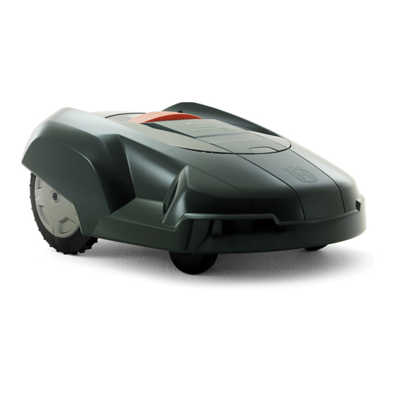
Page 10: Automower , What's What
2. PRESENTATION 2.1 Automower , what’s what? ® The numbers in the picture correspond to: Cutting height adjustment cover 14. Blade disc Catch button to open the cutting height adjustment 15. Loop wire for boundary wire cover 16. Connection to boundary wire Front wheel 17. -
Page 11: Function Of Automower
2. PRESENTATION 2.2 Function of Automower ® Capacity Automower ® is recommended for lawns up to 500 m The size of the working area the mower can handle depends on how much it is used. The larger the lawn the more occasions per week the Automower ®... - Page 12 2. PRESENTATION When there is a risk of thunder Automower ® should not stand in the charging station. When there is a risk of a thunder storm, the 230 V plug should be removed from the mains socket and the boundary wire disconnected from the charging station.
-
Page 13: One Automower In Several Gardens
2. PRESENTATION A four digit PIN code must be chosen and entered when the main switch is set in the ON position for the first time. (see page 30). The chosen PIN code must then be entered each time the mower is started. If the mower does not start within 20 seconds the PIN code must be re-entered until the mower starts. -
Page 14: Installation
3. INSTALLATION 3. Installation This chapter describes how you install Husqvarna Automower ® . Before starting the installation read the previous chapter 2. Presentation. Read the whole of this chapter too before starting the installation. How the installation is made also affects how Automower ®... -
Page 15: Installation Of The Loop Generator/Charger
3. INSTALLATION 3.2 Installation of the loop generator/charger The loop generator/charger must be placed where it is well ventilated and is not exposed to direct sunlight. The mower's battery is spared if it is charged in the lowest possible ambient temperature. It is also beneficial if the transformer can be placed under a roof. -
Page 16: Charging The Battery
3. INSTALLATION 3.3 Charging the battery Automower is supplied with an uncharged battery. As ® soon as the loop generator/charger is connected, it is possible to charge the mower. Set the main switch to the ON position and leave the cover for the control panel open. Connect the charger cable from the loop generator/charger to the charger contact on the mower. - Page 17 3. INSTALLATION Best position for the boundary wire The boundary wire should be laid so it: • Forms a loop around the working area for Automower ® . Only an original boundary wire must be used. This is tinned and has a high quality insulation to withstand the dampness in the ground.
- Page 18 3. INSTALLATION Boundaries for the working area If a high obstacle, for example a wall or fence, borders the working area, the boundary wire should be laid 35 cm from the obstacle. This will prevent Automower ® from colliding with the obstacle and reduce body wear.
- Page 19 3. INSTALLATION Boundaries within the working area Use the boundary wire to demarcate areas inside the working area by creating islands around obstacles that can not withstand a collision, for example, flower beds and fountains. Run the cable out to the area, route it around the area to be demarcated and then back along the same route.
- Page 20 3. INSTALLATION Secondary areas It is recommended to create a secondary area when the working area is made up of two areas that are joined by a passage where the distance between the Secondary area boundary wires is less than 60 cm. Run the boundary wire then around the secondary area so that it forms an island outside of the main area.
- Page 21 3. INSTALLATION Automower ® can mow areas inside the working area that slope up to 35 cm per distance metre (35 %). Areas that slope more must be demarcated by the boundary wire. When any part of the working area's boundary slopes more than 10 cm per distance metre (10 %), the boundary wire must be routed about...
- Page 22 3. INSTALLATION • Make sure to lay the boundary wire tight to the ground and secure the staples close together with approximately 75 cm between each staple. The wire must generally lie close to the ground so, as not to be cut off before the grass roots have grown over it.
-
Page 23: Connecting The Boundary Wire
3. INSTALLATION Joining the boundary wire If the boundary wire is not long enough and needs to be spliced: Use original solderless coupler. It is waterproof and gives a reliable electrical connection. To splice: Insert both cable ends in the coupler. Now press down the button on top of the connector fully. -
Page 24: Checking The Installation
3. INSTALLATION Cut off any surplus boundary wire. Cut 1 - 2 cm above respective connectors. Attach the connector to the contact pin on the loop generator/charger. 3.6 Checking the installation Check the loop signal by looking to see what indication the green LED on the loop generator/charger is giving. -
Page 25: Linking Automower To The Loop Generator/Charger
3. INSTALLATION 3.7 Linking Automower to the loop ® generator/charger Connect the loop generator/charger charging cable to the mower's charger contact. At most the mower may be two metres from the working area's boundary wire and the loop generator/charger must be connected to the mains supply. -
Page 26: Use
Press the STOP button to open the control panel cover on Husqvarna Automower ® Set the main switch to the ON position. Enter the PIN code, confirm with the YES button. -
Page 27: Restart
4. USE 4.3 Restart To start: Enter the PIN code. Press the YES button. Close the control panel cover. 4.4 Switching off Automower ® Press the STOP button. Set the main switch to the OFF position. Always switch off Automower ®... -
Page 28: Adjusting The Cutting Height
4. USE 4.6 Adjusting the cutting height The cutting height can be varied from MIN (2 cm) to MAX (6 cm). If the grass is long it is appropriate to let Automower ® start mowing at the MAX cutting height. Once the grass is shorter, you can gradually lower the cutting height. -
Page 29: Changing The Pin Code
4. USE 4.7 Changing the PIN code To change the PIN code on the mower: Connect the loop generator/charger charging cable to the mower's charger contact. At most the mower may be two metres from the working area's boundary wire and the loop generator/charger must be connected to the mains supply. -
Page 30: Sounds
4. USE 4.9 Sounds The mower indicates the operating status and all input with audio signals as set out below. Sound Significance 5 beeps over 2 seconds Starting blade disc Short click sound A button on the keypad has been pressed One long beep Blade disc blocked Incorrect input... -
Page 31: Control Panel
5. CONTROL PANEL 5. Control panel The control panel on Husqvarna Automower ® consists of indicator lamps and a keypad. All information is shown through the indicator lamps and all input is done using the buttons. The control panel consists of three groups of buttons: select, numbers and main switch, and indicator lamps.. -
Page 32: Main Switch
5. CONTROL PANEL 5.3 Main switch Set the main switch in the ON position to start Automower ® Set the main switch in the OFF position when you are not using the mower or if you want to work on the blade disc. When the main switch is set in the OFF position the motors on the mower cannot start. -
Page 33: Garden Example
6. GARDEN EXAMPLE 6. Garden example - Proposed installation An number of installations of Husqvarna Automower in different types of gardens are shown and ® explained in this chapter. See the examples as pointers for how to make the installation in your garden as good as possible. - Page 34 6. GARDEN EXAMPLE Proposals for installation Garden with a steep incline (30 %) that divides the garden into two areas, area: 400 m . If the mowing result between the areas is uneven, the garden can ideally be divided into two zones The mower may find it difficult to climb steep inclines, consequently zone 2 a garden with steep inclines can be mown...
-
Page 35: Maintenance
7. MAINTENANCE 7. Maintenance Check and clean Husqvarna Automower ® regularly and replace worn parts if necessary to improve operating reliability and to ensure a longer service life. For further information on cleaning, see 7.4 Cleaning on page 39. During the initial period Automower is used the blade ®... -
Page 36: Winter Storage
7. MAINTENANCE 7.2 Winter storage Automower ® Automower must be carefully cleaned before winter ® storage, see 7.4 Cleaning on page 39. Automower ® should not be continuously charged during the winter. Charge the battery fully before winter storage. Turn the main switch to the OFF position. -
Page 37: Cleaning
7. MAINTENANCE 7.4 Cleaning It is important to keep Automower clean. A mower ® with a large amount of clippings negotiates slopes very poorly. It is recommended to clean using a brush and a spray with water. IMPORTANT INFORMATION Never use a high-pressure washer or even running water to clean the Automower ®... -
Page 38: Replacing The Blades
Contact your dealer for further information. There are several different types of mower blades to choose from as accessories, with different features. Use Husqvarna AB approved blades only, see the table. Please contact your dealer for more information. Blade type... -
Page 39: Transport And Moving
7. MAINTENANCE Blade type Quantity/Packaging Part number Carbon steel 535 13 87-02 (two-toothed) 535 13 88-02 535 12 78-02 Carbon steel 522 85 16-02 (two-toothed, turnable, extra robust) 522 85 17-02 522 85 18-02 To replace the blades: Set the main switch to the OFF position. Wear protective gloves. -
Page 40: Trouble Shooting
8. Trouble shooting 8.1 Fault messages A number of fault messages that can be shown by the red Fault indicator lamp on Husqvarna Automower ® are shown below. The fault message is interpreted by reading how the lamp flashes. The lamp flashes one to five times in quick succession and then goes out for 2 seconds. - Page 41 8. TROUBLE SHOOTING Flashes Fault message Cause Action No loop signal If this occurs in isolated Try moving the boundary wire. areas it may be due to interference from metallic objects (perimeter fence, reinforcement bar) or buried cables in the vicinity.
-
Page 42: Fault Symptom
8. TROUBLE SHOOTING 8.2 Fault symptom If your Automower does not work correctly, follow the trouble shooting guide below. If the fault persists; ® contact your dealer. Symptom Cause Action Uneven mowing Automower works too few hours per Increase the mowing time. ®... -
Page 43: Technical Data
9. TECHNICAL DATA 9. Technical data Data Automower 210 C ® Dimensions Length 76 cm Width 55 cm Height 30 cm Weight 9.1 kg Electrical system Battery NiMH special battery 18V / 3Ah Transformer 230V / 24V Power consumption Maximum 9 kWh/month, mowing three times a week Noise emissions Measured noise level... -
Page 44: Environmental Information
11. EU declaration of conformity EU Declaration of Conformity (only applies to Europe) Husqvarna AB, SE-561 82 Huskvarna, Sweden, tel.: +46-36-146500, hereby declares that robotic lawnmower Husqvarna Automower ® 210 C from 2009's serial numbers and onwards (the year is... - Page 45 11. EU DECLARATION OF CONFORMITY Serial number: ___________________________________ Personal code: ___________________________________ Dealer __________________________________________ Dealer’s telephone number: ________________________ 46 - English...
- Page 46 ORIGINAL INSTRUCTIONS AUTOMOWER is a trademark owned by Husqvarna AB. Copyright © 2010 HUSQVARNA. All rights reserved. 115 27 61-26...
Need help?
Do you have a question about the Automower 210 C and is the answer not in the manual?
Questions and answers