Table of Contents
Advertisement
Quick Links
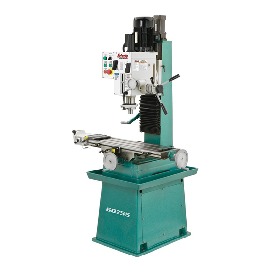
MODEL G0755
HEAVY-DUTY MILL/DRILL
w/STAND & POWER FEED
OWNER'S MANUAL
(For models manufactured since 1/13)
Copyright © ApriL, 2013 By grizzLy industriAL, inC.
WARNING: NO PORTION OF THIS MANUAL MAY bE REPRODUcED IN ANY SHAPE
OR FORM WITHOUT THE WRITTEN APPROVAL OF GRIzzLY INDUSTRIAL, INc.
#ts15627 printed in ChinA
Advertisement
Table of Contents

Related Manuals for Grizzly G0755


Summary of Contents for Grizzly G0755
- Page 1 OWNER'S MANUAL (For models manufactured since 1/13) Copyright © ApriL, 2013 By grizzLy industriAL, inC. WARNING: NO PORTION OF THIS MANUAL MAY bE REPRODUcED IN ANY SHAPE OR FORM WITHOUT THE WRITTEN APPROVAL OF GRIzzLY INDUSTRIAL, INc. #ts15627 printed in ChinA...
- Page 2 This manual provides critical safety instructions on the proper setup, operation, maintenance, and service of this machine/tool. Save this document, refer to it often, and use it to instruct other operators. Failure to read, understand and follow the instructions in this manual may result in fire or serious personal injury—including amputation, electrocution, or death.
-
Page 3: Table Of Contents
Table of contents INTRODUcTION ..........2 graduated dials ..........22 Machine description ........2 X- & y-Axis handwheels ........23 Contact info............ 2 X-Axis power Feed ........... 23 installing/removing tooling ......24 Manual Accuracy ........... 2 identification ........... 3 installing tool holder ........24 Machine data sheet ........ -
Page 4: Introduction
Before contacting, please get the serial number and manufacture date of your Manufacture date machine. This will help us help you faster. Grizzly Technical Support serial number 1203 Lycoming Mall Circle Muncy, PA 17756 Phone: (570) 546-9663 Email: techsupport@grizzly.com... -
Page 5: Identification
Identification spindle z-Axis Motor Motor spindle speed Levers Control Coarse downfeed panel Levers Fine downfeed handwheel z-Axis Crank Quill & spindle X-Axis handwheel X-Axis power Feed Work table stand w/splash pan y-Axis handwheel Mounting Location To reduce your risk of serious injury, read this entire manual... -
Page 6: Machine Data Sheet
Machine Data Sheet MACHINE DATA SHEET Customer Service #: (570) 546-9663 · To Order Call: (800) 523-4777 · Fax #: (800) 438-5901 MODEL G0755 HEAVY-DUTY MILL/DRILL WITH STAND AND POWER FEED Product Dimensions: Weight................................992 lbs. Width (side-to-side) x Depth (front-to-back) x Height............49-1/2 x 34-1/2 x 75-1/4 in. Footprint (Length x Width).......................... - Page 7 Main Specifications: Operation Info Spindle Travel.............................. 5 in. Max Distance Spindle to Column....................... 10 in. Max Distance Spindle to Table........................18 in. Longitudinal Table Travel (X-Axis)......................17 in. Cross Table Travel (Y-Axis)........................7-7/8 in. Vertical Head Travel (Z-Axis)......................13-3/4 in. Head Tilt (Left/Right)........................
-
Page 8: Section 1: Safety
SEcTION 1: SAFETY For Your Own Safety, Read Instruction Manual before Operating This Machine The purpose of safety symbols is to attract your attention to possible hazardous conditions. This manual uses a series of symbols and signal words intended to convey the level of impor- tance of the safety messages. - Page 9 WEARING PROPER APPAREL. do not wear FORcING MAcHINERY. do not force machine. clothing, apparel or jewelry that can become it will do the job safer and better at the rate for entangled in moving parts. Always tie back or which it was designed. cover long hair.
-
Page 10: Additional Safety For Mill/Drills
Additional Safety for Mill/Drills UNDERSTANDING cONTROLS. Make sure you WORK HOLDING. A workpiece that moves unex- understand the use and operation of all controls pectedly during operation can be ejected from before starting the mill/drill. the machine, causing personal injury or property damage. -
Page 11: Section 2: Power Supply
SEcTION 2: POWER SUPPLY Availability circuit Requirements for 220V Before installing the machine, consider the avail- This machine is prewired to operate on a 220V power supply circuit that has a verified ground and ability and proximity of the required power supply circuit. -
Page 12: Grounding Instructions
Grounding Instructions This machine MUST be grounded. In the event of certain malfunctions or breakdowns, grounding Serious injury could occur if you connect reduces the risk of electric shock by providing a the machine to power before completing the path of least resistance for electric current. setup process. -
Page 13: Section 3: Setup
SEcTION 3: SETUP Unpacking Inventory Your machine was carefully packaged for safe The following is a list of items shipped with your transportation. Remove the packaging materials machine. Before beginning setup, lay these items from around your machine and inspect it. If you out and inventory them. -
Page 14: Cleanup
cleanup Gasoline and petroleum products have low flash the unpainted surfaces of your machine are points and can explode coated with a heavy-duty rust preventative that or cause fire if used to prevents corrosion during shipment and storage. clean machinery. Avo i d this rust preventative works extremely well, but it u sing t h e s e p r o d u c t s will take a little time to clean. -
Page 15: Site Considerations
Site considerations Weight Load Physical Environment Refer to the Machine Data Sheet for the weight The physical environment where the machine is of your machine. Make sure that the surface upon operated is important for safe operation and lon- which the machine is placed will bear the weight gevity of machine components. -
Page 16: Lifting & Placing
Lifting & Placing evenly position forklift forks under steel rods on each side of cabinet. Note: Before next step, make sure all locks are tight to avoid sudden shifts which could unbalance machine. HEAVY LIFT! With help of additional people to steady load, Straining or crushing injury slowly lift machine, remove pallet, then lower may occur from improperly... -
Page 17: Anchoring To Floor
Anchoring to Floor Assembly Anchoring the machine to the floor prevents it except for the handwheel handles, the mill/drill from tipping or shifting and reduces any vibration was fully assembled at the factory. that may occur during operation, resulting in a machine runs slightly quieter and feels more solid. -
Page 18: Joining Drill Chuck & Arbor
Joining Drill chuck Lubricating Mill/Drill & Arbor An arbor is included for the drill chuck that GEARBOX MUST BE FILLED WITH OIL! comes with this machine. the following procedure describes how to install the arbor in the chuck. After the arbor is installed in the drill chuck, it OIL MAY NOT BE is very difficult to separate the assembly. -
Page 19: Test Run
Test Run twist emergency stop button clockwise until it pops out—this resets the switch so the machine can be started (see Figure 10). the purpose of the test run is to verify that the machine functions properly and is ready for regu- lar operation. -
Page 20: Spindle Break-In
Spindle break-In Inspections & Adjustments Before placing operationql loads on the spindle, complete this break-in procedure to fully distribute the following list of adjustments were performed lubrication throughout the bearings and ensure at the factory before the machine was shipped: trouble-free performance. -
Page 21: Section 4: Operations
Read books/magazines or get formal training before beginning any proj- ects. Regardless of the content in this sec- tion, Grizzly Industrial will not be held liable for accidents caused by lack of training. -19- Model G0755 (Mfg. Since 1/13) -
Page 22: Control Panel
control Panel Downfeed controls Identification refer to Figure 11 and the following descriptions to become familiar with the control panel func- tions. Figure 12. downfeed controls. A. Fine downfeed handwheel Figure 11. Control panel components. b. depth pointer and scale A. -
Page 23: Depth Stop
Depth Stop The z-axis crank will rotate rapidly and may cause impact injuries if left attached during the depth stop limits the downward movement of powered z-axis operation. Always remove the cutting tool. With the use of the depth pointer z-axis crank before using the switch on the adjustment knob (see D in Figure 12), it can be control panel. -
Page 24: Tilting Headstock
Table Travel Tilting Headstock use a 22mm wrench to loosen the three lock- ing hex nuts (see Figures 17–18), then tilt headstock to desired angle on tilt scale. the table travels in two directions, as illustrated in Figure 19. these movements are controlled by handwheels and the X-axis power feed. -
Page 25: Y-Axis Handwheels
X- & Y-Axis Handwheels X-Axis Power Feed use Figure 21 and the following descriptions to use Figures 22–23 and the following descriptions become familiar with the X- and y-axis manual to become familiar with the power feed controls. table movement. Figure 22. -
Page 26: Installing/Removing Tooling
Installing/Removing Installing Tool Holder Tool Needed Tooling Wrench 19mm ........... 1 To install tool holder: the Model g0755 includes the following spindle disConneCt MAChine FroM poWer! tools (see Figure 24): remove drawbar cap as shown in Figure 25. A. b16 Drill chuck w/R-8 Arbor: use with drill bits. -
Page 27: Removing Tool Holder
Spindle Speed Removing Tool Holder Tools Needed Wrench 19mm ........... 1 Brass or dead Blow hammer ......1 using the correct spindle speed is important for safe and satisfactory results, as well as maximiz- To remove tool holder: ing tool life. disConneCt MAChine FroM poWer! to set the spindle speed for your operation, you will need to: 1) determine the best spindle speed... -
Page 28: Setting Spindle Speed
Setting Spindle Speed With the spindle completely stopped, position the spindle range and speed levers (see Figure 27) the chart below explains how to position the to set the spindle speed. spindle range and speed levers to set the desired spindle speed. -
Page 29: Section 5: Accessories
To reduce this risk, only install accessories well as reduce chatter or slip. Buy in bulk and recommended for this machine by Grizzly. save with 5-gallon quantities. NOTICE t23962... - Page 30 Model h9599 has 320 pages. Model easy to read 0°–360° scales. g5053 has 275 pages. Figure 35. G7154 Precision Milling Vise. H9599 G5053 Figure 33. great texts for mill/drills. www.grizzly.com 1-800-523-4777 order online at or call -28- Model G0755 (Mfg. Since 1/13)
- Page 31 Figure 41. g3658 titanium drill Bits. Figure 38. g9612 test indicator. www.grizzly.com 1-800-523-4777 order online at or call -29- Model G0755 (Mfg. Since 1/13)
-
Page 32: Section 6: Maintenance
Keep unpainted cast iron surfaces rust-free with • damaged tooling. regular applications of iso 68 way oil (see • Worn or damaged wires. Page 27 for offerings from grizzly). • Clean debris and built up grime off of machine. • Any other unsafe condition. Lubrication Every 8 Hours of Operation: Check/add headstock oil (Page 31). -
Page 33: Headstock Reservoir
Headstock Reservoir place a 1-gallon or larger drain pan on the table under the headstock. oil type ..Model t23962 or iso 68 equivalent oil Amount ..........3 ⁄ remove the drain plug (see Figure 44) from Check/Add Frequency ...8 hrs. of operation underneath the headstock. -
Page 34: Ball Oilers
(see Page 27 for offerings from grizzly). We do not recommend using metal needle or lance tips, as they can push the ball too far into the oiler, break the spring seat, and lodge the ball in the oil galley. -
Page 35: Table Leadscrews
Table Leadscrews Quill Rack & Pinion oil type ..Model t23962 or iso 68 equivalent oil type ....nLgi#2 grease or equivalent oil Amount ..........thin Coat oil Amount ..........thin Coat Lubrication Frequency ..40 hrs. of operation Lubrication Frequency ..90 days of operation Move the table as necessary to access the entire Move the quill up and down to gain full access to length of the X- and y-axis leadscrews (see... -
Page 36: Z-Axis Leadscrew
z-Axis Leadscrew use mineral spirits, shop rags, and a brush to clean away the old grease from the leadscrew oil type ....nLgi#2 grease or equivalent threads and the worm gear teeth. oil Amount ..........thin Coat Lubrication Frequency ..90 days of operation use a brush to apply a thin coat of grease to the threads and teeth, then raise/lower the headstock using a 5mm hex wrench, remove the rear col-... -
Page 37: Section 7: Service
SEcTION 7: SERVIcE Review the troubleshooting and procedures in this section if a problem develops with your machine. If you need replacement parts or additional help with a procedure, call our Technical Support at (570) 546-9663. Note: Please gather the serial number and manufacture date of your machine before calling. Troubleshooting symptom possible Cause... - Page 38 symptom possible Cause possible solution tool loose in spindle. 1. tool is not fully drawn up into 1. tighten draw bar. spindle taper. 2. debris on tool or in spindle taper. 2. Clean collet and spindle taper. 3. taking too big of a cut. 3.
-
Page 39: Adjusting Gibs
Adjusting Gibs Adjusting Leadscrew backlash gibs are tapered lengths of metal that are sand- wiched between two moving surfaces. gibs con- Leadscrew backlash is the amount of freeplay trol the gap between these surfaces and how they movement in the leadscrew (when the leadscrew slide past one another. -
Page 40: Tramming Spindle
Tramming Spindle Tools Needed dial indicator (with at least 0.0005" resolution) . 1 indicator holder (mounted on quill/spindle) ..1 precision parallel Block (1-2-3 Blocks) ....1 When your operation requires that the spindle axis be precisely perpendicular to the table, you Note: A precision-ground plate can be substituted must tram the spindle with the table. -
Page 41: Replacing Power Feed Carbon Brushes
Replacing Power place the parallel block directly under spindle and indicator across length of table, as illus- Feed carbon trated in Figure 57. brushes Note: If you must re-position quill to accom- modate the above step, then review tasks in Step 2 to make sure mill is properly prepared for tramming. -
Page 42: Tightening Return Spring Tension
Tightening Return To adjust the return spring tension: Spring Tension disConneCt MAChine FroM poWer! Wipe off any oil on spring cover so it does not slip when you hold it during adjustments. the return spring moves the spindle back up when the coarse downfeed handles are released. -
Page 43: Section 8: Wiring
Technical source. Support at (570) 546-9663. The photos and diagrams included in this section are best viewed in color. You can view these pages in color at www.grizzly.com. -41- Model G0755 (Mfg. Since 1/13) -
Page 44: Electrical Box Wiring
Electrical box Wiring Control Panel Ground Component Legend: Power * = PNC EB2 Spindle Spindle Lamp * Forward § Stop § = Minger LA125H-BE101C ‡ ‡ = Minger LA125H-BE102C Z-Axis Spindle Emegency Electrical Box Switch Reverse § § Stop ‡ 13NO 21NC KM3 Capaci... -
Page 45: Motors & Other Electrical Wiring
Motors & Other Electrical Wiring 220V Spindle Motor to electrical (Page 42) 220V Ground NEMA 6-15 (As Recommended) Ground Start Capacitor Capacitor 20MFD 150MFD 450VAC 250VAC V1 U2 to electrical (Page 42) Upper Z-Axis Limit Switch 220V Z-Axis Motor Lower Z-Axis Limit Switch to electrical (Page 42) - Page 46 Electrical Photos Electrical box transformer Contactors Capacitor z-Axis Motor z-Axis Limit Switch READ ELECTRICAL SAFETY -44- Model G0755 (Mfg. Since 1/13) ON PAGE 41!
- Page 47 Electrical Photos control Panel (Rear View) power Lamp z-Axis switch spindle Forward spindle reverse emergency stop spindle stop Spindle Motor READ ELECTRICAL SAFETY -45- Model G0755 (Mfg. Since 1/13) ON PAGE 41!
-
Page 48: Section 9: Parts
Please Note: We do our best to stock replacement parts whenever possible, but we cannot guarantee that all parts shown here are available for purchase. Call (800) 523-4777 or visit our online parts store at www.grizzly.com to check for availability. -
Page 49: Head Parts List
Head Parts List REF PART # DESCRIPTION REF PART # DESCRIPTION P0754001 HEADSTOCK HOUSING P0754048 GEAR 43T P0754002 HEADSTOCK TOP COVER P0754049 GEAR 16T PR38M INT RETAINING RING 62MM PK36M KEY 5 X 5 X 50 PR21M INT RETAINING RING 35MM PK147M KEY 6 X 6 X 18 P0754005... - Page 50 Head Parts List REF PART # DESCRIPTION REF PART # DESCRIPTION P0754106 INNER LOCK PLUNGER P0754115 SHAFT SEAL P0754107 OUTER LOCK PLUNGER P0754116 SPEED SHIFT SHAFT P0754108 ADJUSTABLE HANDLE P0754117 SPEED SHIFT FORK P0754109 SPEED RANGE SHIFT SHAFT P0754118 SPEED SHIFT ROCKER ARM P0754110 SPEED RANGE SHIFT ROCKER ARM P0754119...
-
Page 51: Table & Column
Table & column 315-1 315-3 315-2 315-4 315-5 318 319 -49- Model G0755 (Mfg. Since 1/13) - Page 52 Table & column Parts List REF PART # DESCRIPTION REF PART # DESCRIPTION P0755201 BASE PR24M INT RETAINING RING 42MM P0755202 COLUMN P0755259 FLANGED BEARING CAP P0754203 Y-AXIS LEADSCREW BRACKET P0755260 Z-AXIS LEADSCREW P0755204 HEAD MOUNT P51104 THRUST BEARING 51104 P0755205 Z-AXIS GIB PK07M...
-
Page 53: Electrical Components
Electrical components REF PART # DESCRIPTION REF PART # DESCRIPTION P0755401 CAPACITOR 7M 500V 20 X 32 X 48MM P0755409 SPINDLE REV BUTTON MINGER LA125HBE102C P0755402 GROUNDING PLATE P0755410 Z-AXIS SWITCH MINGER LA125HBE102C P0755403 FUSE HOLDER P0755411 E-STOP BUTTON MINGER LA125HBE101C P0755404 FUSE 2A 250V 5 X 25MM P0755412 SPINDLE FWD BUTTON MINGER LA125HBE102C P0755405 TERMINAL BAR 1-PC... -
Page 54: Power Feed
Power Feed 501-1 501-2 501-4 501-3 501-5 501-6 REF PART # DESCRIPTION REF PART # DESCRIPTION T24824 POWER FEED ASSY ALIGN AS-235 501-4 PT24824004 ON/OFF SWITCH 501-1 PT24824001A MOUNTING BRACKET 2-PC 501-5 PT24824008 ZYTEL GEAR ASSEMBLY 501-2 PT24824002 CONTROL HANDLE 501-6 P0755501-6 POWER FEED MOTOR CARBON BRUSH 501-3 PT24824003... -
Page 55: Accessories
Accessories REF PART # DESCRIPTION REF PART # DESCRIPTION P0754304 TOOLBOX P0754313 DRIFT KEY P0754305 T-BOLT M12-1.75 X 55 PAW10M HEX WRENCH 10MM PW06M FLAT WASHER 12MM PAW05M HEX WRENCH 5MM PN09M HEX NUT M12-1.75 PAW04M HEX WRENCH 4MM P0754308 DRILL CHUCK B16 W/CHUCK KEY PAW03M HEX WRENCH 3MM... -
Page 56: Machine Labels & Cosmetics
Safety labels help reduce the risk of serious injury caused by machine hazards. If any label comes off or becomes unreadable, the owner of this machine MUST replace it in the original location before resuming operations. For replacements, contact (800) 523-4777 or www.grizzly.com. -54-... -
Page 57: Warranty Card
Would you recommend Grizzly Industrial to a friend? _____ Yes _____No Would you allow us to use your name as a reference for Grizzly customers in your area? Note: We never use names more than 3 times. _____ Yes _____No 10. - Page 58 FOLD ALONG DOTTED LINE Place Stamp Here GRIZZLY INDUSTRIAL, INC. P.O. BOX 2069 BELLINGHAM, WA 98227-2069 FOLD ALONG DOTTED LINE Send a Grizzly Catalog to a friend: Name_______________________________ Street_______________________________ City______________State______Zip______ TAPE ALONG EDGES--PLEASE DO NOT STAPLE...
-
Page 59: Warranty & Returns
WARRANTY & RETURNS Grizzly Industrial, Inc. warrants every product it sells for a period of 1 year to the original purchaser from the date of purchase. This warranty does not apply to defects due directly or indirectly to misuse, abuse, negligence, accidents, repairs or alterations or lack of maintenance.
Need help?
Do you have a question about the G0755 and is the answer not in the manual?
Questions and answers