
Related Manuals for Grizzly G0706


Summary of Contents for Grizzly G0706
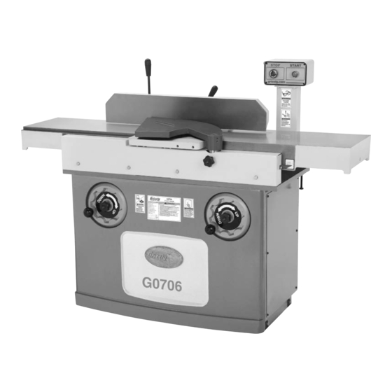
- Page 1 MODEL G0706 12" PARALLELOGRAM JOINTER OWNER'S MANUAL WARNING: NO PORTION OF THIS MANUAL MAY BE REPRODUCED IN ANY SHAPE OR FORM WITHOUT THE WRITTEN APPROVAL OF GRIZZLY INDUSTRIAL, INC.
-
Page 3: Table Of Contents
INTRODUCTION ... 2 SECTION 1: SAFETY ... 6 SECTION 2: CIRCUIT REQUIREMENTS ... 9 SECTION 3: SETUP ... 10 SECTION 4: OPERATIONS ... 19 Table of Contents SECTION 5: ACCESSORIES ... 28 SECTION 6: MAINTENANCE ... 30 SECTION 7: SERVICE ... 31 SECTION 8: WIRING ... -
Page 4: Introduction
INTRODUCTION Manual Accuracy Contact Info your machine may not exactly match the manual Machine Description www.grizzly.com... - Page 5 Identification To reduce the risk of serious injury when using this machine, read and understand this entire manual before beginning any operations.
- Page 6 12" X 60" SHORT BED JOINTER W/ SPIRAL CUTTERHEAD Product Dimensions: Shipping Dimensions: Electrical: Motors: Main Main Specifications: Cutting Capacities MACHINE DATA SHEET MODEL G0706...
- Page 7 Fence Information Cutterhead Information Table Information Construction Table Information Other Information Other Specifications: Features:...
-
Page 8: Section 1: Safety
SECTION 1: SAFETY For Your Own Safety, Read Instruction Manual Before Operating this Machine The purpose of safety symbols is to attract your attention to possible hazardous conditions. This manual uses a series of symbols and signal words intended to convey the level of importance of the safety messages. - Page 9 Safety Instructions for Machinery 7. ONLY ALLOW TRAINED AND PROP- ERLY SUPERVISED PERSONNEL TO OPERATE MACHINERY. 8. KEEP CHILDREN/VISITORS 9. UNATTENDED OPERATION. 10. DO DANGEROUS ENVIRONMENTS. 11. KEEP WORK AREA CLEAN AND WELL LIGHTED. 12. USE A GROUNDED POWER SUPPLY RATED FOR THE MACHINE AMPERAGE.
-
Page 10: Additional Safety For Jointers
Additional Safety for Jointers JOINTER KICKBACK. DO NOT CUTTERHEAD ALIGNMENT. PUSH BLOCKS. WORKPIECE SUPPORT. KICKBACK ZONE. Like all machinery there is potential danger when operating this machine. Accidents are frequently caused by lack of familiarity or failure to pay attention. Use this machine with respect and caution to decrease the risk of operator injury. -
Page 11: Section 2: Circuit Requirements
SECTION 2: CIRCUIT REQUIREMENTS 220V Single-Phase Operation Serious personal injury could occur if you connect the machine to power before com- pleting the setup process. DO NOT connect the machine to the power until instructed later in this manual. Electrocution or fire could result if machine is not correctly grounded or connected to the power... -
Page 12: Section 3: Setup
Wear safety glasses dur- ing the entire setup pro- cess! The Model G0706 is a heavy machine (834 lbs shipping weight). Use power lifting equipment to lift this jointer. Otherwise serious personal injury... - Page 13 Inventory Note: If you can't find an item on this list, check the mounting location on the machine or examine the packaging materials carefully. Occasionally we pre-install certain components for shipping purposes. Crate Contents: (Figure 2 & 3) Figure 2. Figure 3.
-
Page 14: Hardware Recognition Chart
Hardware Recognition Chart... - Page 15 Cleanup Before cleaning, gather the following: H9692—Orange Power Cleaner & Degreaser Figure 5. Note: In a pinch, automotive degreasers, mineral ventative. Before using these products, though, test them on an inconspicuous area of your paint to make sure they will not damage it. Gasoline and petroleum products have low flash points and can explode...
-
Page 16: Site Considerations
Site Considerations Weight Load Machine Data Sheet Space Allocation See below for required space allocation. Children or untrained people may be seriously injured by this machine. Only install in an access restricted location. Physical Environment Electrical Installation Lighting Figure 6. -
Page 17: Moving & Placing
Moving & Placing Base Unit The Model G0706 is a heavy machine. Serious personal injury may occur if safe moving meth- ods are not used. To be safe, get assistance and use power equipment to move the shipping crate and remove the machine from the crate. - Page 18 Assembly To assemble the jointer: Figure 9. Figure 10 Figure 10. Figure 11 Figure 11. Figure 12 Figure 12. Figure 13 Figure 13.
- Page 19 Outfeed Table Height The outfeed table height MUST be set level with the cutting inserts when they are at top-dead-center or the workpiece cannot safely feed across the jointer, which will increase the risk of a kickback injury. Figure 14 Figure 14.
- Page 20 Dust Port DO NOT operate the Model G0706 with- out an adequate dust collection system. This machine creates substantial amounts of wood dust while operating. Failure to use a dust collection system can result in short and long-term respiratory illness.
-
Page 21: Section 4: Operations
OMMEND that you read books, trade maga- zines, or get formal training before begin- ning any projects. Regardless of the con- tent in this section, Grizzly Industrial will not be held liable for accidents caused by lack of training. Operation Overview... -
Page 22: Basic Controls
Basic Controls START Button Figure 16 STOP Button Figure 16. Table Height Figure 17 SERVICE Page 31 Figure 17. Fence Movement Fence Tilting Figure 18. SECTION 7: Figure 18 Figure 18... - Page 23 Stock Inspection & Requirements Follow these rules when choosing and joint- ing stock: contains large or loose knots. Jointing and surface planing with the grain is safer for the operator and pro- duces a better finish. Note: If the grain changes direction along the edge of the workpiece, decrease the depth of cut and make additional passes.
-
Page 24: Squaring Stock
Squaring Stock Squaring stock involves four steps performed in the following order: Surface Plane on the Jointer: Figure 21 Figure 21. Surface Plane on a Thickness Planer: Figure 22 Figure 22. Edge Joint on the Jointer: Figure 23 Figure 23. Rip Cut on a Table Saw: Figure 24 Figure 24. -
Page 25: Surface Planing
Surface Planing 25–26 NOTICE If you are not experienced with a jointer, set the depth of cut to 0" and practice feeding the workpiece across the tables as described for each of the jointing proce- dures. This process will better prepare you for the actual operation. -
Page 26: Edge Jointing
Edge Jointing Figures 27–28 Figure 27. Figure 28. To edge joint on the jointer: Instructions Stock Inspection & Requirement Page 21 Setting Outfeed Table Height Page 33 Note: We suggest ⁄ "– ⁄ " depth of cut for edge jointing, and a more shallow depth for hardwood species or for wide stock. -
Page 27: Bevel Cutting
Bevel Cutting Figures 29–30 Figure 29. Figure 30. To bevel cut on the jointer: Instructions Stock Inspection & Requirement Page 21 Setting Outfeed Table Height Page 33 Note: We suggest ⁄ "– ⁄ " depth of cut for bevel cutting, and a more shallow depth for hardwood species or for wide stock. -
Page 28: Rabbet Cutting
Rabbet Cutting Figures 31-32 NOTICE If you are not experienced with a jointer, set the depth of cut to 0", and practice feeding the workpiece across the tables as described below. This procedure will better prepare you for the actual operation. Figure 31. -
Page 29: Cutterhead Inserts
Cutterhead Inserts Figure 33 Figure 33. Tools Needed To rotate or replace a spiral cutterhead insert: Note: Proper cleaning of the insert, Torx screw, and the cutterhead pocket is critical to achieving a smooth finish. Dirt or dust trapped between the insert and cutterhead will raise the insert slightly and make notice- able marks on your workpiece the next time you cut. -
Page 30: Section 5: Accessories
SECTION 5: ACCESSORIES T21348—Carbide Indexable Insert, 10 Pk. Figure 34. T20501—Face Shield Crown Protector 4" T20502—Face Shield Crown Protector 7" T20503—Face Shield Window T20452—"Kirova" Anti-Reflective S. Glasses T20451—"Kirova" Clear Safety Glasses ® H0736—Shop Fox Safety Glasses H7194—Bifocal Safety Glasses 1.5 H7195—Bifocal Safety Glasses 2.0 H7196—Bifocal Safety Glasses 2.5 T20502... - Page 31 G9256—6" Dial Caliper G9257—8" Dial Caliper G9258—12" Dial Caliper Figure 38. G1029Z2—2HP Dust Collector Figure 39. ® G5562—SLIPIT 1 Qt. Gel G5563—SLIPIT ® 12 oz Spray ® G2871—Boeshield T-9 12 oz Spray G2870—Boeshield ® T-9 4 oz Spray ® H3788—G96 Gun Treatment 12 oz Spray ®...
-
Page 32: Section 6: Maintenance
SECTION 6: MAINTENANCE Always disconnect power to the machine before performing maintenance. Failure to do this may result in serious person- al injury. Schedule Daily Monthly Check Ribbed V-belt Drive Belt Page 42 Cleaning Page 29 Lubrication... -
Page 33: Section 7: Service
SECTION 7: SERVICE Troubleshooting Page 42 Page 42 Page 42 Page 42 Pages 33 & 39 Page 33... - Page 34 Page 33 Page 21 Page 27 Page 27 Page 27 Page 27...
-
Page 35: Checking Outfeed Table Height
Outfeed Table Height Checking Outfeed Table Height Tools Needed To check the outfeed table height: Figure 42 Figure 42. Figure 43 Figure 43. Figure 44 Figure 44. Outfeed Table Height Setting Outfeed Table Height Tools Needed Figure Setting... - Page 36 To set the outfeed table height: Figure 45 Figure 42 Figure 43 8A. (Standard Procedure) Figure 44 8B. (Optional Procedure) Figure 45 Figure 46. Figure 47. Figure 46 Figure 47...
-
Page 37: Checking/Adjusting Table Parallelism
Checking/Adjusting Table Parallelism Tools Needed Checking Outfeed Table Parallelism Figure 48 Figure 49. Figure 50 Figure 45 Figure 50. Checking Infeed Table Figure Table Parallelism Adjusting... - Page 38 Checking Infeed Table Setting Outfeed Table Height Page 33 To check the infeed table: Figure 51. Figure 52 Figure 52. Table Parallelism Adjusting Table Parallelism Figure Important: The steps that follow are intended to be performed directly after the steps involved in "Checking Outfeed Table Parallelism"...
- Page 39 Adjusting Outfeed Table Parallelism Figure 53 Figure 53. Figure 54 Figure 54. Figure 52 Figure 55 Figure 55. Note: The goal of the next step is to bring the outfeed table parallel to the cutterhead body from front-to-back by raising or lowering the front corner of the outfeed table.
-
Page 40: Adjusting Infeed Table Parallelism
Figure 55 Figure 45 Page 34 Note: When adjusted to the correct outfeed table height, use the stop bolt for a conve- nient method of ensuring the outfeed table is set at the proper height. Adjusting Outfeed Parallelism Adjusting Infeed Table Parallelism Adjusting Infeed Table Parallelism Outfeed Table Parallelism... - Page 41 Setting Infeed Table Stop Bolt Figure 57 Figure 57. Page 40 To adjust the infeed table stop bolts: Figure 57 Congratulations! The infeed table stop bolt is now properly set.
-
Page 42: Setting Fence Stops
Calibrating Depth Scale Tools Needed To calibrate the depth scale: Figure 58 Figure 58. Figure 59 Figure 59. Setting Fence Stops Tools Needed To set the 45˚ inward fence stop: Figure 60 Figure 60. Figure 61 Figure 61. Step 2... - Page 43 To set the 90˚ fence stop: Figure 62 Figure 62. To set the 45° outward fence stop: Figure 63. Figure 62 Figure 63 Step 2...
-
Page 44: Drive Belt
Tools needed: To check the belt tension: Figure 64 Figure 64. Figure 65. Note: When properly tensioned, the belt on the Model G0706 should not have more than ⁄ " deflection. Adjusting Belt Tension Tools needed: To adjust the belt tension:... -
Page 45: Pulley Alignment
Figure 66. Checking Belt Tension Replacing Belt Steps 1–3 Adjusting Belt Tension Tension Steps 4–6 Pulley Alignment Figure 66 Page 42 Cutterhead Figure 67. Adjusting Belt Tension Adjusting Belt Figure 68. Checking Belt Tension Figure 67 Motor Figure 68 Page 42... -
Page 46: Section 8: Wiring
SECTION 8: WIRING Wiring Safety Instructions SHOCK HAZARD. MODIFICATIONS. WIRE CONNECTIONS. CIRCUIT REQUIREMENTS. The photos and diagrams included in this section are best viewed in color. You can view these pages in color at www.grizzly.com. WIRE/COMPONENT DAMAGE. MOTOR WIRING. CAPACITORS/INVERTERS. EXPERIENCING DIFFICULTIES. - Page 47 G0706 Electrical Components Figure 69 Figure 70 Figure 71 READ ELECTRICAL SAFETY ON PAGE 44!
- Page 48 G0706 Wiring Diagram MOTOR READ ELECTRICAL SAFETY ON PAGE 44! CONTROL PANEL WARNING! SHOCK HAZARD! Disconnect power before working on wiring. MAGNETIC SWITCH ASSEMBLY 220 VAC L6-20 PLUG (as recommended)
-
Page 49: Section 9: Parts
SECTION 9: PARTS REF PART # DESCRIPTION P0706101 FENCE P0706102 HANDLE ROD P0706103 HANDLE M12-1.75 PN09M HEX NUT M12-1.75 P0706105 CLAMP PCAP64M CAP SCREW M10-1.5 X 25 P0706107 LOCK LEVER ASSY PW06M FLAT WASHER 12MM P0706109 DOUBLE END THREADED ROD PRP03M ROLL PIN 5 X 20 P0706111... - Page 50 Table...
- Page 51 REF PART # DESCRIPTION P0706201 OUTFEED TABLE P0706202 OUTFEED TABLE LIP PCAP84M CAP SCREW M10-1.5 X 35 PLW06M LOCK WASHER 10MM P0706205 DUST BOARD PFH43M FLAT HD SCR M6-1 X 10 P0706207 TABLE SPINDLE P0706208 ROD (SHORT) PSS14M SET SCREW M8-1.25 X 12 P0706210 BED PIVOT PIN PCAP77M...
- Page 52 REF PART # DESCRIPTION P0706301 FRONT CUTTERHEAD SCREW PW01M FLAT WASHER 8MM P0706303 FRONT CUTTERHEAD BUSHING P0706304 FRONT BEARING SUPPORT PB14M HEX BOLT M10-1.5 X 35 PW04M FLAT WASHER 10MM PLW06M LOCK WASHER 10MM P6204Z BALL BEARING 6204Z P0706309 FRONT BEARING COVER PCAP06M CAP SCREW M6-1 X 25 P0706311...
-
Page 53: Stand Assembly
Stand Assembly... -
Page 54: Stand Parts List
REF PART # DESCRIPTION P0706401 HANDWHEEL P0706402 HANDWHEEL DIRECTION LABEL P0706403 HANDWHEEL KNOB PCAP71M CAP SCREW M10-1.5 X 60 PN02M HEX NUT M10-1.5 P0706406 KNOB BOLT P0706407 HANDWHEEL WASHER P0706408 LIFTING FIXING SEAT P0706409 OILER-M6 PCAP31M CAP SCREW M8-1.25 X 25 PLW04M LOCK WASHER 8MM P0706412... - Page 55 MUST maintain the original location and readability of the labels on the machine. If any label is removed or becomes unreadable, REPLACE that label before using the machine again. Contact Grizzly at (800) 523-4777 or www.grizzly.com to order new labels. REF PART #...
-
Page 57: Warranty Card
The following information is given on a voluntary basis. It will be used for marketing purposes to help us develop better products and services. Of course, all information is strictly confidential. Note: We never use names more than 3 times. _____________________________________________________________________ _________________________________________________________________________________ _________________________________________________________________________________... -
Page 59: Warranty And Returns
WARRANTY AND RETURNS... - Page 60 ® Buy Direct and Save with Grizzly – Trusted, Proven and a Great Value! ~Since 1983~ Visit Our Website Today For Current Specials! ORDER 24 HOURS A DAY! 1-800-523-4777...
Need help?
Do you have a question about the G0706 and is the answer not in the manual?
Questions and answers