Table of Contents
Advertisement
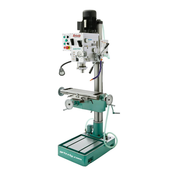
MODEL G0751
HEAVY-DUTY DRILL PRESS
w/AUTOMATIC TAPPING
FUNCTION
OWNER'S MANUAL
(For models manufactured since 1/13)
Copyright © JULy, 2013 By grizzLy indUstriaL, inC.
WARNING: NO PORTION OF THIS MANUAL MAY bE REPRODUCED IN ANY SHAPE
OR FORM WITHOUT THE WRITTEN APPROVAL OF GRIzzLY INDUSTRIAL, INC.
#ts15773 printed in China
Advertisement
Table of Contents

Related Manuals for Grizzly G0751


Summary of Contents for Grizzly G0751
- Page 1 OWNER'S MANUAL (For models manufactured since 1/13) Copyright © JULy, 2013 By grizzLy indUstriaL, inC. WARNING: NO PORTION OF THIS MANUAL MAY bE REPRODUCED IN ANY SHAPE OR FORM WITHOUT THE WRITTEN APPROVAL OF GRIzzLY INDUSTRIAL, INC. #ts15773 printed in China...
- Page 2 This manual provides critical safety instructions on the proper setup, operation, maintenance, and service of this machine/tool. Save this document, refer to it often, and use it to instruct other operators. Failure to read, understand and follow the instructions in this manual may result in fire or serious personal injury—including amputation, electrocution, or death.
-
Page 3: Table Of Contents
Table of Contents INTRODUCTION ..........2 installing/removing tooling ......26 Machine description ........2 installing tooling ..........27 Contact info............ 2 removing tooling ..........27 Manual accuracy ........... 2 spindle speed..........28 identification ........... 3 determining spindle speed ......28 Basic Controls .......... -
Page 4: Introduction
INTRODUCTION Machine Description Manual Accuracy the Model g0751 is a fully-featured drill press that We are proud to provide a high-quality owner’s strikes a great balance between being heavy-duty manual with your new machine! and high-precision. We made every effort to be exact with the instruc-... -
Page 5: Identification
Work Light nozzle r-8 spindle X-axis handwheel X-axis handwheel table y-axis handwheel table z-axis Crank Coolant pump Coolant return hose Base To reduce your risk of serious injury, read this entire manual bEFORE using machine. Model G0751 (Mfg. Since 1/13) -
Page 6: Basic Controls
0.115" of spindle travel. C. Spindle Reverse: starts spindle reverse rotation when in drilling/milling mode. D. Spindle Stop: stops spindle rotation. E. Emergency Stop: Cuts power to the spindle motor and coolant pump. Model G0751 (Mfg. Since 1/13) - Page 7 To prevent damage to the gears, ONLY use the auto-downfeed ON/OFF and rate selec- tor knobs when the spindle is completely stopped. Model G0751 (Mfg. Since 1/13)
-
Page 8: Machine Data Sheet
MACHINE DATA SHEET Customer Service #: (570) 546-9663 · To Order Call: (800) 523-4777 · Fax #: (800) 438-5901 MODEL G0751 HEAVY DUTY DRILL PRESS Product Dimensions: Weight................................794 lbs. Width (side-to-side) x Depth (front-to-back) x Height............29-1/2 x 36-1/2 x 69-1/4 in. - Page 9 The information contained herein is deemed accurate as of 6/30/2013 and represents our most recent product specifications. Model G0751 PAGE 2 OF 2 Due to our ongoing improvement efforts, this information may not accurately describe items previously purchased. Model G0751 (Mfg. Since 1/13)
-
Page 10: Section 1: Safety
Model G0751 (Mfg. Since 1/13) - Page 11 Contact our debris. Make sure they are properly installed, technical support at (570) 546-9663. undamaged, and working correctly. Model G0751 (Mfg. Since 1/13)
-
Page 12: Additional Safety For Drill Presses
If normal safety pre- respect. Failure to do so could result in cautions are overlooked or ignored, seri- serious personal injury, damage to equip- ous personal injury may occur. ment, or poor work results. -10- Model G0751 (Mfg. Since 1/13) -
Page 13: Section 2: Power Supply
To reduce the risk of these hazards, avoid over- loading the machine during operation and make sure it is connected to a power supply circuit that meets the requirements in the following section. -11- Model G0751 (Mfg. Since 1/13) -
Page 14: Grounding Instructions
If the plug does not fit the available receptacle, or the machine must be reconnected for use on a different type of circuit, the reconnection must be made by a qualified electrician and comply with all local codes and ordinances. -12- Model G0751 (Mfg. Since 1/13) -
Page 15: Section 3: Setup
If you cannot find an item on the inventory list, carefully check around/inside the machine and packaging materials. Often, these items get lost in packaging materials while unpacking or they are pre-installed at the factory. -13- Model G0751 (Mfg. Since 1/13) -
Page 16: Cleanup
Figure 5. t23692 orange power degreaser. off the rest with the rag. repeat Steps 2–3 as necessary until clean, then coat all unpainted surfaces with a quality metal protectant to prevent rust. -14- Model G0751 (Mfg. Since 1/13) -
Page 17: Site Considerations
Only install in an Shadows, glare, or strobe effects that may distract access restricted location. or impede the operator must be eliminated. 54" 48" Figure 6. Minimum working clearances. -15- Model G0751 (Mfg. Since 1/13) -
Page 18: Lifting & Placing
Lower table to lowest point (refer to Table remove pallet, then lower machine in place. Movement beginning on Page 23 for detailed instructions). Note: Steps 3 and 5 lower machine center of gravity to increase stability when lifting. -16- Model G0751 (Mfg. Since 1/13) -
Page 19: Anchoring To Floor
MUst follow the anchoring methodology specified by the code. Lag Screw Flat Washer Machine Base Lag Shield Anchor Concrete Drilled Hole Figure 8. popular method for anchoring machinery to a concrete floor. -17- Model G0751 (Mfg. Since 1/13) -
Page 20: Joining Drill Chuck & Arbor
Figure 10. Figure 10. tapping drill chuck/arbor on block of wood. attempt to separate drill chuck and arbor by hand —if they separate, repeat Steps 3–4. -18- Model G0751 (Mfg. Since 1/13) -
Page 21: Test Run
Before beginning any ing power cord plug into matching recep- regular operations, perform the Spindle break-In tacle—the power lamp should light after con- procedure on the next page. nection. -19- Model G0751 (Mfg. Since 1/13) -
Page 22: Spindle Break-In
(refer to Page 32 in the Lubrication subsection for detailed instructions). the spindle break-in is now complete! -20- Model G0751 (Mfg. Since 1/13) -
Page 23: Section 4: Operations
Read books/magazines or get formal training before beginning any proj- ects. Regardless of the content in this sec- tion, Grizzly Industrial will not be held liable for accidents caused by lack of training. -21- Model G0751 (Mfg. Since 1/13) -
Page 24: Headstock Movement
Lock the headstock in place by retightening the operation to avoid unexpected headstock move- locking hex nuts before beginning operation to ment. avoid unexpected headstock movement. -22- Model G0751 (Mfg. Since 1/13) -
Page 25: Table Movement
E. Graduated Dial: displays table travel in increments of 0.001". one full revolution equals 0.100" of travel. the thumb screw can be used to adjust the dial to "0" for relative table position. -23- Model G0751 (Mfg. Since 1/13) -
Page 26: Downfeed
Downfeed Coarse Downfeed Use the coarse downfeed handles to control spindle travel in rapid, large amounts for milling/ drilling. the Model g0751 features four ways to control spindle downfeed: To use coarse downfeed: • Coarse downfeed Make sure spindle is completely stopped. -
Page 27: Auto-Downfeed
-25- Model G0751 (Mfg. Since 1/13) -
Page 28: Depth Digital Display
Tooling the depth digital display on the headstock dis- plays the relative spindle depth. the Model g0751 includes the following spindle tools (see Figure 20): Use Figure 19 and the following descriptions to gain an understanding of the display controls. -
Page 29: Installing Tooling
Working from the top, hand-thread drawbar into tooling until snug, then use a 19mm wrench to tighten it. Note: overtighten drawbar. Overtightening makes tooling removal dif- ficult and could damage arbor and drawbar threads. re-install drawbar cap. -27- Model G0751 (Mfg. Since 1/13) -
Page 30: Spindle Speed
-28- Model G0751 (Mfg. Since 1/13) -
Page 31: Section 5: Accessories
To reduce this risk, only install accessories well as reduce chatter or slip. Buy in bulk and recommended for this machine by Grizzly. save with 5-gallon quantities. NOTICE t23962... - Page 32 " in increments ⁄ ", letter bits from a–z, and 60 number bits. housed in rugged steel case. Figure 29. g9612 test indicator. Figure 32. g3658 titanium drill Bits. www.grizzly.com 1-800-523-4777 order online at or call -30- Model G0751 (Mfg. Since 1/13)
-
Page 33: Section 6: Maintenance
• Check/replace damaged tooling. regular applications of iso 68 way oil (see • Check/repair worn or damaged wires. Page 29 for offerings from grizzly). • Clean debris and built up grime off of machine. • Check/resolve any other unsafe condition. -
Page 34: Headstock Reservoir
MaChine FroM poWer! Clean up any spilled oil to prevent slipping remove the fill plug (see Figure 33). hazards. -32- Model G0751 (Mfg. Since 1/13) -
Page 35: Table Ball Oilers
(see them with mineral spirits and shop rags. Page 29 for offerings from grizzly). We do not recommend using metal needle or lance tips, as Note: The table and saddle each have two oppos- they can push the ball too far into the oiler, break ing ways. -
Page 36: Downfeed Gears
Use the coarse downfeed handles to lower the travel to distribute the lubricant. spindle, then apply a small amount of grease inside the resulting hole. run the spindle up and down several times to distribute the grease. -34- Model G0751 (Mfg. Since 1/13) -
Page 37: Table Leadscrews
Figure 42. y-axis leadscrew location. Use a clean brush to apply a thin coat of oil to the leadscrew threads, then move the table through the X- and y-axis paths to distribute the oil. -35- Model G0751 (Mfg. Since 1/13) -
Page 38: Column Racks
Note: Re-apply oil to the column smooth surfaces not covered by the warranty. that was removed during the cleaning process. -36- Model G0751 (Mfg. Since 1/13) -
Page 39: Checking/Adding Coolant
Tip: Place a couple of magnets inside res- re-install coolant pump before resuming ervoir under return hose to collect metal par- operations. ticles to keep them out of coolant pump. -37- Model G0751 (Mfg. Since 1/13) -
Page 40: Section 7: Service
8. Motor fan is rubbing on fan cover. 8. replace dented fan cover or damaged fan. 9. Motor bearings are at fault. 9. test by rotating shaft; rotational grinding/loose shaft requires bearing replacement. -38- Model G0751 (Mfg. Since 1/13) - Page 41 5. spindle extended too far down. 5. Fully retract spindle and lower headstock. this increases rigidity. Cutting/drilling results not 1. table and spindle are not at 90° to 1. tram the spindle (Page 41). square. each other. -39- Model G0751 (Mfg. Since 1/13)
-
Page 42: Adjusting Gibs
X-axis gib screw (1 of 2) Figure 48. Location of X-axis leadscrew nut for adjusting backlash. y-axis gib screw (1 of 2) Figure 47. table gib screw locations. -40- Model G0751 (Mfg. Since 1/13) -
Page 43: Tramming Spindle
Indicator Holder Spindle Dial Indicator Parallel Block Table Figure 50. dial indicator mounted. -41- Model G0751 (Mfg. Since 1/13) - Page 44 Figure 51, then zero dial. -42- Model G0751 (Mfg. Since 1/13)
-
Page 45: Tightening Return Spring Tension
If the return spring should come loose from the spring cap and rapidly unwind, laceration or impact inju- ries could occur. Always wear heavy leather gloves and safety glasses when adjusting the return spring tension. -43- Model G0751 (Mfg. Since 1/13) -
Page 46: Section 8: Wiring
Technical source. Support at (570) 546-9663. The photos and diagrams included in this section are best viewed in color. You can view these pages in color at www.grizzly.com. -44- Model G0751 (Mfg. Since 1/13) -
Page 47: Electrical Cabinet Wiring
V1 U2 V2 to spindle to Coolant to halogen to power to tapping Motor (Page 47) pump (Page 47) Lamp (Page 47) source (Page 47) Limit switches (Page 47) READ ELECTRICAL SAFETY -45- Model G0751 (Mfg. Since 1/13) ON PAGE 44! - Page 48 Electrical Cabinet transformer Contactor Contactors Fuse timer Figure 53. electrical cabinet wiring. READ ELECTRICAL SAFETY -46- Model G0751 (Mfg. Since 1/13) ON PAGE 44!
-
Page 49: Other Electrical Component Wiring
Cabinet (Page 45) 3 NO 3 NO 1 COM 2 NC Reverse Stop Switch Switch to electrical Grnd Cabinet Halogen (Page 45) Lamp to electrical Cabinet (Page 45) READ ELECTRICAL SAFETY -47- Model G0751 (Mfg. Since 1/13) ON PAGE 44! - Page 50 Other Electrical Components Figure 54. spindle motor wiring. Figure 56. Coolant pump wiring. Figure 55. halogen lamp wiring. Figure 57. tapping limit switch wiring. READ ELECTRICAL SAFETY -48- Model G0751 (Mfg. Since 1/13) ON PAGE 44!
-
Page 51: Section 9: Parts
Please Note: We do our best to stock replacement parts whenever possible, but we cannot guarantee that all parts shown here are available for purchase. Call (800) 523-4777 or visit our online parts store at www.grizzly.com to check for availability. - Page 52 TAPERED PIN 6 X 60 PK65M KEY 4 X 4 X 8 P0751072 LIMIT SWITCH HOUSING PSS22M SET SCREW M4-.7 X 12 PCAP110M CAP SCREW M4-.7 X 6 P0751037 GEAR SHAFT 34T P0751074 LIMIT SWITCH CHNT YBLXW-5/11Q1 -50- Model G0751 (Mfg. Since 1/13)
-
Page 53: Headstock
Headstock 248 249 107-1 107-3 107-4 107-2 107-5 107-7 107-6 107-8 107-9 -51- Model G0751 (Mfg. Since 1/13) -
Page 54: Headstock Parts List
SET SCREW M6-.75 X 8 P6201ZZ BALL BEARING 6201ZZ P0754044 SPINDLE SHAFT PR03M EXT RETAINING RING 12MM P0754045 GEAR 25T P0751221 SPRING RETAINER P0754046 GEAR 18T P0751222 COMPRESSION SPRING P0754047 GEAR 32T P0751223 WORM -52- Model G0751 (Mfg. Since 1/13) - Page 55 KEY 5 X 5 X 30 P0751252 AUTO-DOWNFEED KNOB LABEL P6002ZZ BALL BEARING 6002ZZ P0751253 ELECTRICAL BOX P0751238 FLANGED BEARING SEAT P0751254 ELECTRICAL BOX SIDE COVER PCAP50M CAP SCREW M5 -.8 X 16 P0751255 ELECTRICAL BOX FRONT COVER -53- Model G0751 (Mfg. Since 1/13)
-
Page 56: Base, Table, & Column
Table, & Column 372-1 -54- Model G0751 (Mfg. Since 1/13) - Page 57 CAP SCREW M6-1 X 12 PCAP33M CAP SCREW M5-.8 X 12 P0751375 HALOGEN WORK LIGHT ASSY 24V 35W PCAP45M CAP SCREW M8-1.25 X 45 P0751376 COOLANT PUMP MOUNT PCAP24M CAP SCREW M5-.8 X 16 -55- Model G0751 (Mfg. Since 1/13)
-
Page 58: Electrical Cabinet
P0751404 STOP BUTTON MINGER LA125H-BE102C P0751411 FUSE 2A 250V CERAMIC 5 X 25MM P0751405 COOLANT SWITCH MINGER LA125H-BE102C P0751412 TERMINAL BAR 1P P0751406 E-STOP MINGER LA125H-BE102C P0751413 BACK PLATE P0751407 TRANSFORMER MTE JBK5-63 110-220V -56- Model G0751 (Mfg. Since 1/13) -
Page 59: Accessories
DRILL CHUCK B16 W/CHUCK KEY PAW04M HEX WRENCH 4MM P0754309 SPINDLE SLEEVE MT#3-MT#2 PAW03M HEX WRENCH 3MM P0754310 DRILL CHUCK ARBOR R8-B16 PWR1719 WRENCH 17 X 19 OPEN-ENDS P0754311 SPINDLE SLEEVE R8-MT#3 PWR2224 WRENCH 22 X 24 OPEN-ENDS -57- Model G0751 (Mfg. Since 1/13) -
Page 60: Machine Labels & Cosmetics
Safety labels help reduce the risk of serious injury caused by machine hazards. If any label comes off or becomes unreadable, the owner of this machine MUST replace it in the original location before resuming operations. For replacements, contact (800) 523-4777 or www.grizzly.com. -58-... - Page 61 Would you recommend Grizzly Industrial to a friend? _____ Yes _____No Would you allow us to use your name as a reference for Grizzly customers in your area? Note: We never use names more than 3 times. _____ Yes _____No 10.
- Page 62 FOLD ALONG DOTTED LINE Place Stamp Here GRIZZLY INDUSTRIAL, INC. P.O. BOX 2069 BELLINGHAM, WA 98227-2069 FOLD ALONG DOTTED LINE Send a Grizzly Catalog to a friend: Name_______________________________ Street_______________________________ City______________State______Zip______ TAPE ALONG EDGES--PLEASE DO NOT STAPLE...
-
Page 63: Warranty & Returns
WARRANTY & RETURNS Grizzly Industrial, Inc. warrants every product it sells for a period of 1 year to the original purchaser from the date of purchase. This warranty does not apply to defects due directly or indirectly to misuse, abuse, negligence, accidents, repairs or alterations or lack of maintenance.
Need help?
Do you have a question about the G0751 and is the answer not in the manual?
Questions and answers