Table of Contents
Advertisement
Quick Links
For questions or help with this product contact Tech Support at (570) 546-9663 or techsupport@grizzly.com
We recently discovered the following mistakes in the owner's manual:
•
Incorrect run capacitor listed for vertical spindle motor in parts breakdown.
•
Incorrect markings shown on switches in control panel wiring diagrams.
•
Incorrect wiring diagrams shown for vertical and horizontal spindle motors.
•
Incorrect photos of capacitors and wiring shown of vertical and horizontal spindle motors.
This document provides the relevant updates to the owner's manual that no longer applies—aside from this
information, all other content in the owner's manual applies and MUST be read and understood for your own
safety. IMPORTANT: Keep this update with the owner's manual for future reference.
For questions or help, contact our Tech Support at (570) 546-9663 or techsupport@grizzly.com.
COPYRIGHT © SEPTEMBER, 2014 BY GRIZZLY INDUSTRIAL, INC. REVISED OCTOBER, 2018 (JL)
WARNING: NO PORTION OF THIS MANUAL MAY BE REPRODUCED IN ANY SHAPE
OR FORM WITHOUT THE WRITTEN APPROVAL OF GRIZZLY INDUSTRIAL, INC.
READ THIS FIRST
Revised Capacitor Description
391-1
391-3
391-4
391-2
391-5
REF PART #
DESCRIPTION
391-4 P0757391-4
R CAPACITOR 50M 450V 2 X 4
#MN16770 PRINTED IN CHINA
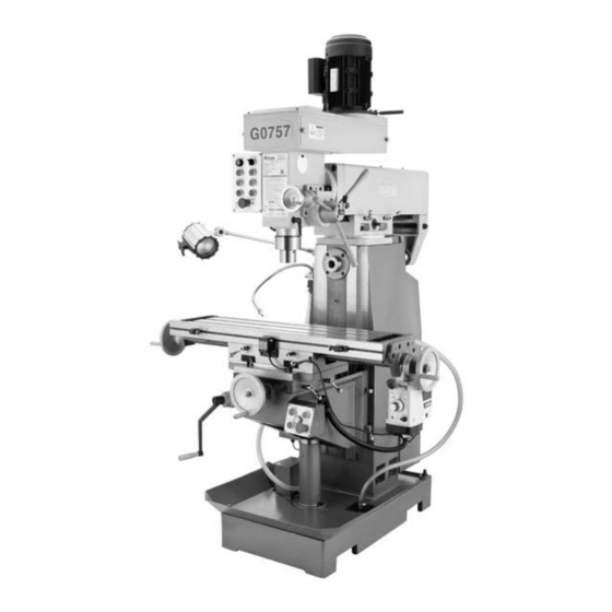
Model G0757
***IMPORTANT UPDATE***
For Machines Mfd. Since 9/13
and Owner's Manual Printed 09/13
391
391-7
391-8
391-6
391-9
Advertisement
Table of Contents

Related Manuals for Grizzly G0757


Summary of Contents for Grizzly G0757
- Page 1 ***IMPORTANT UPDATE*** For Machines Mfd. Since 9/13 and Owner's Manual Printed 09/13 For questions or help with this product contact Tech Support at (570) 546-9663 or techsupport@grizzly.com We recently discovered the following mistakes in the owner's manual: • Incorrect run capacitor listed for vertical spindle motor in parts breakdown.
- Page 2 Replaces Page 57 Control Panel Wiring Diagrams Master Control Panel To Electrical Cabinet (Page 55) Horizontal Control Panel To Electrical Cabinet (Page 55) G0757 Manual Update (Mfd. Since 9/13)
- Page 3 To Master Control Panel (Page 57) Ground Start Capacitor Capacitor 50MFD 300MFD 450VAC 250VAC V1 U2 Horizonal Spindle Motor To Electrical Cabinet (Page 55) Ground Start Capacitor Capacitor 20MFD 150MFD 450VAC 250VAC V1 U2 G0757 Manual Update (Mfd. Since 9/13)
- Page 4 Replaces Page 61 Motor & Other Component Wiring Figure 75. Vertical spindle motor wiring. Figure 77. Coolant pump wiring. Figure 76. Horizontal spindle motor wiring. Figure 78. Horizontal spindle V-belt cover safety switch. G0757 Manual Update (Mfd. Since 9/13)
- Page 5 OWNER'S MANUAL (For models manufactured since 6/13) COPYRIGHT © SEPTEMBER, 2013 BY GRIZZLY INDUSTRIAL, INC. WARNING: NO PORTION OF THIS MANUAL MAY BE REPRODUCED IN ANY SHAPE OR FORM WITHOUT THE WRITTEN APPROVAL OF GRIZZLY INDUSTRIAL, INC. #TS15822 PRINTED IN CHINA...
- Page 6 This manual provides critical safety instructions on the proper setup, operation, maintenance, and service of this machine/tool. Save this document, refer to it often, and use it to instruct other operators. Failure to read, understand and follow the instructions in this manual may result in fire or serious personal injury—including amputation, electrocution, or death.
-
Page 7: Table Of Contents
Table of Contents INTRODUCTION ..........2 Downfeed Controls ........33 Machine Description ........2 Tramming the Mill ........34 Contact Info............ 2 SECTION 5: ACCESSORIES ......36 Manual Accuracy ........... 2 Left Front View Identification ......3 SECTION 6: MAINTENANCE ......40 Right Front View Identification ....... -
Page 8: Introduction
INTRODUCTION Machine Description Manual Accuracy The Model G0757 Milling Machine has a verti- We are proud to provide a high-quality owner’s cal and horizontal spindle that are designed to manual with your new machine! remove material from a metal workpiece secured to the work table or a mill vise. -
Page 9: Left Front View Identification
Motor Master Control Panel Vertical V-Belt Cover Fine Downfeed Horizontal Arbor Handwheel Support Vertical Spindle Halogen Work Light Coolant Nozzle Horizontal V-Belt Cover Y-Axis X-Axis Handwheel Handwheel Z-Axis Electrical Crank Cabinet Splash Coolant Pump Base Model G0757 (Mfg. Since 6/13) -
Page 10: Right Front View Identification
Right Front View Identification Motor Handle Vertical V-Belt Cover Coarse Downfeed Lever Controls Horizontal Spindle X-Axis Handwheel X-Axis Power Feed Coolant Return Hose Horizontal Spindle Control Sub-Panel Model G0757 (Mfg. Since 6/13) -
Page 11: Basic Controls
H. Forward Button (Horizontal Spindle Starts horizontal spindle forward rotation (counterclockwise as viewed from the front of the machine). Coolant Pump Switch: Starts/stops the coolant pump and the flow of coolant. Figure 2. Master control panel. Model G0757 (Mfg. Since 6/13) - Page 12 H. ON/OFF Switch: Enables/disables power to the unit. Rapid Traverse Button: Once the direction- al lever has been activated, causes the table to travel at full speed while pushed. Model G0757 (Mfg. Since 6/13)
-
Page 13: Machine Data Sheet
MACHINE DATA SHEET Customer Service #: (570) 546-9663 · To Order Call: (800) 523-4777 · Fax #: (800) 438-5901 MODEL G0757 9" X 39" HORIZONTAL / VERTICAL MILL WITH POWER FEED Product Dimensions: Weight................................1874 lbs. Width (side-to-side) x Depth (front-to-back) x Height............53-1/2 x 54-7/8 x 81-7/8 in. - Page 14 The information contained herein is deemed accurate as of 3/1/2015 and represents our most recent product specifications. Model G0757 PAGE 2 OF 3 Due to our ongoing improvement efforts, this information may not accurately describe items previously purchased. Model G0757 (Mfg. Since 6/13)
- Page 15 The information contained herein is deemed accurate as of 3/1/2015 and represents our most recent product specifications. Model G0757 PAGE 3 OF 3 Due to our ongoing improvement efforts, this information may not accurately describe items previously purchased. Model G0757 (Mfg. Since 6/13)
-
Page 16: Section 1: Safety
Everyday ery. Never operate under the influence of drugs or eyeglasses are NOT approved safety glasses. alcohol, when tired, or when distracted. -10- Model G0757 (Mfg. Since 6/13) - Page 17 Contact our debris. Make sure they are properly installed, Technical Support at (570) 546-9663. undamaged, and working correctly. -11- Model G0757 (Mfg. Since 6/13)
-
Page 18: Additional Safety For Milling Machines
If normal safety respect. Failure to do so could result in precautions are overlooked or ignored, serious personal injury, damage to equip- serious personal injury may occur. ment, or poor work results. -12- Model G0757 (Mfg. Since 6/13) -
Page 19: Section 2: Power Supply
To reduce the risk of these hazards, avoid over- loading the machine during operation and make sure it is connected to a power supply circuit that meets the requirements in the following section. -13- Model G0757 (Mfg. Since 6/13) -
Page 20: Grounding Instructions
Minimum Gauge Size ......12 AWG of circuit, the reconnection must be made Maximum Length (Shorter is Better)..50 ft. by a qualified electrician and comply with all local codes and ordinances. -14- Model G0757 (Mfg. Since 6/13) -
Page 21: Section 3: Setup
• We recommend a qualified electrician to materials shipped with this ensure a safe and code-compliant connec- machine. Discard immediately. tion to the power source (refer to Page 13 for details). -15- Model G0757 (Mfg. Since 6/13) -
Page 22: Inventory
⁄ –20 x 13 ⁄ " ..........1 packaging materials. Often, these items get lost in packaging materials while unpack- ing or they are pre-installed at the factory. -16- Model G0757 (Mfg. Since 6/13) -
Page 23: Cleanup
Figure 7. T23692 Orange Power Degreaser. off the rest with the rag. Repeat Steps 2–3 as necessary until clean, then coat all unpainted surfaces with a quality metal protectant to prevent rust. -17- Model G0757 (Mfg. Since 6/13) -
Page 24: Site Considerations
Only install in an Shadows, glare, or strobe effects that may distract access restricted location. or impede the operator must be eliminated. Wall 30" Minimum Clearance 30" ⁄ " Minimum Clearance 56" Figure 8. Minimum working clearances. -18- Model G0757 (Mfg. Since 6/13) -
Page 25: Lifting & Placing
Make sure to retighten lock levers and bolts before lifting mill again. — If mill lifts evenly, remove shipping pallet and lower mill. Figure 9. Using lifting straps to lift and move mill. -19- Model G0757 (Mfg. Since 6/13) -
Page 26: Leveling
Figure 11. Example of a precision level (Model H2683 shown). Lag Screw Flat Washer Machine Base Lag Shield Anchor Concrete Drilled Hole Figure 12. Popular method for anchoring machinery to a concrete floor. -20- Model G0757 (Mfg. Since 6/13) -
Page 27: Test Run
Clear away all tools and objects used during power source before investigating or cor- assembly and preparation. recting potential problems. Make sure mill is properly lubricated (refer to Lubrication section beginning on Page 41 for specific details). -21- Model G0757 (Mfg. Since 6/13) -
Page 28: Power Feed Test Run
OFF. Congratulations! The Test Run of the mill is complete. Continue to the next page to per- form the Spindle Break-In and Inspections & Adjustments procedures. -22- Model G0757 (Mfg. Since 6/13) -
Page 29: Spindle Break-In
Repeat Steps 2–4 with horizontal spindle. Check tension of all V-belts, and retension if necessary (refer to V-Belt Service on Page 50 for detailed instructions). The spindle break-in is now complete! -23- Model G0757 (Mfg. Since 6/13) -
Page 30: Section 4: Operations
Read books/magazines or get formal training before beginning any proj- ects. Regardless of the content in this sec- tion, Grizzly Industrial will not be held liable for accidents caused by lack of training. -24- Model G0757 (Mfg. Since 6/13) -
Page 31: Graduated Index Rings
0.200" of travel. Additionally, each dial has a thumbscrew that is used to adjust the dial to zero. Graduated Rings Figure 15. Locations of graduated rings. -25- Model G0757 (Mfg. Since 6/13) -
Page 32: Head Tilt
When tilting the head back to 90°, you will need to tram it to ensure the spindle is perpendicular to the table. Refer to the Tramming the Mill section on Page 34 for detailed instructions. -26- Model G0757 (Mfg. Since 6/13) -
Page 33: Ram Movement
Figure 19. Ram back-and-forth controls. Rotate pinion gear bolt to move ram until spindle is in desired position. Retighten lock handles to secure ram move- ment vbefore resuming operation before resuming operation. -27- Model G0757 (Mfg. Since 6/13) -
Page 34: Loading/Unloading Tooling
Support tooling with one hand, then com- pletely unthread drawbar from tooling. -28- Model G0757 (Mfg. Since 6/13) -
Page 35: Converting To Horizontal Setup
Align keyway of arbor with protruding pin inside spindle taper, then firmly push arbor The Model G0757 includes two horizontal arbors into spindle to seat it (see Figure 23). with spacers that accommodate tooling with 1"... - Page 36 Re-install arbor support and properly position and secure ram for the next operation. Figure 24. Horizontal arbor and cutter installed. 11. Secure arbor support by retightening support locking bolt. 12. Secure arbor assembly with the right-hand arbor nut. -30- Model G0757 (Mfg. Since 6/13)
-
Page 37: Spindle Speed
Also, there are a large number of easy-to-use spindle speed calculators that can be found on the internet. These sources will help you take into account all applicable variables to determine the best spindle speed for the operation. -31- Model G0757 (Mfg. Since 6/13) -
Page 38: Setting Horizontal Spindle Speed
V-belt tension. Figure 28. Checking V-belt tension. Note: You may have to bump the lower idler pulley with the deadblow hammer to get it to Re-install V-belt covers before connecting move. machine to power. -32- Model G0757 (Mfg. Since 6/13) -
Page 39: Downfeed Controls
Retighten hex nut behind lower idler pulley bracket. Coarse Downfeed Levers: Manually control rapid downfeed travel. Close and latch V-belt cover. Quill Lock: Secures the quill in place for increased stability during operations. -33- Model G0757 (Mfg. Since 6/13) -
Page 40: Tramming The Mill
Depending on your operation, you may choose to tram the spindle to the top surface of the workpiece after it is mounted instead of tram- ming to the table. -34- Model G0757 (Mfg. Since 6/13) - Page 41 Retighten the tilting hex nuts. Table (Top View) Parallel Block Indicator Spindle Figure 34. Setup for the X-axis adjustment. -35- Model G0757 (Mfg. Since 6/13)
-
Page 42: Section 5: Accessories
To reduce this risk, only install accessories well as reduce chatter or slip. Buy in bulk and recommended for this machine by Grizzly. save with 5-gallon quantities. NOTICE T23962... - Page 43 Model H9599 has 320 pages. Model easy to read 0°–360° scales. G5053 has 275 pages. Figure 41. G7154 Precision Milling Vise. H9599 G5053 Figure 39. Great texts for mill/drills. www.grizzly.com 1-800-523-4777 order online at or call -37- Model G0757 (Mfg. Since 6/13)
- Page 44 Figure 42. T10442 10-Pc. Milling Tool Kit. G7066—5" Tilting/Swiveling Milling Vise H7576—Precision Self-Centering Vise G7066 Figure 45. G1076 52-PC. Clamping Kit. H7576 Figure 43. Specialty milling vises. www.grizzly.com 1-800-523-4777 order online at or call -38- Model G0757 (Mfg. Since 6/13)
- Page 45 Housed in rugged steel case. dial face. Figure 51. G3658 Titanium Drill Bits. Figure 48. G9612 Test Indicator. www.grizzly.com 1-800-523-4777 order online at or call -39- Model G0757 (Mfg. Since 6/13)
-
Page 46: Section 6: Maintenance
Worn, frayed, cracked, or damaged wires. • Emergency STOP button not working cor- rectly. Worn or loose V-belts (see Page 50). • • Missing or open belt guards/door. • Coolant not flowing correctly. • Any other unsafe condition. -40- Model G0757 (Mfg. Since 6/13) -
Page 47: Cleaning & Protecting
Typically, a thin Quill Rack & Pinion film of way oil is all that is necessary for protection Table Leadscrews (refer to Page 36 for way oil from Grizzly). Ram Ways Z-Axis Bevel Gears X-Axis Power Feed Gears The recommended lubrication schedule is based on light-to-medium usage. -
Page 48: Ball Oilers
Proper lubrication of ball oilers is done with a pump-type oil can that has a plastic or rubberized cone tip (see Page 36 for offerings from Grizzly). We do not recommend using metal needle or lance tips, as they can push the ball too far into the oiler, break the spring seat, and lodge the ball in the oil galley. -
Page 49: Vertical Spindle Bearings
When dry, use a brush to apply a thin coat of grease to the teeth, then move the quill up and down several times to evenly distribute the grease. -43- Model G0757 (Mfg. Since 6/13) -
Page 50: Ram Ways
Figure 62. Location of Z-axis bevel gears. When dry, use a brush to apply a thin coat of grease to the teeth, then move the table up and down to evenly distribute the grease. -44- Model G0757 (Mfg. Since 6/13) -
Page 51: X-Axis Power Feed Gears
Remove the brass bevel gear from the repeat Steps 2–8 until it is. leadscrew, then remove the leadscrew align- ment key (see Figure 63). Drive Brass Gear Bevel Gear Figure 63. Power feed gears and key. -45- Model G0757 (Mfg. Since 6/13) -
Page 52: Coolant
Running the coolant pump without ade- quate coolant in the reservoir may perma- nently damage the coolant pump, which will not covered by the warranty. -46- Model G0757 (Mfg. Since 6/13) -
Page 53: Changing Coolant
Tip: Place a couple of magnets inside the reservoir under the return screen to collect metal particles and keep them out of the cool- ant pump. Re-install the return screen before resuming milling operations. -47- Model G0757 (Mfg. Since 6/13) -
Page 54: Section 7: Service
7. Motor fan is rubbing on fan cover. 7. Replace dented fan cover or damaged fan. 8. Motor bearings are at fault. 8. Test by rotating shaft; rotational grinding/loose shaft requires bearing replacement. -48- Model G0757 (Mfg. Since 6/13) - Page 55 5. Spindle extended too far down. 5. Fully retract spindle and raise table. This increases rigidity. Cutting results not square. 1. Table and spindle are not at 90° to 1. Tram the spindle (Page 34). each other. -49- Model G0757 (Mfg. Since 6/13)
-
Page 56: V-Belt Service
V-belts and pulleys (see Figure 65). Center Pulley Hex Nut Motor Mount Hex Bolt (1 of 2) Motor Handle Figure 65. Vertical spindle V-belt covers removed to gain access to vertical spindle V-belts and pulleys. -50- Model G0757 (Mfg. Since 6/13) -
Page 57: Tensioning Lower Horizontal Spindle V-Belts
Note: There is proper V-belt tension when Retighten the hex nut and secure the V-belt approximately ⁄ " – ⁄ " deflection is achieved cover. (see Figure 66 on the previous page) by applying moderate pressure midway between the pulleys. -51- Model G0757 (Mfg. Since 6/13) -
Page 58: Adjusting Gibs
Note: Remove the way cover behind the table to gain access to the rear Y-axis gib adjustment screw. X-Axis Gib Screw (1 of 2) Y-Axis Gib Screw (1 of 2) Figure 69. Locations of X- and Y-axis gib adjustment screws. -52- Model G0757 (Mfg. Since 6/13) -
Page 59: Adjusting Leadscrew Backlash
Figure 71. Location of X-axis leadscrew nut cap a long 4mm hex wrench to tighten/loosen the cap screws for adjusting backlash. screws on the leadscrew nut. This adjusts the force the leadscrew nut exerts on the leadscrew threads. -53- Model G0757 (Mfg. Since 6/13) -
Page 60: Section 8: Wiring
Technical source. Support at (570) 546-9663. The photos and diagrams included in this section are best viewed in color. You can view these pages in color at www.grizzly.com. -54- Model G0757 (Mfg. Since 6/13) -
Page 61: Electrical Cabinet Wiring Diagram
To Horizontal Supply Spindle Spindle Control To Work V-Belt Cover (Page 60) Motor Sub-Panel To Table Lamp Limit Switch (Page 59) (Page 57) Power Feed (Page 60) (Page 60) READ ELECTRICAL SAFETY -55- Model G0757 (Mfg. Since 6/13) ON PAGE 54! - Page 62 Electrical Cabinet Wiring Figure 72. Electrical cabinet wiring. READ ELECTRICAL SAFETY -56- Model G0757 (Mfg. Since 6/13) ON PAGE 54!
-
Page 63: Control Panel Wiring Diagrams
Control Panel Wiring Diagrams Master Control Panel To Electrical Cabinet (Page 55) Horizontal Control Panel To Electrical Cabinet (Page 55) READ ELECTRICAL SAFETY -57- Model G0757 (Mfg. Since 6/13) ON PAGE 54! - Page 64 Control Panel Wiring Figure 73. Master control panel wiring. Figure 74. Horizontal spindle control sub-panel. READ ELECTRICAL SAFETY -58- Model G0757 (Mfg. Since 6/13) ON PAGE 54!
-
Page 65: Motor Wiring Diagrams
Capacitor 200MFD 300MFD 250VAC 250VAC Ground To Master Control Panel (Page 57) Horizontal Spindle Motor Start Capacitor Capacitor 20MFD 150MFD 450VAC 250VAC Ground To Electrical Cabinet (Page 55) READ ELECTRICAL SAFETY -59- Model G0757 (Mfg. Since 6/13) ON PAGE 54! -
Page 66: Other Component Wiring Diagrams
Limit Switch Chint YBLXW-W11Q1 To Electrical Cabinet (Page 55) Ground To Electrical Cabinet (Page 55) Halogen 220VAC Work Lamp Nema 6-20 Plug (As Recommended) To Electrical Cabinet (Page 55) READ ELECTRICAL SAFETY -60- Model G0757 (Mfg. Since 6/13) ON PAGE 54! - Page 67 Motor & Other Component Wiring Figure 75. Vertical spindle motor wiring. Figure 77. Coolant pump wiring. Figure 76. Horizontal spindle motor wiring. Figure 78. Horizontal spindle V-belt cover safety switch. READ ELECTRICAL SAFETY -61- Model G0757 (Mfg. Since 6/13) ON PAGE 54!
-
Page 68: Section 9: Parts
Please Note: We do our best to stock replacement parts whenever possible, but we cannot guarantee that all parts shown here are available for purchase. Call (800) 523-4777 or visit our online parts store at www.grizzly.com to check for availability. - Page 69 P0757090 COOLANT NOZZLE ASSEMBLY P0757044 SLEEVE P0757091 COOLANT HOSE 1/2" X 36" P0757045 CAP SCREW M6-1 X 18 P0757092 COOLANT HOSE CLAMP 3/4" P0757046 Z-AXIS GIB P0757093 LIMIT SWITCH CHINT XBLXW-W11Q1 P0757047 BALL OILER 8MM TAP-IN -63- Model G0757 (Mfg. Since 6/13)
-
Page 70: Table
Table -64- Model G0757 (Mfg. Since 6/13) - Page 71 P0757152 DOWEL PIN 6 X 25 P0757125 X-AXIS GIB P0757153 COOLANT HOSE CONNECTOR 1/2" NPT P0757126 GIB SCREW M8-1.25 P0757154 COOLANT HOSE CLAMP 3/4" P0757127 SADDLE P0757155 COOLANT HOSE 1/2" X 36" P0757128 Y-AXIS GIB -65- Model G0757 (Mfg. Since 6/13)
-
Page 72: Horizontal Spindle & Motor
Horizontal Spindle & Motor 211 212 250-1 250-3 250-2 250-4 250-8 250-5 250-9 250-6 250-7 -66- Model G0757 (Mfg. Since 6/13) - Page 73 HORIZONTAL ARBOR NUT 1-8 P0757236 HEX NUT M16-2 P0757265 ARBOR SPACER 1" X 1" P0757237 FLAT WASHER 16MM P0757266 ARBOR SPACER 1" X 2" P0757238 TENSION ROD END M8-1.25 X 90 P0757267 ARBOR SPACER 1" X 3-1/8" -67- Model G0757 (Mfg. Since 6/13)
-
Page 74: Headstock
Headstock 391-1 391-8 391-7 391-3 391-2 391-6 391-4 391-9 391-5 315 316 349 350 327 328 329 331 332 -68- Model G0757 (Mfg. Since 6/13) - Page 75 ADJUSTABLE HANDLE M10-1.5 X 90 P0757396 CAP SCREW M8-1.25 X 25 P0757351 SET SCREW M10-1.5 X 10 P0757397 V-BELT A29 P0757352 SET SCREW M10-1.5 X 10 P0757398 V-BELT A29 P0757353 COVER PLATE P0757399 VERTICAL DRAWBAR 7/16-20 X 20 -69- Model G0757 (Mfg. Since 6/13)
-
Page 76: Electrical Components
P0757418 HORIZONTAL CONTROL PANEL PLATE P0757408 TERMINAL BAR 1P P0757419 HORIZONTAL CONTROL PANEL BOX P0757409 ELECTRICAL BACK PLATE P0757420 GROUNDING BLOCK P0757410 ELECTRICAL CABINET W/DOOR P0757421 RELAY OMRON MY4N-J P0757411 MASTER CONTROL PANEL PLATE -70- Model G0757 (Mfg. Since 6/13) -
Page 77: Accessories
P0757506 SPINDLE SLEEVE R8-MT#3 P0757515 FLAT WASHER 14MM P0757507 WRENCH 17 X 19MM OPEN-ENDS P0757516 HEX NUT M14-2 P0757508 WRENCH 22 X 24MM OPEN-ENDS P0757517 DRILL CHUCK B16 W/CHUCK KEY P0757509 HEX WRENCH 8MM -71- Model G0757 (Mfg. Since 6/13) -
Page 78: Right Side Machine Labels
Safety labels help reduce the risk of serious injury caused by machine hazards. If any label comes off or becomes unreadable, the owner of this machine MUST replace it in the original location before resuming operations. For replacements, contact (800) 523-4777 or www.grizzly.com. -72-... -
Page 79: Left Side Machine Labels
Left Side Machine Labels REF PART # DESCRIPTION REF PART # DESCRIPTION P0757603 DISCONNECT WARNING LABEL P0757612 BIOHAZARD WARNING LABEL P0757606 GRIZZLY PUTTY TOUCH-UP PAINT -73- Model G0757 (Mfg. Since 6/13) - Page 80 -74- Model G0757 (Mfg. Since 6/13)
- Page 81 Would you recommend Grizzly Industrial to a friend? _____ Yes _____No Would you allow us to use your name as a reference for Grizzly customers in your area? Note: We never use names more than 3 times. _____ Yes _____No 10.
- Page 82 FOLD ALONG DOTTED LINE Place Stamp Here GRIZZLY INDUSTRIAL, INC. P.O. BOX 2069 BELLINGHAM, WA 98227-2069 FOLD ALONG DOTTED LINE Send a Grizzly Catalog to a friend: Name_______________________________ Street_______________________________ City______________State______Zip______ TAPE ALONG EDGES--PLEASE DO NOT STAPLE...
-
Page 83: Warranty & Returns
WARRANTY & RETURNS Grizzly Industrial, Inc. warrants every product it sells for a period of 1 year to the original purchaser from the date of purchase. This warranty does not apply to defects due directly or indirectly to misuse, abuse, negligence, accidents, repairs or alterations or lack of maintenance.
Need help?
Do you have a question about the G0757 and is the answer not in the manual?
Questions and answers