Table of Contents
Advertisement
perator's
I:RnFrSMRN°
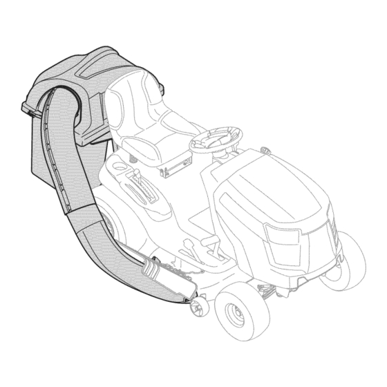
TWO BiN BAGGER
Model No. 247.240193
• Espanol,
p. 18
iMPORTANT:
Read and follow
all Safety
Rules and instructions
before
operating
this equipment.
For answers
to your questions
about
this product,
call:
1-800=659=5917
Craftsman Tractor Help Line
7 am = 7 pm CT, Mort. =Sun.
Sears Brands
Management
Corporation,
Hoffman
Estates,
IL 60179 U.S.A.
Visit
our website:
www.craftsman.com
FormNo.769-08766
(February 1,2013)
Advertisement
Table of Contents

Related Manuals for Craftsman 247.240193


Summary of Contents for Craftsman 247.240193
- Page 1 Read and follow all Safety 1-800=659=5917 Rules and instructions before operating this equipment. Craftsman Tractor Help Line 7 am = 7 pm CT, Mort. =Sun. Sears Brands Management Corporation, Hoffman Estates, IL 60179 U.S.A. Visit our website: www.craftsman.com...
- Page 2 FOR ONE YEAR fromthe dateof purchase, this product i s warrantedagainst a nydefects in material o r workmanship. Adefective productwill bereplaced freeof charge. Forwarrantycoverage d etailsto obtainfreereplacement, visit thewebsite:www.craftsman.com Thiswarrantyis voidif thisproductiseverusedwhileprovidingcommercial services o r if rentedto anotherperson. Thiswarrantygivesyouspecific legalrights,andyoumayalsohaveotherrightswhichvaryfrom stateto state.
- Page 3 This symbol points out i mportant s afety instructions w hich,if not Thismachinewasbuilt to beoperatedaccording t o the safeoperation followed, could endangerthe personalsafetyand/orproperty of practicesin this manual.Aswith anytype of powerequipment, yourself a ndothers. Read andfollow all instructions i n this manual carelessness o r error on the part of the operatorcanresultin seriousinjury.
- Page 4 Keep all m ovement on the slopes slow a nd g radual. Do not make sudden GENERAL SERVICE changes inspeed or direction. Rapid engagement or braking could cause Before cleaning, r epairing, or inspecting, makecertainthe blade(s) a ndall the front of t he machine toliftand r apidly flip over backwards which could...
- Page 5 10° Slope 10° Slope (OK) (TOO STEEP) Figure 1 Figure2 10odashedline USETHiSSLOPE GAUGE TO DETERMINE iF A SLOPE iS TOOSTEEP FORSAFEOPERATION! Tocheckthe slope, proceedas follows: 1. Removethis pageandfold along the dashedline. 2. Locatea vertical object on or behindthe slope(e.g. a pole,building,fence, tree, etc.) 3.
- Page 6 Beforebeginning installation, r emove all partsfromthe cartonto makesureeverything is present. C arton contents arelistedandshownbelow.Twohardwarepacks are includedinthiskit andaredetailedon the followingpage. Hitch Bracket Kit(3brackets) Self-Adhesive Foam Strip Upper C hute S upport Mounting B racket Kit(2 hardware) brackets & Hinge Cover Pin Hitch Support Upright S upport Discharge Chute Elbow...
- Page 7 Estekit dec#sped sesuministracondosnumeros de referendas d eclientesencerrados. 5erecomienda c onsuitarlosnumeros dereferencia de losclientes contralas siguientes ilustraciones. Las cantidades decadaartkulo seindica entrepar#ntesis, mientras queel ntimero aparece juntoacadaitem. Hardware Pack for 689-00312 Hardware Pack 689-00313 723-04008/__. 711-05063 © 710-0276 711-0309A 736-0204 912-3027 720-04122 936-0176 714-0117...
- Page 8 Assembling the Mounting Hardware Assemble MountingBrackets Toassemble the bagger m ountingassembly, locatethe hitchbracketkit andfollow If notalready installed b ythefactory,install a shoulder b oltfrom your thesesteps: hardware pack ontoeachbracket, s ecuring t hemwith flangelocknutsalso Attach thetwohitchside brackets t othe universal rearattachment bracket using included inthe hardware pack included withthesebrackets.
- Page 9 Installthe uprightsupportbracket o ntothe mountingassembly onthe MountAssembly on Tractor tractorbyhookingit overthe cross mountingbracketandaligningit with Installthe mountingassembly o n the tractorasfollows: the mountingholeindicating the decksizeyourmachine isequipped with, asshownin Figure 7. Place the hooked endsofthe bagger m ounting assembly o verthe shoulder boltsonthe mountingbrackets p reviously installed o nthetractorin Figure 1.
- Page 10 Installthe hanger a ssembly o ntothe uprightsupportbracket u singa Installthe grass catchercoverontothe bagsupportassembly, asseenin carriage bolt (710-0276) andwingknob(720-04122) from hardware pack Figure 11.Thegrass catcher c overgoesinside of the two mountingtabson 689-00312. SeeFigure 9. the bagsupportassembly. Figure 11 Slide the hingepin intothe hole located onthe mountingtab,asin Figure Assembling RemainingBaggerComponents 12.
- Page 11 "_ Installbothgrassbagsontothe bagsupportassembly byinsertingthe front edgein first (1),asseeninFigure15,andsettingthe back edgedown(2) until it fits into the assembly. Figure 13 Flipseatforward. OpenHoodbypushing in onthe rear,right-side tab with yourrighthand,as Figure 15 seenin1ofFigure 14,andlifting thecover w ith yourleft hand inthe centerrear ofthe bagger c over, 2 . Figure 14...
- Page 12 Installingthe DeckChute OnTractorswith Older DeckConfigurations Note: Determine if yourdeckisa newermodel, o r an oldermodel.Refer t o Installthe rubberchutestrap,from hardwarepack 689-00313, ontothe the upperinsetof Figure17.Ifyourdeckhas a mountingstudpresent, t hen chuteelbow usingtheclevis pin(711-0S063), washer ( 736-0204) andBow-tie youhaveanewerdeckmodelandyouwouldfollowthe instructions below. cotterpin(714-04040) fromhardware p ack 689-00313. See Figure 18.Secure t he If nostud ispresent, r eferto the instructions titled OnTractors With Older endofthestrap utilizing the hole furthest f romtheend, i nsert t he torsion spring hook (732-04510A) intotheotherend.
- Page 13 Installingthe UpperChuteTube Peel t he backingoff of the self-adhesive f oamstrip (721-04388) that has beenincluded withinyourContents of Carton. A pplyit to the upperchute, flushagainstthe flangeasshowninFigure 22. Figure 20 Note: Ondecks withoutdeckwheels,hookthe retainerstrapintothe hole provided inthe flangeonthe front-sideof the cuttingdeck.SeeFigure 21. Figure 22 With the grass catchercoveropen,install the upperdischarge c hutethrough the discharge chuteopening, a sseenin Figure 23.
- Page 14 Withthe ability nowto wigglethe discharge chutetubeback andforth,slide it overthechuteelbow mounted on the cuttingdeck,asshownin Figure 24. Figure 24 Continue to workthe discharge chutedown overthe chuteelbowuntil the grooveonthe discharge c hutealignswith the upperchutesupport,asseen inthe insetof Figure 25. Figure25 Close thegrasscatcher c over.
- Page 15 Empty the grass clippingsat aproperdisposal s ite.Grasp the handleat the BaggerOperation bottomof the bagwith onehand,andwiththe otherhandsteadythe bag, NOTE: Whenbothgrass bagsarefull, place the tractoronafirm, levelsurface, andemptythe contents. disengage t he PTO (BladeEngage), turnthe tractorengineoffandsetthe parking Replace g rassbags, c loselid,flip downseat,restartyourtractorandresume brake.
- Page 16 19 j...
- Page 17 CRAFTSMAN TWOBINBAGGER Model No.247.240193 To purchase replacement parts, call1-800-469-4663 Ref, I Part Number Description 689-00304 Mounting Bracket Kit (Incl. ref. 16, 17, 18) 710-0276 Carriage Screw, 5/16-18 x 1.00" 711-0309A Clevis Pin, .62" Dia. 711-05049 Attachment Pin, 1/4 x 0.66 Lg.
- Page 18 DURANTEun aSodesde la fecha de compra,este productoestAgarantizado contracualquierdefectode materialo manode obra.Un producto defectuososer_reemplazado sin cargo. Paraque detallesde la coberturade garantiaobtenerun reemplazo libre,visiteel sitio web: www.craftsman.com EstagarantiaserAnula si este productose utilizamientrasque proporcionaservicioscomercialeso Si alquilaa otra persona. Estagarantiale otorgaderechoslegalesespecificos,y ustedtambi_npuedetenerotros derechosque variande estadoa estado.
- Page 19 Esta rn&quina rue construidapara seroperadade acuerdocon La presenciade este sirnboloindicaque setrata de instrucciones las reglasde seguridadcontenidasen este manual.AI igualque irnportantesde seguridadque se deben respetarpara evitar concualquiertipo de equipo rnotorizado, u n descuidoo error por poner en peligrosu seguridadpersonaly/o materialy la de otras partedel operadorpuedeproducirlesionesgraves.Esta rn&quina personas.Lea y siga todaslas instruccionesde este manualantes es capazde arnputarrnanosy piesy de arrojarobjetoscon gran...
- Page 20 Siga las recomendaciones del fabricante sobre pesos y Sewido general contrapesos de las ruedas, para mejorar la estabilidad. Antes de limpiar, reparar o inspeccionar la m_quina, Haga que todos los movimientos en las pendientes sean compruebe que las cuchillas y todas las piezas m6viles se lentos y graduales.
- Page 21 10° Pendiente "" 10 ° Pendiente (ACEPTAR) (DEiVIASlADO ESCARPADO) Figura 1 Figura 2 0oI[nea - - " "" - _ .-...diSC°ntinua US0 DEESTE PENDIENTE D ECALIBRE PARA DETERiVIINAR SI UNAPENDiENTE E SDEIV1ASiADO ESCARPADO P ARAUNAOPERACi(_N SEGURA! Paracomprobarla pendiente, h agaIosiguiente: Borrarestap_.gina y doble a Io largo de la lineadiscontinua.
- Page 22 Antesde comenzar l ainstalad6n, q uitetodaslaspiezas delacajaparaasegurarse d equetodoest_presente. C ontenido delacajaseenumeran y semuestra acontinuad6n. Dos paquetes de hardware seincluyenenestekit y sedetallanen lap_ginasiguiente. Autoadhesivo Franja deespuma Juego desoporte deenganche (3 soportes) Soporte superior d e latolva Soporte demontajeKit(2 soportes y hardware) Pasador Cubierta Enganche S oporte Soporte vertical...
- Page 23 Este kit d e colector de hierba viene con d os n t_meros de referenda de diente adjunto. Por favor revise sus n t_meros de referenda de cliente contra las s iguientes Hustradones. Las cantMades para cada artkulo aparece entre par_ntesis mientras que e l n timero de pieza cotiza cerca de cada elemento.
- Page 24 Ensamblar el Hardware de montaje Armadode iasm nsuias de montaje Instale u nperno con reborde d elpaquete deelementos enc_da m6nsula, Para armarlaunidadde montajedelaembolsadora, Iocalice elkit de lam_nsula de ajust_ndolos conlas tuercas deseguridad conbrida quetambi6n s e enganche y sigaestospasos: encuentran enelpaquete. Consulte laFigure 2 8. Fljelosdossoportes d elenganche l aterales p araelsoporte desujeci6n Instale u npasadores dehorquilla delpaquete d eelementos enc_da universal trasero condospernos decarruaje (710-0276) y lasperfllas de...
- Page 25 Instalarlaabrazadera desoporte verticalsobre el conjunto de montajeenel Montaje en el Tractor tractory Ioengancha encruzsobre el soporte demontajey laalineaci6n con Instaleel montajeeneltractorcomosigue: elorificio demontajequeindica eltamaffodelacubiertaest_equipado con la m_quina, c omosemuestra en Figure 34. Coloque losextremos en formadeganchodelaasamblea e mbolsadora d e montajesobrelostornillosde ajustedelossoportes demontajepreviamente Nora: El s oporte de montajeincluye unaestampaci6n porencima decada instalados eneltractoren Figure 32.
- Page 26 Instaleelconjuntodelganchoenelsoporte de soporte vertical c onun perno Instalelacubiertade recogedor de hierbaenelconjuntodesoportedela decarro(710-0276) y elpomodemariposa (720a04.122) d ehardware bolsa, c omoseveen laFigure 38. Lacubiertadelcolectordehierbavadentro paquete 689-00312. verFigure 36. de lasdoslengiJetas d emontajeenelconjuntodesoportedelabolsa. Figure 36 Figure38 Deslkeelpasador d e labisagra enelorificio situado en lafichade montaje, Montajede ioscomponentes restantesdel recogedor 4.
- Page 27 Instaleambas bolsas dehierbaen elconjuntodesoporte de bolsainsertando "_ el bordedelantero en primera(1),comoseveenla Figure 42,y bajarelborde posterior(2)hastaqueencaje en laAsamblea. Figure 40 Mueva elaslento hadaadelante. Abraelcap6empujando lapestaffa trasera, l adoderecho conlamanoderecha, Figure42 comoseveenla(1)delaFigure 41,y levantar l atapaconlamanoizquierda en laparteposterior d ecentro delatapadelcontenedor, (2). Figure41...
- Page 28 Instalaci6ndei conducto de cubierta Enlostractoresconmayoresconfiguradones decubierta Hera:Determine sisucubiertaesun modelonuevo, o un modeloantiguo. Instalelacorrea deconducto degoma,delpaquete detorniller[a689-00313, Consulte elrecuadro superior d e laFigure 44. Sisucubiertatieneun pernode en elcododeconductoutilizando el pasador d ehorquilla(711-05063), montajepresente, tendr_un nuevo modelode cubiertay quedeberia seguir laarandela (736-0204) y pajaritapasador ( 714-04040) del paquete de lassiguientes instrucciones.
- Page 29 Instalad6ndei tubo de conducto superior Desprenda e lrespaldo de latira deespuma autoadhesiva (721-04388) que ha sidoincluida d entrodesucart6nde contenido. A plica a latolvasuperior, al rascontraelreborde comosemuestra en laFigure 49. Figure47 Nora:Encubiertas sinruedas decubierta, e nganchar l acorrea deretenci6n enelorificiocorrespondiente en lapestaffa enla partefrontalde la plataforma decorte.Vea la Figure 48.
- Page 30 3. With the ability now towiggle the discharge chute tube b ack and f orth, slide itover the c hute elbow m ounted on the cutting deck, as shown inFigure Figure 51 Continue to workthe discharge chutedown overthe chuteelbowuntil the grooveonthe discharge c hutealignswith the upperchutesupport,asseen inthe insetof Figure 52.
- Page 31 Fundonamiento de ia embolsadora Eliminar l oscubos de laHerbaporlevantarlas hasta(1enla Figure 54)y fuerade laasamblea d eapoyobin(2). NOTA: Cuando losdoscubosparac_sped e st_nIlenos, c oloque eltractor sobreunasuperfidefirmey nivelada, d esenganche l atomade fuerza(PTO), apague el motordeltractory coloque elfrenodeestadonamiento. Volt_e elasiento hadaarriba. Abrirlatapadelcolectordec_sped empujando enla partetrasera, d ellado derecho pestafiaconsumanoderecha, comosemuestra en (1)de laFigure 53,y levantarconlamanoizquierda en lapartecentral p osterior, ( 2).
- Page 32 This page intentionally left blank. Use this page to make any notes regarding your bagger.
Need help?
Do you have a question about the 247.240193 and is the answer not in the manual?
Questions and answers