Table of Contents
Advertisement
Available languages
Available languages
Operator's Manual
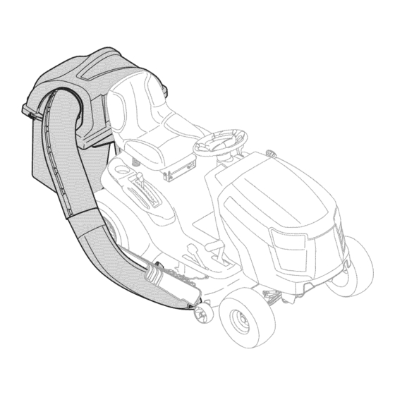
TWO BIN BAGGER
Model No. 247.240193
• Espanol, p. 18
IMPORTANT:
Read and follow all Safety
Rules and Instructions before
operating this equipment.
Sears Brands Management Corporation, Hoffman Estates, IL 60179 U.S.A.
Visit our website: www.craftsman.com
®
For answers to your questions about
this product, call:
1-800-659-5917
Craftsman Tractor Help Line
7 am - 7 pm CT, Mon. - Sun.
Form No. 769-08766
(February 1, 2013)
Advertisement
Chapters
Table of Contents

Related Manuals for Craftsman 247.240193


Summary of Contents for Craftsman 247.240193
- Page 1 Operator’s Manual ® TWO BIN BAGGER Model No. 247.240193 • Espanol, p. 18 IMPORTANT: For answers to your questions about this product, call: Read and follow all Safety 1-800-659-5917 Rules and Instructions before operating this equipment. Craftsman Tractor Help Line 7 am - 7 pm CT, Mon.
-
Page 2: Table Of Contents
FOR ONE YEAR from the date of purchase, this product is warranted against any defects in material or workmanship. A defective product will be replaced free of charge. For warranty coverage details to obtain free replacement, visit the web site: www.craftsman.com This warranty is void if this product is ever used while providing commercial services or if rented to another person. -
Page 3: Safe Operation Practices
SAFETY INSTRUCTIONS WARNING DANGER This symbol points out important safety instructions which, if not This machine was built to be operated according to the safe operation followed, could endanger the personal safety and/or property of practices in this manual. As with any type of power equipment, yourself and others. - Page 4 SAFETY INSTRUCTIONS GENERAL SERVICE • Keep all movement on the slopes slow and gradual. Do not make sudden changes in speed or direction. Rapid engagement or braking could cause • Before cleaning, repairing, or inspecting, make certain the blade(s) and all the front of the machine to lift and rapidly flip over backwards which could moving parts have stopped.
-
Page 5: Slope Guide
SLOPE GAUGE... - Page 6 CONTENTS OF CARTON Before beginning installation, remove all parts from the carton to make sure everything is present. Carton contents are listed and shown below. Two hardware packs are included in this kit and are detailed on the following page. •...
-
Page 7: Contents Of Carton & Hardware Packs
CONTENTS OF HARDWARE PACKS Este kit de césped se suministra con dos números de referencias de clientes encerrados. Se recomienda consultar los números de referencia de los clientes contra las siguientes ilustraciones. Las cantidades de cada artículo se indica entre paréntesis, mientras que el número aparece junto a cada ítem. Hardware Pack for 689-00312 Hardware Pack 689-00313 723-04008A... -
Page 8: Assembly And Installation
ASSEMBLY AND INSTALLATION Assembling the Mounting Hardware Assemble Mounting Brackets To assemble the bagger mounting assembly, locate the hitch bracket kit and follow If not already installed by the factory, install a shoulder bolt from your these steps: hardware pack onto each bracket, securing them with flange lock nuts also Attach the two hitch side brackets to the universal rear attachment bracket using included in the hardware pack included with these brackets. - Page 9 ASSEMBLY AND INSTALLATION Mount Assembly on Tractor Install the upright support bracket onto the mounting assembly on the tractor by hooking it over the cross mounting bracket and aligning it with Install the mounting assembly on the tractor as follows: the mounting hole indicating the deck size your machine is equipped with, as shown in Figure 7.
- Page 10 ASSEMBLY AND INSTALLATION Install the hanger assembly onto the upright support bracket using a Install the grass catcher cover onto the bag support assembly, as seen in carriage bolt (710-0276) and wing knob (720-04122) from hardware pack Figure 11. The grass catcher cover goes inside of the two mounting tabs on 689-00312.
- Page 11 ASSEMBLY AND INSTALLATION Install both grass bags onto the bag support assembly by inserting the front edge in first (1), as seen in Figure 15, and setting the back edge down (2) until it fits into the assembly. Figure 13 Flip seat forward.
- Page 12 ASSEMBLY AND INSTALLATION Installing the Deck Chute On Tractors with Older Deck Configurations Note: Determine if your deck is a newer model, or an older model. Refer to Install the rubber chute strap, from hardware pack 689-00313, onto the the upper inset of Figure 17. If your deck has a mounting stud present, then chute elbow using the clevis pin (711-05063), washer (736-0204) and Bow-tie you have a newer deck model and you would follow the instructions below.
- Page 13 ASSEMBLY AND INSTALLATION Installing the Upper Chute Tube Peel the backing off of the self-adhesive foam strip (721-04388) that has been included within your Contents of Carton. Apply it to the upper chute, flush against the flange as shown in Figure 22. Flange Figure 20 Note: On decks without deck wheels, hook the retainer strap into the hole...
- Page 14 ASSEMBLY AND INSTALLATION With the ability now to wiggle the discharge chute tube back and forth, slide it over the chute elbow mounted on the cutting deck, as shown in Figure 24. Figure 24 Continue to work the discharge chute down over the chute elbow until the groove on the discharge chute aligns with the upper chute support, as seen in the inset of Figure 25.
-
Page 15: Operation
OPERATION Bagger Operation Empty the grass clippings at a proper disposal site. Grasp the handle at the bottom of the bag with one hand, and with the other hand steady the bag, NOTE: When both grass bags are full, place the tractor on a firm, level surface, and empty the contents. -
Page 16: Parts List
PARTS LIST Mounting Bracket Kit... - Page 17 PARTS LIST CRAFTSMAN TWO BIN BAGGER Model No. 247.240193 To purchase replacement parts, call 1-800-469-4663 Ref. Part Number Description 689-00304 Mounting Bracket Kit (Incl. ref. 16, 17, 18) 710-0276 Carriage Screw, 5/16-18 x 1.00” 711-0309A Clevis Pin, .62” Dia. 711-05049 Attachment Pin, 1/4 x 0.66 Lg.
-
Page 18: Español
Para que detalles de la cobertura de garantía obtener un reemplazo libre, visite el sitio web: www.craftsman.com Esta garantía será nula si este producto se utiliza mientras que proporciona servicios comerciales o Si alquila a otra persona. -
Page 19: Sinstrucciones De Seguridad
INSTRUCCIONES DE SEGURIDAD ADVERTENCIA PELIGRO Esta máquina fue construida para ser operada de acuerdo con La presencia de este símbolo indica que se trata de instrucciones las reglas de seguridad contenidas en este manual. Al igual que importantes de seguridad que se deben respetar para evitar con cualquier tipo de equipo motorizado, un descuido o error por poner en peligro su seguridad personal y/o material y la de otras parte del operador puede producir lesiones graves. - Page 20 INSTRUCCIONES DE SEGURIDAD Servicio general Siga las recomendaciones del fabricante sobre pesos y contrapesos de las ruedas, para mejorar la estabilidad. Antes de limpiar, reparar o inspeccionar la máquina, Haga que todos los movimientos en las pendientes sean compruebe que las cuchillas y todas las piezas móviles se lentos y graduales.
- Page 21 PENDIENTE DE CALIBRE...
-
Page 22: Contenido De La Caja
CONTENIDO DE LA CAJA Antes de comenzar la instalación, quite todas las piezas de la caja para asegurarse de que todo está presente. Contenido de la caja se enumeran y se muestra a continuación. Dos paquetes de hardware se incluyen en este kit y se detallan en la página siguiente. •... - Page 23 CONTENIDO DEL PAQUETE DE HERRAJES Este kit de colector de hierba viene con dos números de referencia de cliente adjunto. Por favor revise sus números de referencia de cliente contra las siguientes ilustraciones. Las cantidades para cada artículo aparece entre paréntesis mientras que el número de pieza cotiza cerca de cada elemento. Hardware Pack for 689-00312 Hardware Pack 689-00313 723-04008A...
-
Page 24: Montaje E Instalación
MONTAJE E INSTALACIÓN Ensamblar el Hardware de montaje Armado de las ménsulas de montaje Instale un perno con reborde del paquete de elementos en cáda ménsula, Para armar la unidad de montaje de la embolsadora, localice el kit de la ménsula de ajustándolos con las tuercas de seguridad con brida que también se enganche y siga estos pasos: encuentran en el paquete. - Page 25 MONTAJE E INSTALACIÓN Montaje en el Tractor Instalar la abrazadera de soporte vertical sobre el conjunto de montaje en el tractor y lo engancha en cruz sobre el soporte de montaje y la alineación con Instale el montaje en el tractor como sigue: el orificio de montaje que indica el tamaño de la cubierta está...
- Page 26 MONTAJE E INSTALACIÓN Instale el conjunto del gancho en el soporte de soporte vertical con un perno Instale la cubierta de recogedor de hierba en el conjunto de soporte de la de carro (710-0276) y el pomo de mariposa (720 a 04.122) de hardware bolsa, como se ve en la Figure 38.
- Page 27 MONTAJE E INSTALACIÓN Instale ambas bolsas de hierba en el conjunto de soporte de bolsa insertando el borde delantero en primera (1), como se ve en la Figure 42, y bajar el borde posterior (2) hasta que encaje en la Asamblea. Figure 40 Mueva el asiento hacia adelante.
- Page 28 MONTAJE E INSTALACIÓN Instalación del conducto de cubierta En los tractores con mayores configuraciones de cubierta Nota: Determine si su cubierta es un modelo nuevo, o un modelo antiguo. Instale la correa de conducto de goma, del paquete de tornillería 689-00313, Consulte el recuadro superior de la Figure 44.
- Page 29 MONTAJE E INSTALACIÓN Instalación del tubo de conducto superior Desprenda el respaldo de la tira de espuma autoadhesiva (721-04388) que ha sido incluida dentro de su cartón de contenido. Aplica a la tolva superior, al ras contra el reborde como se muestra en la Figure 49. Flange Figure 47 Nota: En cubiertas sin ruedas de cubierta, enganchar la correa de retención...
- Page 30 MONTAJE E INSTALACIÓN With the ability now to wiggle the discharge chute tube back and forth, slide it over the chute elbow mounted on the cutting deck, as shown in Figure 51. Figure 51 Continue to work the discharge chute down over the chute elbow until the groove on the discharge chute aligns with the upper chute support, as seen in the inset of Figure 52.
-
Page 31: Operación
Operación Funcionamiento de la embolsadora Eliminar los cubos de la hierba por levantarlas hasta (1 en la Figure 54) y fuera de la asamblea de apoyo bin (2). NOTA: Cuando los dos cubos para césped estén llenos, coloque el tractor sobre una superficie firme y nivelada, desenganche la toma de fuerza (PTO), apague el motor del tractor y coloque el freno de estacionamiento. - Page 32 Notes Page This page intentionally left blank. Use this page to make any notes regarding your bagger.
Need help?
Do you have a question about the 247.240193 and is the answer not in the manual?
Questions and answers