Table of Contents
Advertisement
Quick Links
E L E C T R O N I C
R E V I S I O N
R E V I S I O N
E L E C T R O N I C
C O N T R O L L E D
C O N T R O L L E D
CORPORATE OFFICE
www.
1020 Owen Loop South
rosenaviation
Eugene, OR 97402
1-888-668-4955
.com
Fax (541) 342-4912
Document # 9002751 Rev G
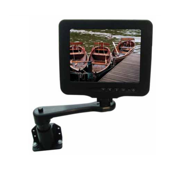
6.5
DISPLAY
DISPLAY
6500
Compliant to DO-160D
SlimLine
Model Number
6500
www.
rosenaviation
.com
Advertisement
Table of Contents

Related Manuals for Rosen Aviation SlimLine 6500 Series


Summary of Contents for Rosen Aviation SlimLine 6500 Series
- Page 1 SlimLine Model Number 6500 DISPLAY DISPLAY E L E C T R O N I C R E V I S I O N E L E C T R O N I C R E V I S I O N C O N T R O L L E D C O N T R O L L E D 6500...
-
Page 2: Table Of Contents
Table of Contents Introduction and Display Overview ....3 Pinouts ..............4 Installation Guidelines ........4 Operation ..............5 Technician Mode..........11 Troubleshooting ..........13 Technical Support ..........14 Specifi cations ............15 Disclaimer ............16 E L E C T R O N I C R E V I S I O N C O N T R O L L E D 6.5”... - Page 3 1020 Owen Loop South Eugene OR 97402 541-342-3802 www.rosenaviation.com...
-
Page 4: Introduction And Display Overview
Introduction and Display Overview Introduction and Display Overview Welcome to the 6500 Technical Manual for the 6.5” LCD display. This manual provides information for the following: • Pinouts • Installation • Operation • Technician Mode • Troubleshooting • Specifi cations The 6500 base model includes the following features: •... -
Page 5: Pinouts
Documentation, and then click on Technical Drawings & Pinouts. Search options include searching by model number or browsing by category. Drawings are provided to assist in the installation process. Pay close attention to dimensions and rotations when considering installation requirements. Rosen Aviation Page 4... -
Page 6: Operation
Operation Operation Ensure that when plugging the arm into the base receptacle, the set screw in the base follows the arm’s keyed slot and the connection is not forced. Round Style Plug-In: Slot Set Screw Rectangular Style Plug-In: Ensure that when plugging the arm into the base receptacle, the arm’s slot faces toward the release button (as shown) and... - Page 7 Status LED: The Status LED shows red when the display is in standby mode, green when the display is active, and amber when the Select Switch is pressed. Power ON/OFF: Press this button to turn the display ON or OFF. Rosen Aviation Page 6...
- Page 8 Operation On Screen Display (OSD) Main Menu The On Screen Display (OSD) provides a set of menus that enable users to adjust or view screen setup features. Some Main menu selections lead to submenus with additional setup options. Press the OSD ON/OFF button to view the Main menu.
- Page 9 SW Rev This option displays the current software revision Power Cycles This option displays the number of times power has been cycled Source This option displays the current selected video standard (NTSC/ PAL/ SECAM) continued... Rosen Aviation Page 8...
- Page 10 Operation Monitor Info Sub-Menu Options Continued... Description Temperature Menu Scroll to this selection’s sub-menu to view monitor temperature information (shown below) Signal Level This option will show Low, Good, or High. If the signal shows Low or High, adjust the video level at the source Back Select this option to return to the...
- Page 11 *If an Over Temp or Under Temp shut down occurs, Temp Shutdown is shown on the OSD for approximately 30 seconds, and then the display shuts off until the temperature reaches acceptable temperature limits. The display will then automatically turn back on. Rosen Aviation Page 10...
-
Page 12: Technician Mode
Technician Mode Technician Mode Technician mode provides the ability to customize and restrict access to the Main menu for specifi ed options. This section describes how to enter, enable and disable options, and exit Technician mode. Entering Technician Mode Complete the following list to enter Technician mode: Apply 28V to the display and wait until the status LED turns green (if the display is in auto-off, press the power ON/OFF button). - Page 13 On Color Off Tint Off Sharpness Off Backlight Off Advanced Exiting Technician Mode To exit the Technician mode, simply turn the power off and on again either with the power button or through the 28V supply. Rosen Aviation Page 12...
-
Page 14: Troubleshooting
Troubleshooting Troubleshooting If the monitor does not function properly, refer to the following troubleshooting table for symptoms and possible solutions before contacting Rosen fi eld support. Notes: • Always use an oscilloscope to verify the video signal • Always use a multimeter to verify voltages •... -
Page 15: Technical Support
SECAM to PAL video when switching standard, press the Select switch between SECAM and Technical Support For fi eld support or to order parts, contact Rosen Aviation Displays at: 1-888-668-4955 or visit us at: www.rosenaviation.com Rosen Aviation Page 14... -
Page 16: Specifi Cations
Specifi cations Specifi cations LCD Performance Screen Resolution (pixels) 640 w x 480 h Display Viewing Area 5.14 x 3.84 in Viewing Angle ( At contrast ratio 10:1 ) Horizontal ±50º Vertical +35º up -45º down Contrast Ratio 300:1 (Typical) Backlight Lamp Life 30000 hours continuous operation... -
Page 17: Disclaimer
Specifi cations are subject to change without notice. Rosen reserves the right to make changes - without notifi cation to buyer - to materials or processing that do not affect compliance with any applicable specifi cations. Rosen Aviation Page 16...
Need help?
Do you have a question about the SlimLine 6500 Series and is the answer not in the manual?
Questions and answers