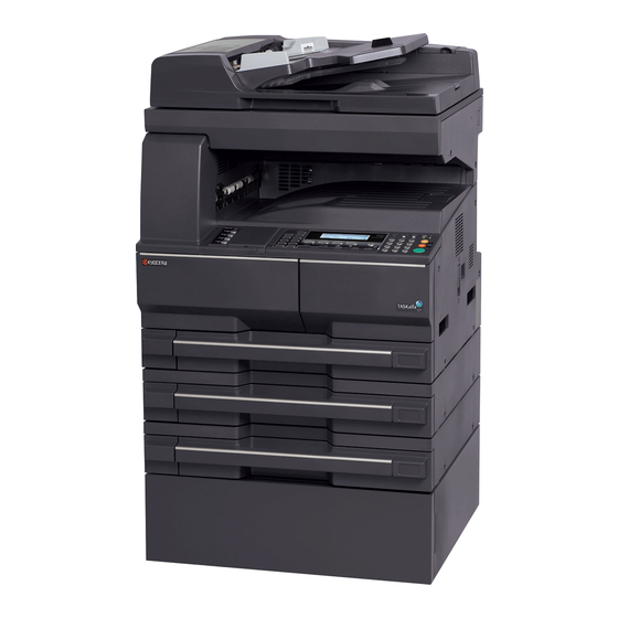
Kyocera TASKalfa 181 Installation Manual
Fax system (r)
Hide thumbs
Also See for TASKalfa 181:
- Service manual (356 pages) ,
- Operation manual (276 pages) ,
- User manual (93 pages)
Summary of Contents for Kyocera TASKalfa 181
- Page 1 INSTALLATION GUIDE GUIDE D’INSTALLATION GUÍA DE INSTALACION INSTALLATIONSANLEITUNG GUIDA ALL’INSTALLAZIONE 安装手册 設置手順書 FAX System (R)
- Page 3 D Plate spring..........1 K One-touch sheet English 120 V specification ........3 E Wire ............1 230 V specification ........7 Supplied parts F Upper plate ..........1 L One-touch label sheet ........1 A Fax control circuit board assembly ..1 G Lower plate ..........
- Page 4 Option Be sure to remove any tape and/or cushioning Procedure material from supplied parts. Q Memory module DIMM (32 MB) ....1 Turn the MFP’s power switch to OFF and unplug the MFP from the power supply before installing the fax system. Option Veillez à...
- Page 5 Install the (optional) Memory module DIMM (32MB) Removing the covers 1. Insert the memory module DIMM (Q) at an angle into the memory slot (2) so that the notch (1) 3. Remove the 5 screws (4) from the rear side of the memory DIMM (Q) is positioned to the projection (3) of the memory slot (2) on the fax of the machine to remove the cover (5).
- Page 6 4. Remove the screw (6) to remove the Installing the plate spring Attach the fax control circuit board assembly. mounting plates ((7) and (8)). 5. Use the M3 x 8 screw (C) to attach the plate 6. Plug the yellow connector on the wire (E) spring (D) to the shielding cover.
- Page 7 7. Plug the white connector on the wire (E) into YC10 (10) on the engine 8. Fit the 2 hooks (11) on the fax control circuit board assembly (A) into circuit board. the latch (12) in the shielding cover. 7. Raccordez le connecteur blanc du câble (E) à YC10 (10) de la carte de 8.
- Page 8 9. Secure the fax control circuit board assembly (A) using the five M3 x 8 screws (C). 10. Remove the screw (14) from the machine. When fastening the lower-right screw (C*), take care not to pinch the wire (13) 9. Fixez l'ensemble de carte à circuits de commande de fax (A) à l'aide de cinq vis M3 x 8 (C). 10.
- Page 9 11. Attach the upper plate (F) using an M3 x 8 screw (C) and another Connect the telephone line to the line terminal. screw (14). 14.Insert the modular connector cable (16) to the line terminal (15) to 12. Attach the lower plate (G) using two M3 x 8 screws (C). connect it to the telephone line.
- Page 10 Installing the operation section sheet 17.Lift the three pawls (20) and remove the operation section sheet cover 15. Insert a flat-head screwdriver into the latch and remove the cover (18). (21). 16. Remove the left cover of the operation section (19). Repose de la feuille de la section d'opération 17.Soulever les trois cliquets (20) et retirer le couvercle de la feuille de la 15.
- Page 11 18. Remove the operation section sheet (22) and replace it with the 19.Refit the operation section sheet cover (21) removed in step 17 by operation section sheet (H) for fax of the corresponding language. inserting the 2 pawls (23) on the right side of the cover into their respective slots.
- Page 12 20. Refit the cover (18) removed in step 15 by Attach the one-touch securing sheet. inserting the pawl (24) into its slot. 21. Remove the release paper from the one-touch securing sheet (I). 22. Adhere the one-touch securing sheet (I) on the base frame of the one-touch key so that it sticks fast to the surface while matching the top surface to the top left corner and firmly pressing the whole area down as shown in the illustration.
- Page 13 Attach the fax label. Attach the fax plate.(120 and 230 V specifications only) (120 and 230 V specifications only) 25. Incurvate the fax plate (J) a little and then insert the upper and lower projections (25) to the fitting 24. Adhere the fax labels (1) to (4) of the fax parts of the operation section to attach.
- Page 14 Attach the one-touch sheet.(120 and 230 V specifications only) Attach the alphabet labels. (except for 100 V specifications) 27. Separate the one-touch sheet (K) for the supported language into 2 28.Wipe the area above each of the numeric keys on the right side of the parts and stick them onto the respective locations on the one-touch operation panel with alcohol and stick the alphabet labels (26) from the securing sheet (I).
- Page 15 Attach the certification label (only 100V and Execute the maintenance mode. 120 V). After installation is complete, the fax control 29. Stick the FCC68 label (N) or JATE label (O) circuit board must be initialized by executing the onto the cover (5) after first cleaning the area maintenance mode U601/U602.
- Page 16 For Australia and New Zealand Attach the approval label Only Australia specification Attach the A-TICK label (R) onto the shield cover (5) after wiping the cover with alcohol . A-TICK label Only New Zealand specification Attach the TELEPERMIT label (R) onto the shield cover (5) after wiping the cover with alcohol .
- Page 17 MEMO...
- Page 18 MEMO...
- Page 19 MEMO...
- Page 20 2009. 3 303MZ56711...


Need help?
Do you have a question about the TASKalfa 181 and is the answer not in the manual?
Questions and answers