Table of Contents

Related Manuals for Craftsman 113.221720


Summary of Contents for Craftsman 113.221720
- Page 1 Save This Manual For Future Reference IOqNCH DIRECT TABLE SAW FOR YOUR . assembly SAF TY. . operating BEAD ALL INSTRUCTIONS • repair parts CAREFULLY Sold by SEARS, ROEBUCK AND CO., Chicago, iL. 60684 U.S.A. Part No. SP5537 Pr_n._ea in U.S,A,...
-
Page 2: Warranty
WARRANTY SERVICE iS AVAILABLE BY SIMPLY" CONTACTING "irHENEAREST SEARS SERV_E CF_NTER/DEPARTMENTTHROUGHOUT THE UN|TED STATES. THIS WARRANTY APPUES ONLY _IILETHiS PRODUCT IS USED IN THE UNITED STATES. This warranty gives you specific legal rights, and you may als.= have other rig hts which vary from state to state. - Page 3 E. REMOVE ADJUSTING KEYS AND WRENCHES. jewelry (rings, wristwatches). They can get Form habit of checking for and removing keys and caught and draw you into moving pads. adjusting wrenches from tool before turning it on. 2. Wear nonslip footwear. F.
-
Page 4: Additional Instructions For Rip Type Cuts
3. Set the cutting tool as low as possible for the cut you're planning. 4. KEEP CHILDREN AWAY. All visitors should be kept a safe distance fromwork. Make sure bystanders are uselength stops against it. it must be freeto clear of the saw and workpiece. move. -
Page 5: Additional Instructions Fgr Cross Cut Type Cuts
BEFORE STARTING 2. An auxiliary wood facing attached to the Miter Gauge can help prevent workpiece twisting and throwbacks. 1. To avoid kickbacks and slips into the blade, make Attach it tothe holes provided. Make the facing !ong sure the Rip Fence is parallel to the sawblade. enough and big enough to support your work. -
Page 6: Glossary
glossary of terms for woodworking thepart of the workDiece which will be. or has been_ cut by the blade. Trail , the =n a npping The distance thai [ne up oi [ne sawo_aoe _oo_n_soem to r set) outward from the face of the blade. Workpiece Throw-Back The item on which the cutting operation is being done. -
Page 7: Table Of Contents
WARNING: To help avoid electric Shock, the green grounding lug extending from the adapter GROUNDING permanent ground must be connected tO a such properly grounded as to a outlet box. properly grounded, outlet boxes if you are not properly grounded, sure the outlet box is have H PLUG... -
Page 8: List Of Loose Parts
COMBINATION SQUARE MUST BE TRUE. STRAIGHT EDGE OF BOARD Medium Screwdriver 7/16, 1/2,11/16 3/4" THICK. THIS EDGE MUST STRAIGHT, DRAW LIGHT LINE % BE PERFECTLY BOARD ALONG THIS EDGE, ',, \ #2 Phi ips Screwdriver Long Nose P ers x.,ll "J' _ "... -
Page 9: Assembly
assembly Bag of Loose Parts Containing the following: Key, Switch ........... Nut, Square 1/4-20 ........Screw, Soc. Set 1/4x 7/8 ......4 Washer, Flat 17/64 x 9/16 x 3/64 ....4 Lockwasher, External 1/4 ......4 Lockwasher, External #8 ....... 2 Nut, Hex 1/4-20 .......... - Page 10 ge in saw table t_y. b sligl_ly using pi_rs...
-
Page 11: Checking Heeling Or Parallelism Of Sawblade
CHECKING HEELING OR PARALLELISM OF SAWBLADE TO ?4_TER GAUGE GROOVE M_RK "x o_ Whi_e cutting, the materia_ must _:_e _ _ _Vai_h_ _ T_3OTN PARALLEL to the SAWBLADE there,'o_e_t;<_th tr_eMi_er Gauge GROOVE and the R_P F_NCE m_Jst b e PARAL_ LEL to the SAWBLADE. - Page 12 if It does - alternately tighten other three screws slowly.
-
Page 13: Adjusting Bevel Pointer
ADJUSTING 90 ° BEVEL STOP /BLADE 1. On the stop bracket are two 10-32 pan head screws which set 90 ° stop position. If condition A exists, the two screws need to be turned clockwise to obtain 90= setting. If condition B exits, the screws should be turned counterclockwise. -
Page 14: Checking 45° Bevel Stop
assembly CHECKING 45° BEVEL STOP 1. Turn Elevation Handwhee counterc ockwise to raise blade as high as it will go. 2. Turn Bevel Handwheel clockwise to tilt blade to 45_. 3. Lay head of combination square on the blade of square, as ustrated, and place head against the blade. -
Page 15: Installing Table Extensions
iNSTALLiNG TABLE EXTENSIONS 1. Lower blade to below the table top. 2. From among the loose parts, find the following hard- ware: * 14 Flat Hd. Socket Screws 1/4-20 x 5/8 FLAT HEAD SOCKET SCREW 1/4-20 X 5/8 Items marked with an asterisk {*) are shown actual size. FLAT HEAD 3. -
Page 16: To Raise Extension
TO RAISE EXTENSION and rear. a=vTl_l @ar_DJ 3. Check height with square and tighten A B and C. 4. Repeat for left extension. TO LOWER EXTENSION ,I ,Jll,l.l.', l,i.I.=,l..l,t.l.l,l.i.l,l,l.J,l,w, I,i ,I,[,] 2_ Tighten screws A, B, and C on top of table extension to lower extension even with table top front and rear. -
Page 17: To Raise Outer Edge Of Extension
TO RAISE OUTER EDGE OF EXTENSION 1. Loosen screws C, D, and G on right extension. 2. Tighten screws B, E, and F until table extension is L..._J ------ level. EXTENSION 3. Snug down screws C, D, and G. 4. Repeat for left table extension. ALiGNiNG TABLE EXTENSIONS... -
Page 18: To Move Outer Edge Of Extension Forward
i:li i '! | iili llil Check left extension. 5. Check left extension. • ii1,1 I I I I I I I t t tl't'l'l'='l'J'l'l'l'l'l'l'l 6. Adjust left extension in same manner. LEVELING CENTER OF EXTENSION 3"0 TABLE 1. Locatetwo (2) 1/4-20 x 7/8 sockethead set screws and installon bottomsideoftable. - Page 19 SQUARE _..,_ _=./ SPREADER SUPPORT TRUSS HEAD SPREADER BRACKET SCREW 2. Parts are assembled as shown in illustration. Follow IN. LONG _"__/_ SPREADER CLAMP steps below. SOCKETHEAD 3. MAKE SURE TH E BLADE IS ALL THE WAY UP AND SETSCREW _---__ 8 "_, _ WING NUT...
-
Page 20: Attaching Rip Fence
SPACE EQUAL TO APPROX, 3 THICKNESSES OF PAPER KERF WOOD ALIGNING SPREADER IMPORTANT: To work properly, the Spreader must lways be adj ust ed so t he cut wo rkpiece w ill pass on ither side of the Spreader without binding or skew- - .. -
Page 21: Aligning Rip Fence
ALiGNiNG RiP FENCE MUST LINE UP WITH MITER SLOT FRONT AND REAR backs and jams. To avoid injury, follow these WARNING: A mlsailgned Fence can cause kick- instructions until fence is properly aligned. 1. Hold head of Rip Fence and slide on table until the edge of the fence lines up with the right miter slot. - Page 22 6. Move the measuring tape under head of Rip Fence untilthe 10 inch mark on the measuring tape is lined up with the right edge of the Rip Fence head. RiP FENCE H__ "O" INCH 7_ Hold the measuring tape in this position with one hand, while using the other hand to peel off approxi- mately one inch of protective coating from underside of tape on the left end ("0"...
-
Page 23: Adjusting M_Ter Gauge
13. Use a tape rule to measure 10 inches out from the left side of the blade. Position the Rip Fence so the right side of the fence is at this 10 inch mark. RIGHT SiDE OF FENCE 14. Lock Rip Fence in this position. 10"... - Page 24 assembly with them. correctly. FRONT SIDE FRONTOF TABLESAW CATALOG NO. 9-22244 LEG SET (not included with table saw) Recommended hardware (not included) for mounting HEX HEAD BOLT table saw to teg set: 1/4-20 × 1-1/2 HEX NUT 1/4-20 *4 Rex Hcl Bolts, 1/4-20 x 1-1/2 ©...
-
Page 25: Getting To Know Your Saw
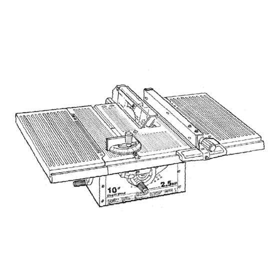
getting to know your saw 5 BLADE GUARD SPREADER 6 TABLE iNSERT RiP FENCE TABLE EXTENSION 3 TiLT HANDWHEEL BEVEL SCALE 1 ON-OFF SWITCH POWER CORD ON-OFF SWITCH sure the blade guard is correctly installed and CAUTION: Before turning switch "ON", make] operating properly. -
Page 26: Elevation Handwheel
getting to know your saw ELEVATION HANDWHEEL... elevates or Iowersthe blade. Turn counterclockwise to elevate, clockwise to lower. TILTHANDWHEEL...tiltsthebladeforbevel A. Lower the blade below the table surface cutting. Turn counterclockwise to tilt toward eft, B. Raise Blade Guard. clockwise to tilt toward right. C. -
Page 27: Removing And Installing Sawblade
PHILLIPS REMOVING AND iNSTALLiNG BLADE INSERT HEAD SCREW SAWBLADE WARNING: To avoid Injury due to accidental start, push switch "OFF" and remove plug from power source outlet before removing or installing sawblade. NOTE: When installing the blade, make sure the upper \\\_\\_ saw teeth are pointing toward the front of the saw and that the blade and collars are clean, and free from any burrs. -
Page 28: Basic Saw Operation
basic saw operations THESE EDGES BE PARALLEL 3/4 PLYWOOD WORK HELPERS Before cutting any _ on your saw, study all of the "Basic Saw Operations." Notice that in order to make some of the cuts;, it is necessary to use certain devices, "Work Helpers", like the Push Stick, the Push Block and the Auxiliary Fence/ Work Su_, which you can make yourself. - Page 29 safety instructions for basic saw operations 6. Any power saw can throw foreign objects into 2. Choose the right blade or cutting accessory for the eyes. This can cause permanent eye darn- the material and the type of cutting you plan to age.
- Page 30 safety instructions for basic saw operations b. Neverconfinethe piece being cut off. That is, 1. Before actually cutting with the saw, watch it while it the piece NOTagainstthe Fence, MiterGauge runs for a short while. If it makes an unfamiliar noise orfixture.
-
Page 31: Using The Miter Gauge
basic saw operation -using the miter gauge can help prevent workpiece twisting and throwbacks. The MITER GAUGE IS USED when CROSSCUTTING, Attach it to the holes provided. Make the facing long MITER CUTTING, BEVEL CUTTING, COMPOUND MI- enough and big enough to support yourwork. Make TER CUTTING, DADOING... -
Page 32: Repetitive Cutting
basic saw operations REPETITIVE CUTTING 1. NEVER USE THE RiP FENCE AS A LENGTH STOP BECAUSE THE CUT OFF PIECE COULD BIND BETWEEN THE FENCE AND THE BLADE CAUS- iNG A KICKBACK, 2_ When making repetitive cuts shoder than 6 inches, c amp a block of wood 3 inches longto the table to act as a length stop. -
Page 33: Bevel Crosscutting
WORKPIECE BEVEL CROSSCUTTING BEVEL CROSSCUTTING is the same as crosscutting except that the wood is also cut at an angle, other than TABLE 90 ° with the flat side of the wood. Adjust the blade to the desired angle. Use the Miter Gauge in the groove to the RIGHT of the blade. -
Page 34: Ripping
basic saw operations RIPPING Rmpplng s known as a cutting operation along the length wORKP!ECE of the workpiece. Position the Fence to the desired WIDTH OF RiP and lock in place, Before starting to rip, be sure: 1. Rip Fence is parallel to sawblade. 2. - Page 35 When WIDTH OF RiP is 1/2 inch to 2 inches, the Push Stick CANNOT be used because the Guard will inter- fere. USE the Auxiliary Fence/Work Support and Push B ck. Attach Auxiliary Fence/Work Support to Rip Fence with two i'C" clamps. AUXILIARY FENCE WORK...
-
Page 36: Using Featherboards For Thru-Sawing
FEATHERBOARD USING FEATHERBOARDS FOR THRU SAWING "C" CLAMPS backs. piece. i WARNING: Make sure the Featherbeard againsl I the edge presses only on the uncut position (in front of tl_e blade}, it might otherwise pinch the blade in the kerr and cause a kickback. Before starting the operation (switch "OFF"... -
Page 37: Using Featherboards For Non Thru-Sawing
USING FEATHERBOARDS NON- THRU SAWING FEATHERBOARD Featherboards are NOT employed during non thru- sawing operations when using the Miter Gauge. "C"CLAMPS USE FEATHERBOARDS FOR ALLOTHER NON THRU- SAWING OPERATIONS (when Sawblade Guard must be removed). Featherboards are used to keep the work in contact with the Fence and table as shown, and to stop kickbacks. -
Page 38: Ploughing
I source outlet before maintaining or lubrl_ing I your saw. Do not allow sawdust to accumulate inside the saw. Frequently clean your cutting toolswith Craftsman Gum and Pitch Remover. slide more freely. itthe power cord is worn, cut, or damaged in anyway, have it replaced immediately. -
Page 39: Wiring Diagram
1. Elevation guide slot and pivot, 2. Elevation screw threads and support bearings. 3. Bevel screw threads and support bearings. (First clean with Craftsman Gum & Pitch Remover.) 4. Bevel and elevation link pivot points. GUARD 5. Cradle pivot pin bearing points. -
Page 40: Trouble Shooting
sears recommends the following accessories ITEM CAT. NO. Saw Blades ..........See Catalog Sears may recommend other accessories not listed Dado insert ............. 9-22273 in manual Taper Jig ..........See Catalog See your nearest _ears Store or Catalog Department Dado Set ..........See Catalog for other accessbrles. -
Page 41: Maintenance
TROUBLESHOOTING - MOTOR NOTE: Motors used on wood working too_s particularly susceptible to the accumulation of sawdust and wood chips and should be blown out or %,acuumed" frequently to prevent interference with normat rr_otor ventilation. REMEDY TROUBLE PROBABLE CAUSE 1 .__motor checked by qualified service techni- Excessive noise. -
Page 42: Repair Parts
repair parts... - Page 43 "0 .- _ E._N E !_,,...
- Page 44 PARTS LIST FOR CRAFTSMAN 10 INCH TABLE SAW MODEL NO. 1113.221720 ÷.. FIGURE 2 - GUARD ASSEMBLY KEY I NO.i 62810 62410 Pin, 1/4 x 1-3/64 62519 Spring Pawl 62520 Spacer, Paw! 62974 . Pawl STD551012 Washer 17/64 x 1t2 x 1/32...
- Page 45 PARTS LIST FOR CRAFTSMAN 10 iNCH TABLE SAW MODEL NO. 113,221720 FIGURE3 FENCE ASSEMBLY PART DESCRIPTION 62693 Plug, Button 62692 Knob (Includes Key No. 1) STD551031 * Washer, 21/64 x 5/8 x 1/32 62996 Head, Fence STD551231 * Lockwasher, External 5/16 60078 Screw, Hex Hd., 5/16-18 ×...
- Page 46 PARTS LiST FOR CRAFTSMAN 10 iNCH TABLE SAW MODEL NO. 113.221720 i! _ • i _ S2693 Pleg; B_0n 62999 i E_b (i_¢iOdes Key #i) 1/32 _724 ii_r 7 ,605_ 820863 ter Gauge 62175 Pi ni Mite_ Pivot...
- Page 47 notes...
- Page 48 10-INCH DIRECT DRIVE TABLE SAW Now that you have purchased your 10-inch direct drive table saw, should a need ever exist for repair parts or service, simply contact any Sears Service Center and most Sears, Roebuck and Co, stores. sure to provide all pertinent facts when you call or visit.
Need help?
Do you have a question about the 113.221720 and is the answer not in the manual?
Questions and answers
How do I make a craftsman table saw reverse direction