Table of Contents
Advertisement
SAVE
THIS MANUAL
FOR FUTURE
REFERENCE
SEARS
owners
manual
MODEL
NO.
113.244513
CAUTION:
Read GENERAL and
ADDITIONAL
SAFETY
IN ST
R
UCTIO
N
S
caref
ully
Serial
Number
Model and serial
number may be found
at the right-hand side
of the
frame.
You should record both
model and serial
number in a safe place
for future
use.
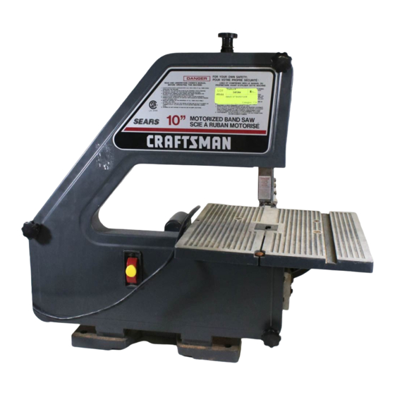
CRRFTSMf,]I
7O-rNcH
BAND SAW
o
assem bly
o
operating
o
repait parts
Sold
by
SEARS, ROEBUCK
AND
CO., Chicago,
IL.
60684
U.S.A.
Part No.
SP5100
Advertisement
Table of Contents

Related Manuals for Craftsman 113.244513


Summary of Contents for Craftsman 113.244513
- Page 1 SAVE THIS MANUAL FUTURE REFERENCE SEARS owners manual MODEL 113.244513 Serial Number Model and serial number may be found at the right-hand side of the frame. You should record both model and serial number in a safe place for future use.
- Page 2 FULL ONE YEAR WARRANTY ON CRAFTSMAN BAND SAW one year lrom the date within material or workmanship, Sears WARRANTY SERVICE IS AVAILABLE BY SIMPLY CONTACTING THE NEAREST SEARS SERVICE CENTER/DEPARTMENT THROUGHOUT THE UNITED THIS WARRANTY APPLIES ONLY WHILE THIS PRODUCT IS USED IN THE UNITED This warranty gives you specilic legal rights, and you may also state to state.
- Page 3 BEFORE USING THE SAW: WARNING: AVOID MISTAKES RESULT SERIOUS, PERMANENT DO NOT PLUG THE SAW IN UNTIL THE STEPS HAVE BEEN COMPLETED: Assembly alignment. l-earn the function and proper use guide switch. upper blade guide tension adlusting guide.
- Page 4 "ON" before Never everything except or support devices off the WHENEVER SAW IS RUNNING WARNING: ALLOW...
- Page 5 POWER SHOCK PARTICULARLY WHEN USED DAMP LOCATIONS CLOSE ELECTRICAL SHOCK OCCURS THERE POTENTIAL SUCH YOUR HANDS CONTACTING SAW BLADE. power cord is worn or cut, or damaged in replaced immediately. way, have unit is for use on Your looks like below r-<t...
- Page 6 WARNING: FOR YOUR OWN SAFETY, CONNECT PLUG UNTIL ALL ASSEMBLY STEPS ARE COMPLETE, AND YOU HAVE READ AND UNDERSTAND SAFETY Model 113.244513 one carton. Separate check each item with illustration and "Table Loose Parts". Make certain tFrm-- ed for, before discarding any packing material.
- Page 7 5'l6" Insert ali four screws and tiohten. alternate method a mounting board. The board should band saw icient size to avoid tipping of saw while suff use. Any good grade with 3/4" minimum thickness is recommended. (Thinner chipboard can break.)
-
Page 8: Installing The Table
"C" or more clamps to the table too that slide trunnion all of the two (2\ 17164 loose parts bag, parts. onto band saw frame frame lock knobs and washers slots trunnion WORKBENCH UPPER GUIDE ASSE TRUNNION STOTS... -
Page 9: Replacing The Blade
Locate bevel indicator cross hd. screw in loose parts Install bevel indicator and screw as using a phillips screwdriver. This unit comes with the Band Saw NOTE: installed, assembly continues on p. ing the Blade." REPLACING THE BLADE the guide bar lock... -
Page 10: Tensioning The Blade
Loosen the blade guides and separate them about 1/8". Loosen screw holding guide support and slide support of the saw, and retighten toward the rear screws. AVOID BEING WARNING: SHOULD BLADE SUDDENLY UNCOIL, SAFETY GOGGLES CAREFULLY UNCOIL THE BLADE HOLDING AT ARMS LENGTH. - Page 11 1/8" hex the set screw moves the tension wheel and forth.) B. lf moves toward the blade band saw: Turn the tracking adjustment screw clock- wise about were tightening blade moves band saw: Turn tracking se about counterclocki',' .'.e'e toosening...
- Page 12 1/32" from the GULLET of the saw blade. Tighten screw. ADJUSTING UPPER BLADE GUIDES the two screws that lock the Loosen blade guides and press the two guides evenly sides...
- Page 13 4" truss head screw, wing nut loose nto hole in table top onto the truss head screw will keep the alignment. saw cover. know your band saw 1]JUS-IING'KNOB GUIDE LOCK KNOB TABTE BTADE TABL DRIVE BELT TRUSS HEAD SCREW ---7...
- Page 14 Your band saw Tension adjusting knob will knob (clockwise) increase the tension (counter clockwise) blade. Loosening decrease the tension. (Tension lock knob will must be released). Secure cover Cover knobs cover knobs. tightening all three Blade Supports Guides .
- Page 15 This band saw wood like products only.
- Page 16 Remove Do not allow pitch accumulate blade insert, blade guides, with them Clean Craftsman Remover. thin coat of automobile-type wax Apply a table so the wood slides easily while inside surfaces Also apply wax ion.
- Page 17 Repair service is available at your cian. est Sears Store. "Trackino the Blade." Stop feeding, and back up the material slightly, until the band saw speeds Replace blade. See Assembly section "Tensioning The Blade." correct cutting technique. See Basic Band Saw Operation Section.
-
Page 18: Repair Parts
repair parts =lr, <-l v, ?l <= -)-; \g*t r \9 r.it,:_g A s-.fQ)- i1\ ; :-3 v ,- :i ;.-g ,<q 7/.-\ \_-i=... - Page 19 d o :83 E! i;;FF,*gsEi#ein+c:i E;;s.! .F$# S:!'IS5EEF3FF8FUPgFHfi38FS .::::3'n663b33333b33883b33 >: N € - O .- N :a:'. - = = s s I I <t $ $$ -<f Z<rl -o : t'44 -=ru <= I ? - s q$! rrfi =z ?o 3b 3 E: =-.-i ;t Ei.:+t€;EpF...
- Page 20 SERVICE MODEL 113.244513 HOW TO ORDER REPAIR PARTS Sold SEARS, ROEBUCK Part No. SP5100 70.'NCH BAND SAW that you have purchased Saw should exist for need ever service, simply contact any Sears Service Center and most Sears, Roebuck and Co. stores. Be sure...
Need help?
Do you have a question about the 113.244513 and is the answer not in the manual?
Questions and answers
where can i find parts for craftsman bandsaw mo.113.244513 i need part no.69167 .. upper guide assembly ..thank for any help..