
Related Manuals for Emerson Liebert NX 400V


Summary of Contents for Emerson Liebert NX 400V
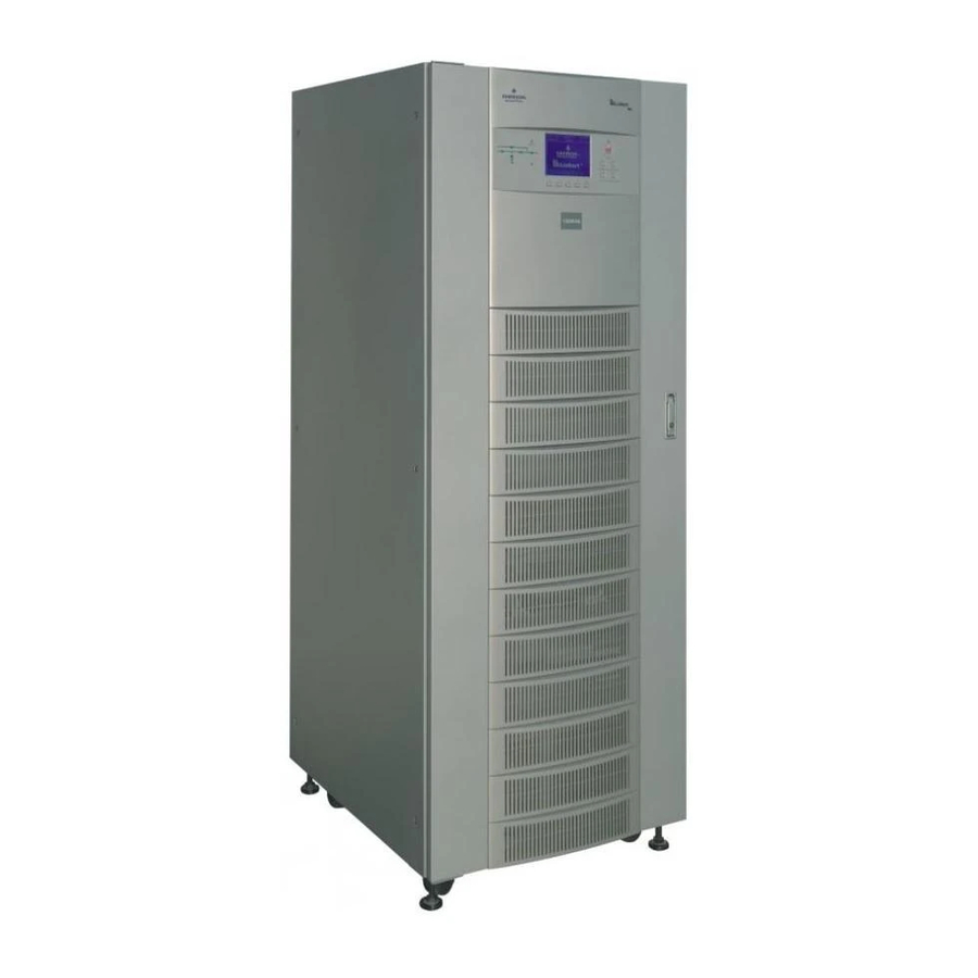
- Page 1 Liebert NX™ User Manual 50 and 60 Hz, 30-200kVA, 400V AC Power For Business-Critical Continuity...
-
Page 3: Table Of Contents
UPS I INGLE ODULE Introduction ..............3 Preliminary Checks . - Page 4 Redundant Control Power Supply Board ........
- Page 5 Modes of Operation............78 6.3.1 Normal Mode .
- Page 6 Prompt (Pop-Up) Windows........... 103 Dynamic Energy Flow Chart and UPS Help Screen .
- Page 7 Figure i Model number nomenclature ............ix Figure 1 Residual current circuit breakers (RCCB) symbols .
- Page 8 Figure 47 Front view doors open—60-80kVA NX ..........62 Figure 48 Cable terminal layout—60-80kVA NX.
- Page 9 Table 1 Maximum steady state AC and DC currents......... . . 8 Table 2 Distance from floor to connection point on the equipment .
- Page 10 Our philosophy is reflected in our mission statement “Keeping Business in Business,” and with this we strive to contribute to the growth & success of your business. Please give us your valued feedback to help us realise our mission. EMERSON NETWORK POWER viii...
-
Page 11: Figure I Model Number Nomenclature
Requires RELAYCARD-INT — — — — — (XXX: 050 or 150)- 'Specify Length in metres. Used for extension in length or dual bus arrangement between Nx and non-Nx sources' Specify number of blocks. Consult Emerson Network Power representatives for complete configuration... -
Page 13: Safety Precautions
SAFETY PRECAUTIONS This manual contains information concerning the installation and operation of this Emerson Network Power Liebert NX Uninterruptible Power System (UPS). This manual should be read before commencing installation. The UPS must be commissioned and serviced by an engineer approved by the manufacturer (or agent). - Page 14 User-Serviceable Parts All equipment maintenance and servicing procedures involving internal access requires the use of a tool and should be carried out only by trained personnel. There are no user-serviceable parts behind covers requiring a tool for removal. This UPS is fully compliant with safety regulations for equipment located in an operator accessible area.
-
Page 15: Single Module Mups Installation
This following section describes the requirements that must be taken into account when planning the positioning and cabling of the Liebert NX uninterruptible power supply and related equipment. This chapter is a guide to general procedures and practices that should be observed by the installing engineer. -
Page 16: Location
Location 1.3.1 UPS Room The UPS and its internal battery is intended for indoor installation and should be located in an envi- ronment with clean air and with adequate ventilation to keep the ambient temperature within the specified operating range (see Table 33). All models in the Liebert NX UPS range are air-cooled with the aid of internal fans. -
Page 17: Positioning
Positioning The cabinet is mounted on four casters for ease of positioning and for moving short distances. Jacking feet are provided to prevent the UPS from moving once it has been wheeled to its final position. For optimal design life, the place chosen must offer: •... -
Page 18: Clearances
1.4.5 Clearances The Liebert NX has no ventilation grilles at either side of the UPS. To enable routine tightening of power terminations within the UPS, in addition to meeting any local regulations, Liebert recom- mends providing adequate clearance in the front of the equipment for unimpeded passage of person- nel with the doors fully opened. -
Page 19: Rectifier And Bypass Input
1.5.1 Rectifier and Bypass Input Overcurrent protection must be installed at the distribution panel of the incoming main supply. The protection must discriminate with the power cables current capacity and with the overload capacity of the system (see Table 38). As a guideline, a thermomagnetic circuit breaker, with an IEC 60947-2 trip curve C (normal) for 125% of the current listed in Table 1 is suitable. -
Page 20: Table 2 Distance From Floor To Connection Point On The Equipment
Power Cables The cable design must comply with the voltages and currents provided in this section, follow local wir- ing practices and take into consideration the environmental conditions (temperature and physical support media). For cable entry terminal, refer to Figures 43, 48, 52 and 56. WARNING Before starting the UPS, ensure that you are aware of the location and operation of the external isolators that connect the ups input/bypass supply to the mains distribution panel. -
Page 21: Cable Termination
1.6.1 Cable Termination NOTE The operations described in this section must be performed by authorised electricians or qualified technical personnel. If you have any difficulties, do not hesitate to contact our Customer Service and Support Department. See the back page of this manual for contact information. - Page 22 Output System Connections 6. Connect the system output cables between the UPS output (U2-V2-W2-N terminals) and the critical load and tighten the connections to 5Nm for M6 bolts, to 13Nm for M8 bolts or to 26Nm for M10 bolts. Ensure correct phase rotation. External UPS Battery Connection (60kVA Models and Above, Option for 30-40kVA Models) Connect the battery cables between the UPS terminals (+\-) and its associated battery circuit breaker.
-
Page 23: Control Cables And Communication
Control Cables and Communication 1.7.1 Monitor Board Features Based on your site’s specific needs, the UPS may require auxiliary connections to manage the battery system (external battery circuit breaker, battery temperature sensor), communicate with a personal computer or provide alarm signaling to external devices or for Remote Emergency Power Off (REPO). The monitor board, arranged for this purpose, is located on the rear of the operator access door. -
Page 24: Dry Contacts
Dry Contacts The UPS provides input dry contacts and output dry contacts. 1.8.1 Input Dry Contacts There are several input dry contacts at the X3 slot. X3 Ancillary Control and Alarms X3 IN DRY: Environmental, Battery Ground Fault and Generator Contacts The UPS accepts external signalling from voltage-free (dry) contacts connected to finger-proof, push- in terminal X3 IN DRY. -
Page 25: Maintenance Bypass Cabinet Interface
1.8.2 Maintenance Bypass Cabinet Interface J26 and J30 are the MBC interface. Table 4 Maintenance bypass cabinet interface Name Position Description J26.1 T_IT Input transformer overtemperature (NC) J26.2 AUX_I Reserved J26.3 +12V +12V Power J26.4 Power Ground J30.1 FUSE Reserved J30.2 F_FAN Fan Fail Alarm (NC) -
Page 26: Output Dry Contacts
1.8.4 Output Dry Contacts There are three output dry contact relays at the X1 slot (see Figure 4 and Table 6) NOTE All auxiliary cables of terminal must be double-insulated. Wire should be 0.5-1.5mm (16-20AWG) stranded for maximum runs between 25 and 50m (82-164 ft.) respectively. Figure 4 Output dry contacts and EPO wiring for firmware before M162 Table 6... -
Page 27: Table 7 Epo Input Contact Relays
The emergency stop action within the UPS shuts down the rectifier, inverter and static bypass. It does not internally disconnect the input power supply. To disconnect ALL power to the UPS, open the upstream feeder breaker(s) when the remote EPO is activated. -
Page 28: External Bypass Switch Interlock
Serial Ports RS232-1 and RS232-2 RS232-1 provides serial data and is intended for direct use with Liebert MultiLink monitoring and server shutdown software. RS232-2 provides serial data and is intended for use by authorized commissioning and service person- nel. These serial ports are shared with the optional Web browser, SNMP, ModBus and relay cards. Refer to Table 31 regarding compatibility of simultaneous use. -
Page 29: Battery Installation
ATTERY NSTALLATION Introduction The UPS battery bank consists of battery blocks connected in series to provide a D.C. string voltage as required by the UPS converter. The 'AUTONOMY TIME' (the time during which the battery can maintain supply to the load in the event of a mains failure) is limited by the ampere-hour capacity of the battery blocks and in some cases this results in several strings being connected in parallel. -
Page 30: Safety
Safety Special care should be taken when working with the batteries associated with the Liebert NX UPS system. When all the cells are connected together, the battery terminal voltage is potentially hazard- ous. The battery installation must be segregated from all but appropriately qualified maintenance personnel by locating the cells in a key-lockable cabinet or in a purpose-designed, dedicated battery room. -
Page 31: Temperature Considerations
2.3.2 Temperature Considerations Valve-regulated, lead acid battery cells are sensitive to ambient temperature and should be operated between 15°C and 25°C (59-77°F). Battery capacity is increased by 1% for every 1°C (2°F) increase in temperature up to 25°C (77°F). Battery life is reduced at temperatures above 25°C (77°F). When batteries are mounted in the same room as the UPS unit, it is the battery that dictates the designed maximum ambient temperature, not the UPS. -
Page 32: Moving The Battery Cabinets
2.3.6 Moving the Battery Cabinets WARNING Ensure any lifting equipment used in moving the cabinet has sufficient lifting capacity. Ensure that the weight is within the designated surface weight loading of any handling equipment. See Table 8 for weight details. Battery cabinets can be handled by means of a fork lift or similar equipment. -
Page 33: General Arrangement Drawings
2.3.8 General Arrangement Drawings Refer to Figures 6 through 10 for general arrangement of battery cabinet models. Figure 6 Narrow battery cabinet with top and bottom cable entry locations FRONT VIEW VIEW FRONT VIEW Door Open 96,5 BOTTOM VIEW BACK VIEW Battery Installation SIDE VIEW... -
Page 34: Figure 7 Narrow Battery Cabinet With Top Cable Entry Location
Battery Installation Figure 7 Narrow battery cabinet with top cable entry location Cable Entry 100x250 mm (3.9x9.8") 96,5 Front (3.8") Front Front... -
Page 35: Figure 8 Wide Battery Cabinet With Top And Bottom Cable Entry Locations
Battery Installation Figure 8 Wide battery cabinet with top and bottom cable entry locations 1600 Side View Side View Front View 1490 Top View 1321 Bottom View... -
Page 36: Figure 9 Wide Battery Cabinet With Bottom Cable Entry Location
Battery Installation Figure 9 Wide battery cabinet with bottom cable entry location Bottom View Front View... -
Page 37: Figure 10 Wide Battery Cabinet With Fuse Or Optional Circuit Breaker Locations
Figure 10 Wide battery cabinet with fuse or optional circuit breaker locations Bottom Cable entry Top Cable entry Adjustable Fixing Feet Battery Installation Output Fuses busbar (alternative connections to BCB) Battery Circuit Breaker controller board... -
Page 38: Figure 11 Large Battery Cabinet Dimensions
Battery Installation Figure 11 Large battery cabinet dimensions Top View Front 1488 Side 660.5 660.5 Bottom View... -
Page 39: Figure 12 Large Battery Cabinet With Fuse Or Optional Circuit Breaker Locations
Figure 12 Large battery cabinet with fuse or optional circuit breaker locations controller board Battery Installation Fuses (alternative to BCB) Output busbar connections Battery Circuit Breaker... -
Page 40: Figure 13 Senxa0Nbcn4Lcb.eps
Figure 13 SENXA0NBCN4LCB.eps W002 W002 W002 W002 W002 W002 X106-3 X10⁶-2 X10⁶-1 W301 X105-3 X101-1 X10⁵-2 X101-3 X10⁵-1 BLACK X104-3 X100-2 X10⁴-2 X100-1 X10⁴-1 X100-4 X100-3 X10³-3 X10³-2 X10³-1 N.O. Battery Installation... -
Page 41: Figure 14 Senxa0Nbcn4Lf
Figure 14 SENXA0NBCN4LF W002 W002 connector) (Anderson PP120/180-BLACK W005 W003 connector) (Anderson PP120/180-RED W002 W002 W002 W002 W006 Fuses) (Bussmann FWP-120A/200A W004 Battery Installation... -
Page 42: Figure 15 Senxa0Nbcn5Lcb
Figure 15 SENXA0NBCN5LCB W002 W002 W002 W002 W101 X106-3 X10⁶-2 X10⁶-1 W102 W301 X105-3 X101-1 X10⁵-2 X101-3 X10⁵-1 BLACK X104-3 X100-2 X10⁴-2 X100-1 X10⁴-1 X100-4 X100-3 X10³-3 X10³-2 X10³-1 N.O. Battery Installation W002 W002 W002 W002... -
Page 43: Figure 16 Senxa0Nbcn5Lf
Figure 16 SENXA0NBCN5LF W002 W002 W002 W002 connector) (Anderson PP120/180-BLACK W005 W003 connector) (Anderson PP120/180-RED W006 Fuses) (Bussmann FWP-120A/200A W004 Battery Installation W002 W002 W002 W002... -
Page 44: Figure 17 Senxa0Nbcwxx3Lcb
Figure 17 SENXA0NBCWXX3LCB W001 W001 W001 W001 W001 W001 W001 W001 W001 W001 W001 W001 W102 W101 N.O. W001 W001 W001 W001 W001 W001 W001 W001 W001 W001 W001 W001 W001 W001 W001 W001 X106-3 X10⁶-2 X10⁶-1 W301 X105-3 X101-1 BLACK X105-2 X101-3... -
Page 45: Figure 18 Senxa0Nbcwxx3Lf
Figure 18 SENXA0NBCWXX3LF W001 W001 W001 W001 W001 W001 W001 W001 W001 W001 W001 W001 W102 W101 connector) (Anderson PP120/180-BLACK W003 W004 Fuses) FWP-120A/200A W005 W006 connector) (Anderson PP120/180-RED W001 W001 W001 W001 W001 W001 W001 W001 W001 W001 W001 W001 W001 W001... -
Page 46: Figure 19 Senxa0Nbcwxx4Lcb_2X4
Figure 19 SENXA0NBCWXX4LCB_2x4 N.O. W003 W101 W102 X106-3 X10⁶-2 X10⁶-1 W301 X105-3 X101-1 X10⁵-2 X101-3 X10⁵-1 BLACK X104-3 X100-2 X10⁴-2 X100-1 X10⁴-1 X100-4 X100-3 X10³-3 X10³-2 X10³-1 Battery Installation... -
Page 47: Figure 20 Senxa0Nbcwxx4Lcb_4X2
Figure 20 SENXA0NBCWXX4LCB_4x2 W001 W001 W001 W001 W001 W001 W001 W001 W001 W001 W001 W001 W101 W102 N.O. X106-3 X10⁶-2 X10⁶-1 W301 X105-3 X101-1 BLACK X105-2 X101-3 X10⁵-1 X10⁴-3 X100-2 X10⁴-2 X100-1 X10⁴-1 X100-4 X100-3 X10³-3 X10³-2 X10³-1 Battery Installation W001 W001 W001... -
Page 48: Figure 21 Senxa0Nbcwxx4Lf_2X4
Figure 21 SENXA0NBCWXX4LF_2x4 connector) (Anderson PP120/180-BLACK W005 W006 W003 W004 connector) (Anderson PP120/180-RED Fuses) (Bussmann FWP-120A/200A Battery Installation W003 W101 W102... -
Page 49: Figure 22 Senxa0Nbcwxx4Lf_4X2
Figure 22 SENXA0NBCWXX4LF_4x2 W001 W001 W001 W001 W001 W001 W001 W001 W001 W001 W001 W001 W101 W102 connector) (Anderson PP120/180-BLACK W005 W006 W003 W004 connector) (Anderson PP120/180-RED Fuses) (Bussmann FWP-120A/200A Battery Installation W001 W001 W001 W001 W001 W001 W001 W001 W001 W001 W001... -
Page 50: Battery Power Cables
Battery Power Cables 2.4.1 Connection Principles The following notes, in conjunction with the diagrams, illustrate the broad principles to be followed when fitting and connecting the majority of battery installations. 2.4.2 Fitting the Batteries 1. In general, at least 10mm (3/8") must be left unobstructed on all vertical sides of the battery blocks to permit free air movement around the cells. -
Page 51: Battery Control
Battery Control The battery circuit breaker is controlled by the battery circuit breaker controller board, which is located within the battery cabinet or adjacent to the battery circuit breaker when the batteries are rack-mounted. This board controls the circuit breaker's undervolt release coil and also provides a path for the circuit breaker auxiliary contacts to signal the circuit breaker status back to the UPS control logic. -
Page 52: Battery Circuit Breaker Box
Battery Circuit Breaker Box The box contains a battery isolating circuit breaker and the circuit breaker controller board as also mounted in the battery cabinet. A range of battery circuit breaker boxes is available for use in installations where the battery is not installed in the battery cabinet, in which case the appropriate battery box is fitted as close as possible to the battery and connected to the UPS equipment as illustrated in Figure 25. -
Page 53: Figure 24 Battery Circuit Breaker Box-30-120Kva And 140-200Kva
Figure 24 Battery circuit breaker box—30-120kVA and 140-200kVA Table 10 Battery circuit breaker box legend Key # Component Battery connections, positive and negative Connections from UPS, positive and negative Battery circuit breaker controller board Battery circuit breaker Plate for cabling holes (User to size and cut holes for the cables to be used) Wall mounting holes Earth bar Insulating cover... -
Page 54: Figure 25 Battery Circuit Breaker Box Connection
Figure 25 Battery circuit breaker box connection Battery UHW241U2 +12V BAT-T NOTES 1. Cable W3 supplied with temperature sensor (5m) and with BCB Box (30m) 2. Cable W2 supplied with BCB Box (30m) 3. X102 labels are 1(DRV), 2(AUX), 3(GND1), 4(USE) - refer to Table 11 for full X102 label descriptions 4. -
Page 55: Table 11 Battery Control Label Description (X102)
(Open contact = CB open) OL = Bat CB Board status signal On Line (GND = OV from BCB Bd) GND1 +12V Power supply from Monitor Bd to Temp Monitoring Probe & Buffer GND2 GND2 Buffered Bat temp Probe signal... -
Page 56: Figure 27 Multiple Temperature Sensors, Battery Circuit Breaker Box And Ups Module
Figure 27 Multiple temperature sensors, battery circuit breaker box and UPS module Cable W3 (L=5m) is packed with the temperature sensor. Cable W3 (L=30m) is packed with the BCB box. NOTE: 1. Each probe consists one OT6-4 terminal and one precision temperature sensor that is sealed in the OT6-4's terminal. -
Page 57: Ups Multi-Module Installation
UPS M ULTI ODULE General The installation of a multi-module UPS configuration must follow the installation procedure for a sin- gle UPS module with the additional requirements detailed in this chapter. In addition to the local EPO push button on the front panel of the UPS module (that stops operation of that module), the UPS supports also a remote emergency stop to permit simultaneous multi-module shutdown. -
Page 58: Paralleled Ups Modules
Paralleled UPS Modules The basic installation procedure of a parallel system comprising two or more UPS modules is the same as that of single module system. The following sections only introduce the installation proce- dures specific to the parallel system. 3.2.1 Cabinet Installation Place the UPS modules side by side and interconnect as shown in Figure 29. -
Page 59: External Protective Devices
Figure 30 Dry contacts, multiple UPS modules with distribution panel UPS 1 M3 Board Ext. Maint. Ext. Out Q1Ext QUPS To Load 3.2.2 External Protective Devices Refer to the instructions in 1.0 - Single Module UPS Installation. 3.2.3 Power Cables The wiring of power cables is similar to that of single module system. -
Page 60: Control Cables
3.2.4 Control Cables Intermodule Control Shielded and double insulated control cables available in lengths of up to 30 meters must be intercon- nected in a ring configuration between UPS modules as shown below. The parallel control board is mounted on the top, behind protective cover of each UPS module (refer to Figure 44). The ring config- uration ensures high reliability of the control (refer to Figure 31). -
Page 61: Power Cables
3.3.3 Power Cables The wiring of power cables is similar to that of single module system except that the output of the upstream UPS is fed into the bypass input of the downstream UPS, and the load is fed by the down- stream UPS through its inverter or bypass. -
Page 62: Dual Bus System
Dual Bus System 3.4.1 Cabinet Installation The Dual Bus System consists of two independent UPS configurations each consisting of one or more UPS modules. Dual Bus Systems are high availability configurations suitable for loads with multiple input terminals. For single input loads an optional Static Transfer Switch may be added and the stan- dard Load Bus Synchroniser activated. -
Page 63: Control Wires
3.4.4 Control Wires For Liebert NX to NX dual bus configuration, interconnect the optional DBS cable between any DBS ports of two parallel systems as illustrated in Figure 34. Figure 34 Connections of a typical dual bus system utilising Load Bus Synch Parallel Board Parallel Board X2-2... -
Page 64: External Optional Cabinets
XTERNAL PTIONAL External Maintenance Bypass Cabinets The bypass cabinet enables maintenance operations and repairs to be performed in full isolation while also allowing the disabling of each UPS without affecting the ordinary operation of the system (depending on the redundancy level). The optional maintenance bypass cabinet must be used in all configurations where one internal main- tenance bypass switch is insufficient to supply the full system load. -
Page 65: Isolation Transformer Option
EXT-Maint X3-1&2 on UPS Parallel Board M3 (leave open if no external bypass switch is used). Pro- vides external maintenance bypass interlock protection for the UPS. Short circuit means external bypass closed. EXT-Out (X3-3&4) on UPS Parallel Board (leave shorted if no external output switch is used). Pro- vides external output interlock protection for paralleled UPS modules. -
Page 66: Top Cable Entry Option
Figure 38 Dual input external isolation transformer cabinet Maintenance Bypass Supply Input Supply Input Mains Supply Supplied by Others Figure 39 Output external isolation transformer cabinet Isolation Transformer Cabinets Supplied by Others Input Mains Supply Top Cable Entry Option Optional Top Cable entry cabinets are available for every range of UPS. Isolation Transformer Cabinets External Optional Cabinets To Load... -
Page 67: Installation Drawings
NSTALLATION RAWINGS Figure 40 Electrical connections POWER BUSBARS CONNECTOR BARS THAT NEED TO BE REMOVED FOR DUAL INPUT SYSTEMS Monitoring Board-U2 PWR FOR MODEM & SNMP CARD A-IN +12V RS485-1 ENV-T RS485-2 BFP-O BFP-S +12V BFP-C T_IT INV-O AUX_I INV-S +12V INV-C ACF-O... -
Page 68: Figure 41 General Arrangement-30-40Kva Ups
Installation Drawings Figure 41 General arrangement—30-40kVA UPS 1) Air inlet grille 2) Air outlet grille 3) Castors for manoevring 4) Adjustable fixing feet 5) Seismic anchors (Optional) 6) Cable entry 7) Fans 8) Operator control and display panel All dimensions are in mm. -
Page 69: Figure 42 Front View, Door Open30-40Kva Nx
Figure 42 Front view, door open30-40kVA NX 1) Output Switch—Q5 2) Maintenance Bypass Switch—Q3 3) Bypass Input Switch—Q2 4) Mains Input Switch—Q1 5) Monitor Board—U2 Internal battery trays behind cover 5x (159 x 364 x 685mm) HWD NXa 30-40kVA Front View Installation Drawings... -
Page 70: Figure 43 Cable Terminal Layout-30-40Kva Nx
Installation Drawings Figure 43 Cable terminal layout—30-40kVA NX 1) Main (Rectifier) connections (N1-U1-V1-W1) 2) Bypass connections (N1-U3-V3-W3) 3) Output connections (N2-U2-V2-W2) 4) Battery connections (+/-) 4.1 > to internal battery 4.2 > to external battery 5) Earth Note 1: For split Bypass operation ensure that the busbars (*) between Bypass and Rectifier input are removed. -
Page 71: Figure 44 Location Of Parallel Logic Board M3 And Options-30-40Kva Nx
Figure 44 Location of parallel logic board M3 and options—30-40kVA NX Indicator B tt 1. Parallel logic board 2 & 2a. Battery Ground Fault detection, optional 3. Battery start interface, optional Installation Drawings Current Transformer W1-A35S... -
Page 72: Figure 45 Internal Battery Layout And Connections-30-40Kva Nx
Figure 45 Internal battery layout and connections—30-40kVA NX BLUE BLUE BLUE BLUE BATTERY 38.5 BATTERY 38.5 BLUE BATTERY BLUE 38.5 BATTERY 38.5 BATTERY 1) Internal battery Fuses (+/-) 2) Ebattery connections (+/-) 3) Cable entry 4) Rectifier fuses 5) Contactor All dimensions are in mm. -
Page 73: Figure 46 General Arrangement-60-80Kva Nx
Installation Drawings Figure 46 General arrangement—60-80kVA NX FRO NT VIEW Section A-A TO P VIEW 1) Air inlet grille 2) Air outlet grille 3) Castors for manoevring 4) Adjustable fixing feet 5) Seismic anchors (Option) 6) Cable entry 7) Fans 8) Operator control and display panel All dimensions are in mm. -
Page 74: Figure 47 Front View Doors Open-60-80Kva Nx
Installation Drawings Figure 47 Front view doors open—60-80kVA NX 1) Parallel logic board 2) Monitor board 3) Battery start Interface 4 and 4a) Battery Ground Fault detection (optional) -
Page 75: Figure 48 Cable Terminal Layout-60-80Kva Nx
Figure 48 Cable terminal layout—60-80kVA NX 1. Main (Rectifier) connections (N1-U1-V1-W1) 2. Bypass connections (N1-U3-V3-W3) 3. Output connections (N2-U2-V2-W2) 4. Battery connections (+ / -) 5. Earth NOTE 1. For split bypass operation, ensure that the busbars (*) between bypass and rectifier input are removed. -
Page 76: Figure 49 General Arrangement-100-120Kva Nx
Installation Drawings Figure 49 General arrangement—100-120kVA NX Front view Side view 1) Air inlet grille 2) Air outlet grille 3) Castors 4) Adjustable fixing feet 5) Seismic anchors (option) 6) Cable entry Top view Base view... -
Page 77: Figure 50 Front View, Door Open-100-120Kva Nx
Figure 50 Front view, door open—100-120kVA NX Figure 51 Parallel logic board location—100-120kVA NX Installation Drawings 1) Input s witch (Q1) 2) B ypas s s witch (Q2) 3) Maintenance bypas s s witch (Q3) 4) Output s witch (Q5) 5) Monitor board U2 Parallel cable... -
Page 78: Figure 52 Cable Terminal Layout-100-120Kva Nx
Figure 52 Cable terminal layout—100-120kVA NX Input Figure 53 General arrangement—140-200kVA NX Batt + Batt - Batt Bypass Installation Drawings Output 1. Air inlet grille 2. Air outlet grille 3. Casters 4. Adjustable fixing feet 5. Seismic anchors (optional) 6. Cable entry... -
Page 79: Figure 54 Front View, Door Open-140-200Kva Nx
Figure 54 Front view, door open—140-200kVA NX 1. Input switch, Q1 2. Bypass switch, Q2 3. Maintenance bypass switch, Q3 4. Output switch, Q5 5. Monitor board, U2 Figure 55 Parallel logic board location—140-200kVA NX Installation Drawings Parallel Cable... -
Page 80: Figure 56 Cable Terminal Layout-140-200Kva Nx
Installation Drawings Figure 56 Cable terminal layout—140-200kVA NX V2 W2 N3 Main Input Bypass Output Battery... -
Page 81: Figure 57 Optional External Maintenance Bypass Cabinet, 600Mm Wide
Figure 57 Optional external Maintenance Bypass Cabinet, 600mm wide View 1600 Side View Bottom View 28,5 top cable entry 120x160 Front View 13 (12x) diameter 152,5 bottom cable entry 250x100 571,5 28,5 Installation Drawings... -
Page 82: Figure 58 Optional External Maintenance Bypass Cabinet, 800Mm Wide
Figure 58 Optional external Maintenance Bypass Cabinet, 800mm wide View 1600 Side View Bottom View 28,5 top cable entry 120x160 Front View 13 (12x) diameter bottom cable entry 250x100 28,5 Installation Drawings... -
Page 83: Figure 59 Optional External Maintenance Bypass Cabinet, 850Mm Wide
Figure 59 Optional External Maintenance Bypass Cabinet, 850mm wide View 1800 Side View Bottom View 28.5 top cable entry 150x200 Front View 13 (12x) diameter 152,5 bottom cable entry 270x150 28.5 Installation Drawings... -
Page 84: Figure 60 Cabling Diagram, 30-200Kva, Mbp-T Cabinet, Configuration 1.1.1
Installation Drawings Figure 60 Cabling diagram, 30-200kVA, MBP-T cabinet, configuration 1.1.1... -
Page 85: Figure 61 Cabling Diagram, 30-200Kva, Mbp-T Cabinet, Configuration 1.1.3
Installation Drawings Figure 61 Cabling diagram, 30-200kVA, MBP-T cabinet, configuration 1.1.3... -
Page 86: Figure 62 Cabling Diagram, 30-200Kva, Mbp-T Cabinet, Configuration 1.1.5
Installation Drawings Figure 62 Cabling diagram, 30-200kVA, MBP-T cabinet, configuration 1.1.5... -
Page 87: Operation
PERATION WARNING Hazardous mains and / or battery voltage present behind covers. No user-serviceable parts are located behind covers that require a tool for their removal. Only qualified service personnel are authorised to remove such covers. Introduction The Liebert NXa Uninterruptible Power System is connected between the Mains AC input source and the critical load to provide uninterruptible power to the latter. -
Page 88: Split-Bypass Input
Redundant Control Power Supply Board The UPS is equipped with two identical and fully redundant control power supply boards. Each of them takes inputs from the AC and DC sources. When one of the sources or even if one of the control power boards fails, the UPS system can still operate normally. -
Page 89: Multi Module Ups-1+N
Multi Module UPS—1+N Multi-module UPS are formed by several “single unit” UPS modules to constitute “1+N”system where groups of one or more, up to six, single units operate together for the purpose of providing additional power or reliability or both. The load is equally shared between any paralleled UPS. Figure 64 1+N multi-module UPS with external maintenance bypass switch Qin UPS1 SUPPLIED BY OTHERS... -
Page 90: Requirements For Paralleling Of Ups Modules
6.2.2 Requirements for Paralleling of UPS Modules A group of paralleled modules behave as if it were one large UPS with the advantage of presenting higher reliability. In order to assure that all modules are equally utilised and to comply with relevant wiring rules, the following requirements apply: 1. -
Page 91: Bypass Mode
6.3.4 Bypass Mode If the inverter overload capacity is exceeded, or if the inverter becomes unavailable for any reason, the static transfer switch will perform a transfer of the load from the inverter to the bypass source, with no interruption in power to the critical AC load. Should the inverter be asynchronous with the bypass, the static switch will perform a transfer of the load from the inverter to the bypass with inter- ruption in power to critical AC load. -
Page 92: Battery Management-Set During Commissioning
Battery Management—Set During Commissioning 6.4.1 Normal Function • Constant charging current—Current can be set up to limit charging power. • Constant boost voltage (if applicable)—Voltage of boost charging can be set as required by the type of battery. For Valve Regulated Lead Acid (VRLA) batteries, maximum boost charge voltage should not exceed 2.4V / cell. -
Page 93: Operating Procedures
PERATING ROCEDURES WARNING Hazardous mains and / or battery voltage present behind covers. No user-serviceable parts are located behind covers that require a tool for their removal. Only qualified service personnel are authorised to remove such covers. Introduction Following installation and commissioning by an authorised service engineer, the UPS will operate in one of the modes described in 6.3 - Modes of Operation. - Page 94 In multi-module systems—perform each step of the procedure in every UPS module before proceed- ing to the next step. WARNING Mains Voltage will be applied to UPS output terminals. This procedure results in mains voltage being applied to the UPS output terminals. •...
-
Page 95: Startup Into Eco Mode
Startup into ECO Mode Applies only to a single module UPS and when programmed by the commissioning engineer to per- form ECO mode control of the power delivered to the load. Follow 7.2 - Startup in Normal Mode and observe at the end of the procedure that the mimic panel bypass indicator remains green (indicating that the load is supplied by the bypass mains). -
Page 96: Ups Self-Test
UPS Self-Test The UPS test procedure checks the control functions of the UPS, the mimic flow chart LEDs and the audible alarm. This self-test is password controlled and menu driven. It can be carried out from the UPS front panel by the operator and takes 5 seconds. 7.5.1 UPS Self-Test Procedure 1. -
Page 97: Figure 65 Example Of Configuration For Single Ups With External Maintenance Bypass Cabinet
7. Press the EPO (Emergency Power Off) button at the UPS front panel of this UPS module only. This will disable further Rectifier, Inverter, Static Switch and Battery operation. This will not affect the manual maintenance bypass power switch. NOTE Do not press any remote EPO button. -
Page 98: Isolation Of One Module In A Multi-Module System
Isolation of One Module in a Multi-Module System 7.7.1 Multi-Module Systems With External Output CB1 Figure 66 Typical 1+N system block diagram with common input supply, with separate batteries and optional output / bypass distribution panel Supplied by Others Input Mains Supply L1, L2, L3, N UPS1 Rectifier... -
Page 99: Multi-Module System Without External Output Circuit Breaker 1
output becomes enabled but interlocking works now. 10. Turn On inverter and join the parallel system. 7.7.2 Multi-Module System Without External Output Circuit Breaker 1 This procedure is indicated for isolation of one UPS module from other modules of a group of other- wise normally operating paralleled UPS modules. -
Page 100: Insertion Of One Module In A Multi-Module System
Insertion of One Module in a Multi-Module System This procedure is indicated to reintegrate a UPS module that has been previously isolated from other modules of a group of paralleled UPS modules. It is assumed that the installation is complete, the sys- tem has been commissioned by authorized personnel and the external power isolators are closed. -
Page 101: Shutdown Procedure-Complete Ups And Load Shutdown
Shutdown Procedure—Complete UPS and Load Shutdown This procedure must be followed to completely power down the UPS and LOAD. All power switches, isolators and circuit breakers will be opened and power will be removed from the load. In multi-module systems – perform each step of the procedure in every UPS module before proceeding to the next step. -
Page 102: Reset After Shutdown For Emergency Stop (Epo Action) Or Other Conditions
7.11 Reset After Shutdown for Emergency Stop (EPO Action) or Other Conditions Once all appropriate measures have been taken to correct the problem indicated by the alarm mes- sage appearing on the operator control panel display, carry out this procedure to restore the UPS to regular operation following an EPO action or for the following reasons: Inverter Overtemperature, Cut-off Overload, Battery Overvoltage, excessive switching (BYP: XFER COUNT BLOCK), etc. -
Page 103: Language Selection
7.13 Language Selection The LCD menus and data display are available in 12 languages: Chinese, Dutch, English, French, German, Italian, Japanese, Polish, Portuguese, Russian, Spanish and Swedish.To select a different language than the one being displayed: 1. From the main menu, press the F1 (shift) key to move the cursor to the menu at the top of the screen. -
Page 104: Table 12 Ups Control And Display Panel Components
PERATOR ONTROL Introduction The operator control panel and display is located on the front door of the UPS. The panel is the access point for operator control and monitoring of all measured parameters, UPS and battery status and of event and alarm logs. Figure 67 UPS control and display panel The operator control panel is divided into three functional areas Mimic Power Flow Chart... -
Page 105: Mimic Power Flow
8.1.1 Mimic Power Flow The LED mounted on the mimic flow chart represent the various power paths and current UPS oper- ational status. Table 13 Rectifier indicator—1 Green Rectifier in Normal Operation Input AC Normal, but rectifier not operating Flashing Green Rectifier Failed Rectifier Not operating, Input AC Not Available or out of normal range... -
Page 106: Direct Access Push Buttons (Keys)
8.1.3 Direct Access Push Buttons (Keys) Emergency Power Off (EPO) Inverter ON Inverter OFF Fault clear Silence ON/OFF Press and hold Direct Access key briefly until acknowledged by a single beep. 8.1.4 LCD Monitor and Menu keys The user-friendly and menu-driven 320 x 240 dot graphic LCD monitor displays real time data and at the same time stores 512 historical records that can retrieve for reference and diagnosis. -
Page 107: Figure 69 Menu Tree
The function of keys F1 to F4 is shown by a self-explanatory icon as appropriate for the particular window. As shown in Figure 68 above, pressing F1 moves the cursor (resting in “OUTPUT”) from the UPS Menu Window (2) to current record window (4) where it would first rest in “Input breaker closed’. In a similar manner, pressing F2 would move the cursor from the Output data window to the Bypass data window. -
Page 108: Detailed Description Of Menu Items
8.1.5 Detailed Description of Menu Items The description that follows refers to the graphic LCD monitor window shown on Figure 68. UPS System Window: This fixed-pane window displays current time and date and identifies the UPS, its configuration and its status. Table 21 UPS system window Description... - Page 109 Table 22 Descriptions of UPS menus and data window items (continued) Menu Type Item Type Sout (kVA) Pout (kW) System Qout (kVAR) Single unit, no parallel data Battery voltage (V) Battery current (A) Battery temperature (°C) Remain Time Min. Battery Battery capacity (%) Battery boost charging Battery float charging...
-
Page 110: All Status And Event Messages Displayed On The Ups Front Panel
Current Record Window Keeps a log the events that resulted in the current mode of operation. Ignores transient conditions that have been resolved. Use “page” (F1) and up / down arrow to read the events. For a complete history log, refer to the Records tab of the Menu and Data Window. Refer to Table 23 for a complete list of supported status messages. - Page 111 Table 23 UPS messages Message Description / Suggested Action (if any) This alarm is triggered by an inverter software routine when the amplitude or frequency of bypass voltage is beyond the normal range. The amplitude threshold is fixed for positive and negative 10% rating. This alarm automatically resets once the bypass voltage goes normal.
- Page 112 Table 23 UPS messages Message Description / Suggested Action (if any) The UPS parallel system is confirmed to overload when the total load arises above 105% nominal rating for the set basic number of UPSs. The alarm automatically resets once the overload condition is removed. 1.
- Page 113 Table 23 UPS messages Message Description / Suggested Action (if any) Inv. turned Off Manually Manual Turn Off via front panel Emergency Power Off direct access key pressed or external command received Prompt to press “enter” key to acknowledge that an interrupted load transfer to Transfer Confirm bypass will happen.
- Page 114 MONITOR FLASH UPDATE Monitor firmware is being updated Input contactor fault Input contactor fault Contactor P.S. 1 fault Contactor Power Supply board 1 Fault Contactor P.S. 2 fault Contactor Power Supply board 2 Fault LBS abnormal LBS is abnormal DSP firmware error The inverter firmware does not match with the rectifier firmware.
-
Page 115: Prompt (Pop-Up) Windows
Prompt (Pop-Up) Windows The prompt window is displayed during the operation of the system to alert the user to certain condi- tions and / or to require user confirmation of a command. Table 24 Prompt windows, meanings Prompt Transfer with interrupt, please confirm or cancel The load is too high to be transferred with interrupt This Operation Leads to Output Shutdown, Confirm or Cancel... -
Page 116: Dynamic Energy Flow Chart And Ups Help Screen
Dynamic Energy Flow Chart and UPS Help Screen This screen displays a mimic diagram of the UPS that includes energy flow and status of isolation and transfer switches. Press the Help key to activate this screen. Press again to toggle between this screen and the main screen. -
Page 117: Options -For
UPS input bypass mains and the Inverter output. The power supply to the coil of contactor is taken from the bypass mains input line voltage. When the bypass mains input is unavailable, the contactor is opened and the UPS is disconnected from the bypass mains supply. -
Page 118: Bypass Current Sharing Inductors
Figure 72 Battery Start Option for UPS with external battery Blue Green OT6-4 LM35 Batt-P Batt-N Battery Cabinet NOTE Battery contactor opens after Inverter shutdown at end of battery discharge. Battery Start settings disable the end of discharge trip command to external battery circuit breaker. 9.1.5 Bypass Current Sharing Inductors Applicable in paralleled UPS configurations to ensure that the (passive) static bypass switches, when... -
Page 119: Figure 73 Bypass Current Sharing Inductances
Options—For Assembly Inside the UPS Cabinet Figure 73 Bypass current sharing inductances UPS 1 Bypass Current Static Switch Sharing Induct. -
Page 120: Battery Ground Fault Detection
PE (Protective Earth) Residual current range monitored: 30~3000mA. Power supply voltage for the set: AC230V (L-N); When a battery ground fault is detected, an alarm will appear on the UPS display panel. -
Page 121: Replacing Dust Filters
9.1.7 Replacing Dust Filters Installing the two dust filters in the Liebert NX requires only a Phillips screwdriver. Each filter is held in place by a bracket on either side of each filter. To install each filter: 1. Open the UPS door and locate the filters on the back side of the front door (see Figure 75). 2. -
Page 122: Communication And Monitoring
Communication and Monitoring Figure 76 Communication bays and cable location DB-9 Monitor Board Gland plate for cable exit Options—For Assembly Inside the UPS Cabinet Location Preferred Device This Location RS-232-1 DB-9 (COM Port 1) - Serial MultiLink Software (Port Setting 2400 Baud) RS-232-2 DB-9 (COM Port 2 - Service Access Software (Port Setting 9600 Baud) Location... -
Page 123: Oc Web Card - Snmp/Http Network Interface Card
9.2.1 OC Web Card - SNMP/HTTP Network Interface Card This network interface card provides all real-time data and status information as SNMPv1 traps for connection to a 10/100-baseT Ethernet network and in addition the same card will also transmit the same status information and all measured parameters for display via a Web browser. -
Page 124: Relay Card
9.2.2 Relay Card The Relay card provides voltage-free contact closures for remote monitoring of alarm conditions. Delivering On Battery, On Bypass, Low Battery, Summary Alarm, UPS Fault and On UPS signals, the easy-to-install card integrates with AS/400 computers (additional cable required) and other relay contact monitoring systems. -
Page 125: Multiport-4 Card
9.2.3 Multiport-4 Card The Multiport-4 card provides 4 sets of voltage-free contact closures for remote monitoring of alarm conditions UPS operation On Battery and battery low condition. A typical application is to allows a maximum of four computer systems to simultaneously monitor the status (e.g., utility power failure / low battery) of a single UPS. -
Page 126: Oc485 Web Card - Modbus, Jbus, Igm Net
9.2.4 OC485 Web Card – Modbus, Jbus, IGM Net The OpenComms 485 Card facilitates SiteScan Web or Building Management Systems monitoring. The RS232 port is used for connection to a personal computer for setting up. The RS-485 port supports IGM Net and Modbus/JBus protocols and maps the operation of the UPS including status, alarms and data (voltages, currents, frequency, power, power factor, temperatures etc.) Figure 80 OC485 Web card... -
Page 127: Technical Specifications
10.0 T ECHNICAL PECIFICATIONS 10.1 Conformity and Standards The UPS has been designed to conform to the following European and international standards: Table 32 Compliance with European, international standards Description General and safety requirements for UPS used in operator access areas Electromagnetic compatibility (EMC) requirements for UPS Method of specifying the performance and test requirements of The above mentioned product standards incorporate relevant compliance clauses with generic IEC... - Page 128 Table 34 Efficiency, AC/AC Input and output voltage 400VAC, battery charged, full rated linear load Measurement Rated Power, kVA Normal Mode (dual conversion) ECO Mode Inverter Efficiency (DC/AC) (battery at nominal voltage 480VDC and full-rated linear load) Battery Mode Heat Losses & Air Exchange—Ventilation Normal Mode ECO Mode No Load...
-
Page 129: Table 36 Intermediate Dc Circuit, Battery
Table 37 Intermediate DC circuit, battery Rated Power, kVA Measurement Battery bus voltage Quantity of lead-acid cells Nominal Maximum Minimum Float Voltage (VRLA) Temperature compensation Ripple Voltage Ripple Current Boost Voltage (VRLA) Boost Control End Of Discharge (VRLA) Battery Charge Battery Charging Power Max Current (Adjustable) -
Page 130: Table 37 Inverter Output To Critical Load
Table 38 Inverter output to critical load Rated Power (load pf 0.8 lag) (load pf unity) (load pf 0.9 lead) Rated AC Voltage Frequency Overload Fault Current Non linear load capability Neutral current capability Steady state voltage stability 5 Transient voltage response Total Harmonic Voltage Distortion (THDV) Synchronisation - Window... -
Page 131: Table 38 Bypass Input
Table 39 Bypass input Measurement Rated Power, kVA Rated AC Voltage Rated current 380V 400V 415V Overload capacity Upstream protection, bypass line (by others) Current rating of neutral cable Frequency Transfer time (between Bypass and Inverter) Bypass voltage tolerance Bypass frequency tolerance Synchronisation - Window 1. - Page 132 Connectivity Embedded Power DC Power Systems Integrated Cabinet Solutio ns Business-Critical Continuity, Emerson Network Power and the Emerson Network Power logo are trademarks and service marks of Emerson Electric Co. ©2006 Emerson Electric Co. Technical Support / Service monitoring@liebert.com Outside the US: 614-841-6755 Outside the US: 614-841-6755 powertech@liebert.com...
Need help?
Do you have a question about the Liebert NX 400V and is the answer not in the manual?
Questions and answers