Table of Contents
Advertisement
Quick Links
Advertisement
Table of Contents

Related Manuals for Emerson Liebert NX300 Series


Summary of Contents for Emerson Liebert NX300 Series
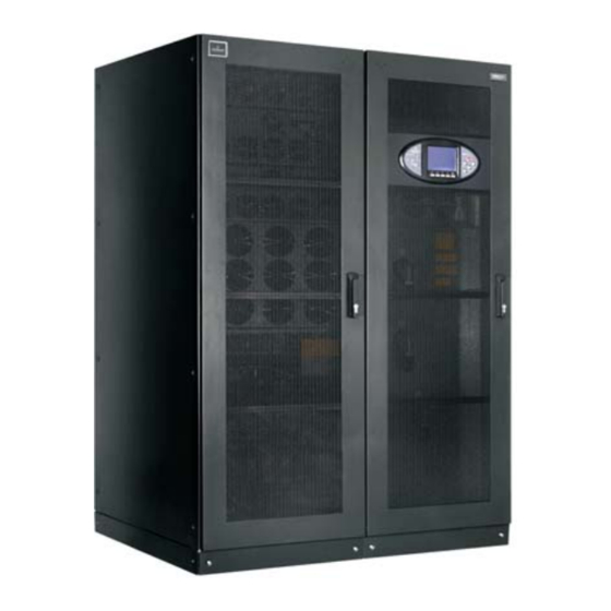
- Page 1 Liebert ® ™ User Manual – 250-800kVA UPS...
- Page 3 Revision date December 10, 2013 31012712 Emerson Network Power provides customers with technical support. Users may contact the nearest Emerson local sales office or service center. Copyright © 2012 by Emerson Network Power Co., Ltd. All rights reserved. The contents in this document are subject to change without notice.
- Page 5 near heat sources or strong electromagnetic interferences Disclaimer Emerson disclaims any and all responsibility or liability for the defection or malfunction caused by: application range or operating environment outside the specifications unauthorized modification, improper installation or operation ...
- Page 6 Safety Precaution This manual contains important instructions that should be followed during installation and operation of this Emerson NX Uninterruptible Power Supply (UPS for short). Read this manual thoroughly before installing, servicing and using the UPS. The UPS must be commissioned and serviced by trained engineers approved and qualified by the manufacturer or its agent.
- Page 7 Warning: multiple power inputs This UPS system receives power from more than one source . Disconnection of all AC sources and the DC source is required before servicing. This UPS has several circuits that are energized with high DC as well as AC voltages. Check for voltage with both AC and DC voltmeters before working within the UPS.
- Page 8 This Manual Describes The Following UPS Products Product Model 250kVA Liebert NX 0250kTK16FN01000 300kVA Liebert NX 0300kTK16FN01000 300kVA E Liebert NX 0300kTK16FN02000 400kVA Liebert NX 0400kTK16FN01000 500kVA Liebert NX 0500kTK16FN01000 600kVA E Liebert NX 0600kTK16FN02000 600kVA Liebert NX 0600kTK16FN01000 800kVA Liebert NX 0800kTK16FN01000...
-
Page 9: Table Of Contents
Contents Chapter 1 Overview ................................1 1.1 Features................................1 1.2 Design Concept ..............................1 1.2.1 System Design ............................1 1.2.2 Bypass............................... 2 1.2.3 System Control Principle ........................... 2 1.2.4 UPS Power Supply Switch Configuration ....................3 1.2.5 BCB ................................5 1.3 Parallel System .............................. - Page 10 3.1.5 Power Cable Connecting Terminal ......................18 3.1.6 Protective Earth ............................18 3.1.7 External Protective Device........................18 3.1.8 Power Cable Connection Procedures...................... 19 3.2 Wiring Of Signal Cable............................29 3.2.1 Overview..............................29 3.2.2 Input Dry Contact Port ..........................30 3.2.3 BCB Port..............................31 3.2.4 Output Dry Contact Port ..........................
- Page 11 5.5 Battery Capacity Test Procedures ........................57 5.6 System Test Procedures............................. 58 5.7 UPS Shutdown Procedures ..........................58 5.7.1 Completely Powering Down UPS ......................58 5.7.2 Completely Powering Down UPS Whilst Maintaining Power Supply To Load ......... 58 5.8 EPO Procedures ..............................59 5.9 UPS Reset Procedures............................
- Page 12 7.3.2 Procedures For Operating From Maintenance Bypass................74 7.3.3 Isolation Procedures (Of One UPS In A Parallel System) ............... 74 7.3.4 Insertion Procedures (Of One UPS In A Parallel System) ............... 74 7.3.5 Shutdown Procedures (Completely Powering Down UPS)..............74 7.3.6 Shutdown Procedures (Completely Powering Down UPS Whilst Maintaining Power Supply To Load)...
- Page 13 10.2.1 Magnetic Component: Transformer, Inductor ..................91 10.2.2 Power Semiconductor Component ......................91 10.2.3 Electrolytic Capacitor ..........................91 10.2.4 AC Capacitor ............................91 10.2.5 Service Life And Recommended Replacement Time Of Key Component ..........91 10.2.6 Fuse Replacement ..........................92 10.2.7 Replacement Of Air Filter ........................
-
Page 15: Chapter 1 Overview
Chapter 1 Overview Chapter 1 Overview This chapter introduces the features, design concept, parallel system, operation mode, battery management and battery protection of NX 250kVA ~ 800kVA UPS (hereinafter referred to as UPS). 1.1 Features The UPS is connected between the three-phase input power and the critical loads (e.g. computer) to provide high quality three-phase power for the loads. -
Page 16: Bypass
In this case, please contact the local customer service center of Emerson for technical support. (Parallel system) In the event of a fault in a unit, the unit will be automatically excluded from the system. If the system is still capable of providing the required load, the remaining units will continue to supply the load with no interruption. -
Page 17: Ups Power Supply Switch Configuration
Chapter 1 Overview Overload If the inverter is overloaded or the inverter current remains outside the specifications (refer to Table 11-6) longer than the specified time, the load will be automatically transferred to the bypass without power interruption. If both the overload and the current are reduced to a level within the specified range, then the load will be transferred back to the inverter. - Page 18 Chapter 1 Overview This mode supports two configurations: rectifier and bypass adopt two-route mains input, rectifier and bypass adopt one route input, but this mode does not support maintenance mode. Figure 1-3 describes the block diagram of the UPS in split bypass configuration (that is, the bypass adopts independent mains input).
-
Page 19: Bcb
Chapter 1 Overview Maintenance switch Q3 Bypass Static switch power supply Bypass switch Q2 Four switch option Four switches option Rectifier Inverter Static switch Mains input output DC bus Mains Output Main input switch Q1 switch Q5 Battery Figure 1-5 UPS power supply switch configuration (500kVA ~ 600kVA E with four switches) 600kVA~800kVA There are four switches: Q1, Q2, Q3, and Q5. -
Page 20: Parallel System Features
Chapter 1 Overview Moreover, two UPS module systems or parallel systems can comprise a dual bus system. Each UPS module or parallel system has independent output. Output synchronization is achieved through LBS, thus enabling seamless load transfer between the two systems. 1.3.1 Parallel System Features 1. - Page 21 Chapter 1 Overview Rectifier Inverter Mains input UPS output Main input switch Output switch Battery Battery charger Figure 1-7 Schematic diagram of normal mode Battery mode As shown in Figure 1-8, the UPS is operating in battery mode when the battery is supplying backup power to the load through the inverter.
-
Page 22: Battery Management
Chapter 1 Overview Parallel redundancy mode For higher capacity or higher reliability or both, the outputs of multiple UPS modules can be programmed for directly paralleling while a built-in parallel controller in each UPS ensures automatic load sharing. The parallel system can be composed of up to four UPS modules. - Page 23 Chapter 1 Overview The external battery connects to the UPS through the external BCB. The BCB is manually closed and tripped by the UPS control circuit. NX UPS Single Module And Parallel System 250kVA ~ 800kVA User Manual...
-
Page 24: Chapter 2 Mechanical Installation
2. Unpack the UPS, visually examine the UPS and check if there is any external or mechanical damage. If you spot any damage, seek assistance from the local customer service center of Emerson. 3. Verify the UPS label and confirm the correctness of the UPS. The UPS label is attached on the back of the door. -
Page 25: Battery Location Selection
Chapter 2 Mechanical Installation (such as metallic powder, sulfide, sulfur dioxide, graphite, carbon fiber, conductive fiber, and so on), acid mist or other conductive media (strongly ionized substances). The environment specifications should comply with relevant international standard & specifications and the operating range (see Table 11-2) specified in this manual. The UPS is air-cooled with the aid of internal fans. -
Page 26: Clearances
Chapter 2 Mechanical Installation Note Take special care when moving the battery cabinet fitted with batteries, in which case, the moving distance shall be minimized. The UPS can be moved by means of a fork lift or similar equipment. 2.4.3 Clearances As the UPS has no ventilation grills at either side, no clearances are required for either side. - Page 27 Chapter 2 Mechanical Installation Maintenance switch Q3 (optional) Main power cabinet 1 Main power cabinet 2 Bypass cabinet Bolt M10×30 (2 pcs) Plain washer M10 (4 pcs) 平 Spring washer M10 (2 pcs) Nut M10 (2 pcs) A amplified view A处放大图...
-
Page 28: Installation Diagram
Chapter 2 Mechanical Installation 2.5 Installation Diagram See Figure 2-2 to Figure 2-4 for key mechanical characteristics of the UPS. 924.4 1193.0 899.9 745.5 Main power cabinet Bypass cabinet Side view Front view 36.0 528.0 65.0 528.0 32.5 Main power Bypass cabinet cabinet Main power cabinet Bypass cabinet... - Page 29 Chapter 2 Mechanical Installation Front view Side view 1202 1903 Top view (door open) Bottom view Installation hole 8-13*20 1486 1524 1091 Figure 2-3 Top/front/side/bottom view of 500kVA ~ 600kVA E UPS (unit: mm) NX UPS Single Module And Parallel System 250kVA ~ 800kVA User Manual...
- Page 30 Chapter 2 Mechanical Installation 924.7 900.2 2386.0 Main power cabinet 1 Bypass cabinet Main power cabinet 2 646.2 745.3 Front view Side view Main power Main power Bypass cabinet cabinet 1 cabinet 2 Top view (door open) 68.5 70.0 68.5 36.0 528.0 525.5...
-
Page 31: Chapter 3 Electrical Installation
Chapter 3 Electrical Installation Chapter 3 Electrical Installation This chapter mainly introduces the electrical installation of the UPS, including the wiring of the power cables and signal cables. After completing the mechanical installation of the UPS, it is required to connect the power cables and control cables of the UPS. -
Page 32: Minimum Distance From Floor To Ups Connection Point
Chapter 3 Electrical Installation Rated current (A) Busbar stud size Main input, output Output current Max. battery Bypass input and Max. Max. battery and battery rating full load discharge output terminals input discharge terminals (kVA) current , current current (BAT N) Torque Torque (BAT+, BAT-) -
Page 33: Power Cable Connection Procedures
Important The operations described in this section must be performed by authorised personnel. If you have any questions, please contact the local customer service center of Emerson immediately. Connection terminal and cable routing method Figure 3-1 and Figure 3-3 show the UPS power cable connection terminals. Figure 3-4 ~ Figure 3-8 show the power cable entry and routing methods. - Page 34 Chapter 3 Electrical Installation BAT- BAT+ Switch Q1 is an option Switch extension bar (4 pcs) BAT N Bypass cabinet Main power cabinet mA2 mB2 mC2 oA oB oC oN/bN mA1 mB1 mC1 mN Note: 1. mA1, mB1, mC1, mA2, mB2, mC2, mN: rectifier input 2.
- Page 35 Chapter 3 Electrical Installation Output switch Q5 (option) PE copper bar PE1 (top cable entry) Switch extension bar (4 pcs) Maintenance switch Q3 (option) i/o/bN Bypass switch Q2 (option) Mains switch Q1 (option) PE2 (bottom cable entry) BAT- BAT+ Note: 1.
- Page 36 Chapter 3 Electrical Installation Switch extension bar (4 pcs) Maintenance switch Q3 (optional) mA mB i/o/bN BAT+ BAT- Note: 1. mA, mB, mC: rectifier input 2. bA, bB, bC: bypass input 3. BAT+, BAT-: battery input 4. oA, oB, oC: output 5.
- Page 37 Chapter 3 Electrical Installation Remove the cover here and lead the cables into the cabinet Route and bind the cables along the cable binding holes on the inside of the cabinet Connect the cables to the bypass terminals Connect the cables to the output terminals Bind the cables Bind the cables through the...
- Page 38 Chapter 3 Electrical Installation Connect the cables to the bypass terminals Connect the cables to the output terminals Bind the cables through the cable Bind the cables through the binding holes here cable binding holes here Remove the cover here, lead the cables into the main power cabinet and connect Remove the cover here and lead them to corresponding terminals...
- Page 39 Chapter 3 Electrical Installation Remove the cover here and lead the cables into the cabinet Connect the cables to the output terminals i/o/bN Connect the cables to the bypass terminals Connect the cables to the mains terminals Connect the cables to the battery input terminals Top cable entry Figure 3-6 5000kVA ~ 600kVA E UPS power cable routing method (top cable entry)
- Page 40 Chapter 3 Electrical Installation Connect the cables to the output terminals Connect the cables to the bypass terminals i/o/bN Connect the cables to the mains terminals Connect the cables to the battery input terminals Bind the cables through the cable binding holes here Remove the cover here and lead the cables into the cabinet...
- Page 41 Chapter 3 Electrical Installation In top cable entry, remove these covers, lead the cables into the cabinet and connect them to corresponding terminals Cable binding beam (top cable entry) Cable binding beam (bottom cable entry) In bottom cable entry, remove these covers, lead the cables into the cabinet and connect them to corresponding terminals Figure 3-8 600kVA ~ 800kVA UPS power cable entry method...
- Page 42 Chapter 3 Electrical Installation 3. Identify and make power connections for the input cables according to one of the following two procedures, depending on the type of installation. Common input connections 1) In common bypass and rectifier input configuration: 250kVA ~ 400kVA: Connect the AC input cables to the bypass input terminals (bA-bB-bC) in the bypass cabinet, connect the input neutral line to the bypass neutral terminal bN in the bypass cabinet Ensure correct phase rotation.
-
Page 43: Wiring Of Signal Cable
Chapter 3 Electrical Installation 4. Connect the system output cables between the output terminals (250kVA ~ 400kVA: oA-oB-oC-oN; 500kVA ~ 600kVA E: oA-oB-oC-i/o/b N; 600kVA ~ 800kVA: oA-oB-oC-i/o/b N) in the bypass cabinet and the critical load. Refer to Table 3-1 for the torque. Ensure correct phase rotation. Warning If the load will not be ready to accept power on the arrival of the commissioning engineer, ensure that the system output cables are safely isolated at their ends. -
Page 44: Input Dry Contact Port
Chapter 3 Electrical Installation Dry contact ports Intellislot 2 Intellislot 3 J15 J25 J19 J13 Intellislot 1 J17 J23 J28 J26 J34 J38 RS232 Note: J23 reserved Amplified view of dry contact ports Figure 3-10 Dry contact port and communication port (500kVA ~ 600kVA E) The UPS accepts external signalling from voltage-free (dry) contacts connected to push-in input dry contact terminal through the phoenix terminals on the bypass control module. -
Page 45: Bcb Port
Chapter 3 Electrical Installation 3.2.3 BCB Port Ports J15, J19, J20, J21, J29, J30, J31 and J32 are BCB ports. The ports are shown in Figure 3-12 and described in Table 3-4. J15 and J32, J19 and J31, J21 and J29, J20 and J30 constitute four groups of independent BCB ports respectively. -
Page 46: Remote Epo Input Port
Chapter 3 Electrical Installation 3.2.5 Remote EPO Input Port The UPS has an EPO function that operates by a button on the operator control and display panel of the UPS or by a remote contact provided by the user. The EPO switch is under a hinged plastic shield. J24 is the remote EPO input port. -
Page 47: Cable Entry And Routing
Chapter 3 Electrical Installation 3.2.7 Cable Entry And Routing Note After connection, take appropriate measures to seal the cable entry holes. 1. 250kVA ~ 400kVA UPS If using top cable entry method, remove the small cover on the top of the bypass cabinet, as shown in Figure 3-15, and lead the cables into the cabinet and connect them to corresponding ports. - Page 48 Chapter 3 Electrical Installation Step 2: Lead the cables through protective ring, and then into the cabinet Protective ring Step 1: Remove the cable trough cover here Dry contact port and communication port Step 3: Connect cables to corresponding ports Step 4: Replace the cable trough cover Top cable entry...
- Page 49 Chapter 3 Electrical Installation Step 1: Remove the cable trough cover here Dry contact port and communication port Step 2: Lead cables into Step 3: Connect cables to the cabinet corresponding ports Step 4: Replace the cable trough cover Bottom cable entry Figure 3-17 Signal cable entry and routing method (500kVA ~ 600kVA E, bottom cable entry) 3.
-
Page 50: Electrical Cabinet Connection (600Kva ~ 800Kva)
Chapter 3 Electrical Installation Small cover Dry contact port and communication port Step 3: Connect the cables to corresponding ports Step 4: Replace the cable trough cover Step 2: Remove the cable trough cover here and route the cables through the cable trough Step 1: Remove the small cover here and lead the cables into the cabinet Figure 3-18 Signal cable entry and routing method (600kVA ~ 800kVA) - Page 51 Chapter 3 Electrical Installation Main power Bypass Main power 2#X5 board 1#X5 board cabinet 1 cabinet cabinet 2 W005 W002 W006 W001 1250A Q2 W002 W005 W001 W006 1250A Q3 Control box of Control box of UHRW3S671X11 UHRW3S671X11 main power main power cabinet 1 cabinet 2...
- Page 52 Chapter 3 Electrical Installation Main power Bypass Main power cabinet 1 cabinet cabinet 2 1250A 1250A Control box of Control box of UHRW 3S671X11 UHRW 3S671X11 main power main power cabinet 2 cabinet 1 BAT+ BAT- BAT- BAT+ BAT- BAT+ 1250A 1250A Note: W60, W61, W62, W63 are optional cables connected in the cabinet...
- Page 53 Chapter 3 Electrical Installation Cabling route Figure 3-22 Cabling route of power cables between main power cabinet 2 and bypass cabinet Cabling route Figure 3-23 Cabling route of communication cables between cabinets NX UPS Single Module And Parallel System 250kVA ~ 800kVA User Manual...
-
Page 54: Chapter 4 Operator Control And Display Panel
Chapter 4 Operator Control And Display Panel Chapter 4 Operator Control And Display Panel This chapter expounds the functions and use of the components on the operator control and display panel of the UPS, provides LCD display information, including the LCD screen types, detailed menu messages, prompt windows and UPS alarm list. -
Page 55: Audible Alarm (Buzzer)
Chapter 4 Operator Control And Display Panel Indicator State Description Solid green Load on battery Flashing green Battery EOD pre-warning Battery indicator Battery abnormal (failed, absent or polarity reversed) or battery converter abnormal Solid red (failed, overcurrent or overtemperature) Battery and battery converter normal, battery charging Solid green Load on bypass Bypass indicator... -
Page 56: Lcd Screen Type
Chapter 4 Operator Control And Display Panel Providing 320 × 240 dot matrix graphic display, the user-friendly and menu-driven LCD allows you to easily browse through the input, output, load and battery parameters of the UPS, learn current UPS status and alarm information, perform functional setting and control operation. -
Page 57: Ups Help Screen & Flow Chart
Chapter 4 Operator Control And Display Panel The functions of the menu keys F1 ~ F4 and HELP for the current screen are shown by self-explanatory icons in the keypad window as appropriate. From any menu on the primary screen, pressing the F1 key returns to the OutPut menu. -
Page 58: Detailed Description Of Menu Items
Chapter 4 Operator Control And Display Panel 4.3 Detailed Description Of Menu Items The description that follows refers to the LCD primary screen shown in Figure 4-3. System information window The system information window displays the current time, UPS name, configuration and alarm silencing state. This window requires no user operation. -
Page 59: Prompt Window
Chapter 4 Operator Control And Display Panel Menu Item Explanation Display contrast Adjust the LCD contrast Four formats selectable: MM/DD/YYYY, DD/MM/YYYY, MM/DD/ YYYY, Date format set YYYY/MM/DD Date & time Set the date and time Comm1 baud rate Set the RS232 communication baud rate of the RS232 port and Intellislot 1 port Comm2 baud rate Set the RS232 communication baud rate of Intellislot 3 port Comm3 baud rate... -
Page 60: Alarm List
Chapter 4 Operator Control And Display Panel Prompt Meaning If you select battery maintenance test, the battery will discharge until the UPS Battery will be depleted, confirm or cancel shuts down. This prompt appears to require your confirmation. Cancelling the test will ends the test and transfers the UPS to normal mode System self test finished, everything is OK No action required... - Page 61 Chapter 4 Operator Control And Display Panel Alarm Explanation Monitor flash update Monitoring software being updated Bypass flash update Bypass software being updated FLASH operate fail Historical record not saved Batt. float charging Battery state (float charge mode) Batt. boost charging Battery state (boost charge mode) Battery discharging Battery state (discharge mode)
- Page 62 Chapter 4 Operator Control And Display Panel Alarm Explanation This alarm appears when the load arises above 105% of the nominal rating. The alarm automatically resets once the overload condition is removed. 1. Find out if this alarm is true by checking which phase has overload through the load (%) displayed Block overload on the LCD.
- Page 63 Chapter 4 Operator Control And Display Panel Alarm Explanation This alarm is triggered by an inverter software routine when the amplitude or frequency of bypass voltage exceeds the limit. The amplitude threshold is fixed for ±10% rating. This alarm automatically resets once the bypass voltage returns to normal.
- Page 64 Note: If the alarms are caused by the values set by the Emerson-authorized commissioning engineer using the configuration software, and the user need to change the setting values, please contact the local customer service center of Emerson NX UPS Single Module And Parallel System 250kVA ~ 800kVA User Manual...
-
Page 65: Chapter 5 Operating Instructions
Chapter 5 Operating Instructions Chapter 5 Operating Instructions This chapter provides the operating precautions and detailed operating procedures of the UPS. 5.1 Brief Introduction 5.1.1 Precautions Important The user can conduct relative operation only after the authorized engineer carries out the first power on and test. Warning: hazardous mains and/or battery voltage The components that can only be accessed by opening the protective cover with tools cannot be operated by the user. - Page 66 Chapter 5 Operating Instructions Bypass switch Q2 Maintenance switch Q3 Main input switch Q1 (option) Output switch Q5 Figure 5-1 UPS power switch (250kVA ~ 400kVA) NX UPS Single Module And Parallel System 250kVA ~ 800kVA User Manual...
- Page 67 Chapter 5 Operating Instructions Output switch Q5 (option) Maintenance switch Q3 (option) Bypass switch Q2 (option) Main input switch Q1 (option) Figure 5-2 UPS power switch (500kVA ~ 600kVA E) NX UPS Single Module And Parallel System 250kVA ~ 800kVA User Manual...
-
Page 68: Verifying Dip Switch Setting (600Kva ~ 800Kva)
Chapter 5 Operating Instructions Bypass switch Q2 Maintenance switch Q3 (optional) Output switch Q5 Main input switch Q1 Figure 5-3 UPS power switch (600kVA ~ 800kVA) 5.1.3 Verifying DIP Switch Setting (600kVA ~ 800kVA) Opening the front door of the main power cabinet reveals a 2-bit DIP switch, as shown in Figure 5-4. The DIP switch sets the communication address of the main power cabinet, and it has been set in factory. -
Page 69: Ups Start-Up Procedures
Chapter 5 Operating Instructions Amplified view of DIP switch Figure 5-4 DIP switch 5.2 UPS Start-Up Procedures Warning 1. These procedures result in mains voltage being applied to the UPS output terminals. 2. If any load equipment is connected to the UPS output terminals, check with the user that it is safe to apply power. If the load is not ready to receive power, ensure that it is safely isolated from the UPS output terminals. -
Page 70: Procedures For Transfer Between Operation Modes
Chapter 5 Operating Instructions 2. When the rectifier start process is finished and the rectifier indicator goes solid green, close the external BCB. 3. Press the INVERTER ON key. The inverter starts up, and the inverter indicator flashes in green color. When the inverter is ready, the UPS transfers from bypass to inverter, the bypass indicator turns off, the inverter indicator and output indicator turn on. -
Page 71: Transfer From Maintenance Mode To Normal Mode
Chapter 5 Operating Instructions 2. Open the front door of the UPS, and place the switch Q3 in ‘ON’ position. At this time, the load is powered by the maintenance bypass. Caution When the UPS is in maintenance mode, the load is not protected against abnormal mains supply. 5.3.5 Transfer From Maintenance Mode To Normal Mode The following procedures will transfer the UPS from maintenance mode to normal mode. -
Page 72: System Test Procedures
Chapter 5 Operating Instructions When the battery test is complete, the system updates the battery data and actual battery capacity needed for calculating the battery autonomy time. 4. Stop the battery test. During battery capacity test, you can select the Stop testing option on the Command menu to abort the test. 5.6 System Test Procedures System test is to test the LED indication on the operator control and display panel. -
Page 73: Epo Procedures
Note During the automatic restart process, manual startup is disabled. Automatic restart must be set by authorized commissioning engineer of Emerson through background software. 5.11 Selecting Language The LCD menu and data display is available in two languages: Chinese and English. -
Page 74: Changing Current Date And Time
Chapter 5 Operating Instructions 5. Press the F2 (ESC) key repeatedly to return to the OutPut menu. At this point, the LCD displays all characters in the selected language. 5.12 Changing Current Date And Time Use the following procedures to change the system date and time: 1. -
Page 75: Chapter 6 Battery
Chapter 6 Battery Chapter 6 Battery This chapter introduces the relevant information of the battery, including the battery safety, installation and maintenance information, battery protection function, BCB box, battery temperature sensor and battery ground fault detector. 6.1 Introduction The UPS battery string consists of batteries connected in series to provide rated DC input voltage for the UPS inverter. -
Page 76: Ups Battery
Chapter 6 Battery Warning: hazardous battery voltage present behind protective covers otherwise, electrolyte leakage, battery bulge, fire or explosion may be caused. 7) Do not directly connect any conductor between the positive and negative terminals of the battery. Remove finger rings, watches, necklaces, bracelets and other metal objects before operating the battery, and ensure that the tools (for example, wrench) are wrapped with insulating material. -
Page 77: Precautions For Installation Design
Chapter 6 Battery 6.4 Precautions For Installation Design Note Precautions for installation, use and maintenance of the battery are described iin the relevant battery manual provided by the battery manufacturer. The safety precautions described in this section include the important matters that must be considered during the installation design. -
Page 78: Battery Protection
Chapter 6 Battery Table 6-2 Number of batteries Parameter 380V/400V/415V Number of cells (standard) 240 pcs End of discharge voltage 1.67Vdc/Cell ~ 1.90Vdc/Cell Float charging voltage 2.2Vdc/Cell ~ 2.3Vdc/Cell 6.6 Battery Protection The battery is connected to the UPS through the BCB. The BCB can be manually closed and has the electronic tripping device controlled by the UPS control circuit. -
Page 79: Battery Room Design
Chapter 6 Battery 5. The bending radius of the cable shall be larger than 10D, where D is the outer diameter of the cable. 6. After cable connection, it is prohibited to pull the battery cables or the cable terminals. 7. - Page 80 Chapter 6 Battery The BCB provides the following functions: Short circuit protection and EOD protection. The BCB opens automatically when the battery voltage drops to the EOD voltage point Supporting the UPS EPO function. The BCB opens automatically when the EPO switch on the operator control and display panel of the UPS is pressed Table 6-3 provides the mechanical specifications of the BCB box.
- Page 81 Chapter 6 Battery Current transformer of battery ground fault detector Top plate Battery terminal (+) Battery terminal (-) Battery terminal (N) PCB of battery ground fault detector Earth bar UPS terminal (N) UPS terminal (+) UPS terminal (-) BCB control board Bottom plate Cable entry hole Figure 6-4 Internal structure of BCB box...
-
Page 82: Battery Temperature Sensor (Option)
6.11 Battery Ground Fault Detector (Option) Emerson provides an optional battery ground fault detector. It includes a current transformer and a PCB, which should be installed in the BCB box. The installation position of the PCB is shown in Figure 6-4. If the BCB box uses top cable entry, the current transformer should be installed on the inside of the top plate of the BCB box, as shown in Figure 6-4;... -
Page 83: Battery Maintenance
Chapter 6 Battery 6.12 Battery Maintenance For the battery maintenance and maintenance precautions, refer to IEEE-Std-1188-2005 and the relevant manuals provided by the battery manufacturer. Note 1. Periodically check the screws of the battery terminals for loose connection. If there is any loose screw, tighten it immediately. 2. -
Page 84: Chapter 7 Parallel System & Dual Bus System
Chapter 7 Parallel System & Dual Bus System Chapter 7 Parallel System & Dual Bus System This chapter introduces the installation and operating of the parallel system and the installation of the dual bus system. 7.1 Overview The system can comprise of up to four UPS modules of the same power rating and connected in parallel without the need for a centralized mains static bypass. -
Page 85: External Protective Device
Chapter 7 Parallel System & Dual Bus System Input distribution External bypass switch Mains input Mains input L1,L2,L3,N L1,L2,L3,N UPS 1 UPS 2 Rectifier Rectifier Static Static switch switch Charger Charger Inverter Inverter Battery 1 Battery 2 L1,L2,L3,N L1,L2,L3,N Q1EXT Q2EXT QUPS QBYP... -
Page 86: Remote Epo
Chapter 7 Parallel System & Dual Bus System Note You must use the shortest parallel cables to suit the application and must not coil excess. Meanwhile, separate the parallel cables from the power cables to prevent electrical interferences. UPS 1 UPS 3 UPS 2 UPS 4... -
Page 87: Operating Procedures Of Parallel System
Chapter 7 Parallel System & Dual Bus System 2. The open circuit voltage provided is 12Vdc, <10mA. 3. The external EPO device can be composed of another control system which can disconnect the UPS mains supply or the bypass input. 4. -
Page 88: Procedures For Operating From Maintenance Bypass
7.3.3 Isolation Procedures (Of One UPS In A Parallel System) Important These procedures shall only be carried out by service personnel of Emerson or under their guidance. The following procedures apply when one UPS module must be isolated from the parallel system for repair due to... -
Page 89: Installation Of Dual Bus System
Chapter 7 Parallel System & Dual Bus System Refer to 5.7.2 Completely Powering Down UPS Whilst Maintaining Power Supply To Load for the operating procedures. 7.4 Installation Of Dual Bus System 7.4.1 Cabinet Installation A dual bus system consists of two independent UPS systems, each containing one or more (maximally four) parallel UPS modules, as shown in Figure 7-6 and Figure 7-7. -
Page 90: External Protective Device
Chapter 7 Parallel System & Dual Bus System 7.4.2 External Protective Device Refer to 3.1.7 External Protective Device. 7.4.3 Power Cable The power cable wiring is similar to that of single module system. Refer to 3.1 Wiring Of Power Cable. The bypass and rectifier input sources must be referenced to the same neutral potential. -
Page 91: Chapter 8 Option
Chapter 8 Option Chapter 8 Option This chapter provides the UPS option list and introduces the functions and installation of the options. 8.1 Option List See Table 8-1 for option list. Table 8-1 Option list Option Model Part No. Remark 02354490 (250kVA~400kVA) 02357552... -
Page 92: Bypass Load Sharing Inductor
Chapter 8 Option Option Model Part No. Remark Four switches assembly (Q1, Installed in factory. Applicable to 02358887 Q2, Q3, Q5) 500kVA and 600kVA E UPSs Shorting copper bar assembly Installed in factory. Applicable to when there is no bypass load 02358889 500kVA and 600kVA E UPSs sharing inductor... - Page 93 Chapter 8 Option Figure 8-1 Installing bypass load sharing inductors of 250kVA ~ 400kVA UPS (rear view) 4) Connect the cables W60, W61 and W62 according to the cable labels. Connect the L1, L2 and L3 ends of the cables W60, W61 and W62 respectively to the upper terminals of the bypass load sharing inductors L1, L2 and L3;...
- Page 94 Chapter 8 Option Note This procedure will cause power interruption to the load. (1) Turn off the load. (2) Disconnect the mains input and battery from the UPS. (3) Open the switch upstream of the UPS bypass input. (4) Wait five minutes for the internal DC bus capacitors to discharge, until all indicators on the UPS display panel turn off. 2) Remove the two rear panels of the bypass cabinet, disconnect the cables W54, W55 and W56 in the bypass cabinet from the copper bars Q5-2, Q5-4 and Q5-6 of the output switch Q5, and retain the screws.
-
Page 95: Bcb Box
If you need to monitor the UPS through network, you may select the SIC card, which supports SNMP protocol. The SIC card is a network management card. It can make the UPS made by Emerson real network equipment. It can also be connected to the IRM series sensor to provide environment monitoring function. -
Page 96: Relay Card
Others Cable options Emerson provides three cable options to connect the DB25 connector of the relay card, to suit the user’s different requirements on the functions of the connector. Figure 8-4 ~ Figure 8-6 show the appearance and wiring principle of each cable. - Page 97 Chapter 8 Option DB25 male (pin-type) K0_NO K0_COM K0_NC K1_NO K1_COM K1_NC K2_NO K2_COM K2_NC K3_NO K3_COM K3_NC Figure 8-4 Appearance and wiring schematic of cable 1 (UFDRY21SL1) DB25 male (pin-type) X14J7A plug (pin-type) Figure 8-5 Appearance and wiring schematic of cable 2 (UFDRY21SL2) This end is labelled "UPS"...
- Page 98 Chapter 8 Option Note Some electronic components on the relay card are sensitive to static electricity. To prevent static electricity from damaging the relay card, do not touch its electronic components or circuits, also avoid their contact with live objects. Please hold the side edges of the relay card when moving or installing it.
-
Page 99: Modbus Card
Hipulse, Hipulse U), air-conditioner (CM+, DataMate3000, DME, Deluxe), and LTS series STS developed by Emerson. It can also perform centralized monitoring over various ambient signals, such as temperature, humidity, smoke and fog, water logging, infrared, through optional equipment developed by Emerson, like UPS ambient signal adapter. -
Page 100: Four Switches Assembly
Chapter 8 Option 8.2.16 Four Switches Assembly This assembly contains the connection copper bar, Q1, Q2, Q3 and Q5, and is optional for 500kVA ~ 600kVA E UPS. If the user selects the cabinet with four switches, then this assembly is a must. Note that this option is fitted in factory. 8.2.17 Shorting Copper Bar When There Is No Bypass Load Sharing Inductor This assembly contains the connection copper bar, and is optional for 500kVA ~ 600kVA E UPS. - Page 101 Chapter 8 Option 1. Fix the LBS adapter. The dimensions of the LBS adapter are shown in Figure 8-9. The LBS adapter can use horizontal installation (see Figure 8-10) or vertical installation (see Figure 8-11). 216mm 46mm 134mm Figure 8-9 Dimensions of LBS adapter Figure 8-10 Horizontal installation Figure 8-11 Vertical installation 2.
- Page 102 Chapter 8 Option 3) Connect the communication cable (up to 150m) to the COM2 port of each LBS adapter. 4) Place the switch of the LBS adapter connected to the NX UPS in the right position, and place the switch of the LBS adapter connected to the non-NX UPS in the left position.
-
Page 103: Chapter 9 Communication
9.1 SNMP Protocol Communication If you need to monitor the UPS through network, you may select the SIC card provided by Emerson. This card supports SNMP protocol. The SIC card is a network management card. It can make the UPS developed by Emerson have network communication capability. - Page 104 Chapter 9 Communication functions are realized through the following ports on the front panel of the control module on the top of the bypass cabinet. Input dry contact port Output dry contact port BCB port Remote EPO input port For the functions and detailed information of these ports, refer to 3.2.2 Input Dry Contact Port ~ 3.2.5 Remote EPO Input Port.
-
Page 105: Chapter 10 Service And Maintenance
Chapter 10 Service And Maintenance Chapter 10 Service And Maintenance UPS system (including battery) needs regular maintenance in the long-term operation. This chapter mainly elaborates the advice on service life, regular inspection and maintenance of UPS key components, as well as the maintenance of UPS and the optional parts .Effective maintenance of UPS systems can reduce the risk of UPS failure and enable longer use of UPS. -
Page 106: Fuse Replacement
Chapter 10 Service And Maintenance Table 10-1 Service life and recommended replacement time of key components Key component Estimated life Recommended replacement time Recommended inspection period AC Capacitor ≥7 years 5 ~ 6 years 6 months Electrolytic capacitor ≥7 years 5 ~ 6 years 1 year ≥7 years... - Page 107 Chapter 10 Service And Maintenance Fixing screw Fixing bar Fixing bar Air filter Figure 10-1 Replacing air filter (250kVA ~ 400kVA, 600kVA ~ 800kVA) For 500kVA ~ 600kVA E UPS, refer to Figure 10-2 for the air filter replacement procedures: 1.
-
Page 108: Chapter 11 Specifications
Chapter 11 Specifications Chapter 11 Specifications The chapter provides the UPS specifications. 11.1 Conformity And Standards The UPS has been designed to conform to the European and international standards listed in Table 11-1. Table 11-1 European and international standards Item Normative reference General safety requirements for UPS EN62040-1/IEC62040-1/AS62040-1... -
Page 109: Electrical Characteristics (Input Rectifier)
Chapter 11 Specifications 11.4 Electrical Characteristics (Input Rectifier) Table 11-4 Rectifier AC input (mains) Rated power (kVA) Item Unit 300 E 600 E Rated AC input voltage 380/400/415, 3-phase 4-wire (+ PE ) TN power distribution system Input voltage range 228 ~ 478 Frequency 50/60 (tolerance: 40 ~ 70) -
Page 110: Electrical Characteristics (Bypass Input)
Chapter 11 Specifications Rated power (kVA) Item Unit 300 E 600 E Steady state voltage ± 1 stability Transient voltage ± 5 response Total harmonic voltage < 2 (linear load), < 5 (non-linear load Synchronisation window Rated frequency ±5 Slew rate (max. change rate of synchronisation Hz/s 1;... -
Page 111: Appendix 1 Glossary
Appendix 1 Glossary Appendix 1 Glossary Alternating current Battery circuit breaker Cross sectional area Direct current Dual in-line package Digital signal processor Electromagnetic compatibility End-of-discharge Emergency power off IGBT Insulated gate bipolar transistor Liquid crystal display Load bus synchronizer Network management system Protective earth Pulse width modulation RCCB... - Page 112 Network Power service technicians. While every precaution has been taken to ensure the accuracy and completeness of this literature, Emerson Network Power assumes no responsibility and disclaims all liability for damages resulting from use of this information or for any errors or omissions.
Need help?
Do you have a question about the Liebert NX300 Series and is the answer not in the manual?
Questions and answers