Table of Contents
Advertisement
Quick Links
Advertisement
Table of Contents

Subscribe to Our Youtube Channel
Related Manuals for Connect Tech FreeForm/PCI-104


Summary of Contents for Connect Tech FreeForm/PCI-104
- Page 1 FreeForm/PCI-104 User Manual Connect Tech, Inc. 42 Arrow Road Guelph, Ontario Canada, N1K 1S6 Tel: 519-836-1291 800-426-8979 Fax: 519-836-4878 Email: sales@connecttech.com support@connecttech.com URL: http://www.connecttech.com CTIM-00040 Revision 0.02 September 19, 2008...
-
Page 2: Limited Lifetime Warranty
Connect Tech Inc. provides a Lifetime Warranty for all Connect Tech Inc. products. Should this product, in Connect Tech Inc.'s opinion, fail to be in good working order during the warranty period, Connect Tech Inc. will, at its option, repair or replace this product at no charge, provided that the product has not been subjected to abuse, misuse, accident, disaster or non Connect Tech Inc. -
Page 3: Customer Support Overview
Customer Support Overview If you experience difficulties after reading the manual and/or using the product, contact the Connect Tech reseller from which you purchased the product. In most cases the reseller can help you with product installation and difficulties. In the event that the reseller is unable to resolve your problem, our highly qualified support staff can assist you. -
Page 4: Table Of Contents
Connect Tech FreeForm/PCI-104 User Manual Table of Contents Limited Lifetime Warranty......................2 Copyright Notice ........................2 Trademark Acknowledgment ..................... 2 Customer Support Overview ...................... 3 Contact Information ......................3 Table of Contents ........................4 List of Tables..........................5 List of Figures ..........................5 Introduction .......................... -
Page 5: List Of Tables
Connect Tech FreeForm/PCI-104 User Manual List of Tables Table 1: FreeForm/PCI-104 Components .................. 8 Table 2: Slot Selection (RSW1) ....................10 Table 3: FPGA Configuration Settings (J1) ................10 Table 4: JTAG Programming Header Pinout (P2)..............11 Table 5: SPI Flash Programming Header Pinout (P3) .............. 11 Table 6: High-Speed serial Connector Pinout (P4) .............. -
Page 6: Introduction
Connect Tech FreeForm/PCI-104 User Manual Introduction Connect Tech’s FreeForm/PCI-104 features Xilinx’s Virtex-5 multi-platform FPGA offering users a flexible, reconfigurable computing platform that also takes advantage of the high bandwidth capabilities of the PCI bus while communicating with various I/O interfaces. -
Page 7: System Overview
Connect Tech FreeForm/PCI-104 User Manual System Overview The following conceptual block diagram provides a high level overview of the FreeForm/PCI-104 and illustrates the general interconnection between components and connectors. For the actual orientation and description of components refer to Figure 2 and Table 1 respectively. -
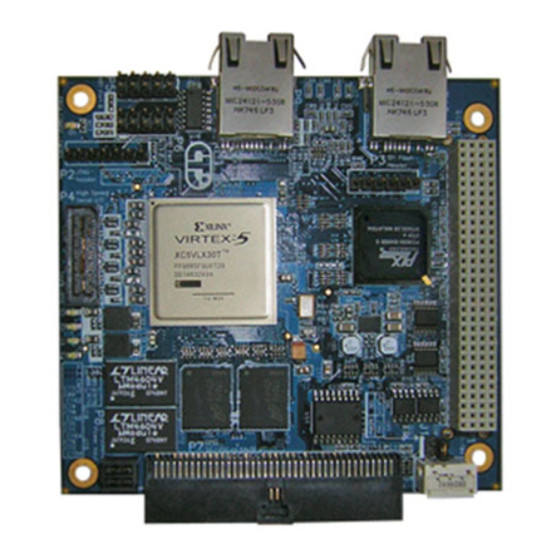
Page 8: Table 1: Freeform/Pci-104 Components
Connect Tech FreeForm/PCI-104 User Manual Figure 2: FreeForm/PCI-104 Layout Table 1: FreeForm/PCI-104 Components Connectors Description PCI-104 connector JTAG programming header SPI flash programming header High-speed serial connector P5, P6 RS-485 header GPIO header External power header RJ-45 A RJ-45 B... -
Page 9: Reference Design
Connect Tech FreeForm/PCI-104 User Manual Reference Design The FreeForm/PCI-104 ships with a pre-installed reference design that is loaded into the FPGA’s configuration flash. This reference design demonstrates how to interface the FreeForm/PCI-104 (Virtex-5 FPGA) with the PLX PCI 9056 PCI to Local Bus Bridge, as well as the various peripherals. -
Page 10: Hardware Description
Connect Tech FreeForm/PCI-104 User Manual Hardware Description The following sections describe the function of all switches/jumpers and provide details on connector pinouts. Jumpers and Switches Slot Selection (RSW1) This rotary switch selects a slot position in the PCI-104 stack. When mounting on a PCI adapter card, ensure slot one is selected. -
Page 11: Connector Pinouts
Connect Tech FreeForm/PCI-104 User Manual Connector Pinouts PCI-104 Header (P1) Refer to PCI-104 specifications. Note: P1 must be connected to a PCI-104 stack supplying both 3.3V and 5V. JTAG Programming Header (P2) Use P2 to configure the FPGA via JTAG. Refer to FPGA Configuration for more information. -
Page 12: High-Speed Serial (P4)
If connecting two FreeForm/PCI-104’s together using the Rocket I/O interface in a cross-over fashion; care must be taken. Ensure that only cables provided by Connect Tech are used. Cables ordered directly from Samtec or a third party could result in damage to the cable and/or the FreeForm/PCI-104 board itself. -
Page 13: Rs-485 Headers (P5, P6)
Connect Tech FreeForm/PCI-104 User Manual Top View RS-485 Headers (P5, P6) Table 7: RS-485 Port 1 Pinout (P5) Signal Direction RXD+1 Input RXD-1 Input TXD+1 Output 485 Port 0 TXD-1 Output Top View Power Table 8: RS-485 Port 2 Pinout (P6) -
Page 14: Gpio Header (P7)
Connect Tech FreeForm/PCI-104 User Manual GPIO Header (P7) When in differential mode, the GPIO header positive (P) and negative (N) signals are adjacent on a standard ribbon cable. Note that the GPIO voltage level is set via hardware. FCG001: L12 populated, enabling 2.5V I/O, including LVDS FCG002: L13 populated, enabling 3.3V I/O... -
Page 15: External Power Connector (P8)
VIO (connect to 5V) Power It is recommended that a Connect Tech Inc. FreeForm/PCI-104 power supply is used for providing external power. Orientation of the power supply connector is important. Ensure that the clip on the cable aligns with the catch on P8, as shown below. -
Page 16: Connector's Mating Components And Cables
Connect Tech FreeForm/PCI-104 User Manual Connector’s Mating Components and Cables The following table lists the manufacturer and part number for connectors on the FreeForm/PCI-104, as well as potential mating components. Table 11: Connector Mate Listing Connector Component on Mating components... -
Page 17: Hardware Installation
Each FreeForm/PCI-104 ships with a FPGA heat sink (27 mm x 27 mm); to be installed by the user. Simply peel of the sticker backing and press firmly onto the FPGA, using proper ESD precautions. If the heat sink size is not suitable for your application, please contact Connect Tech Inc. WARNING In many applications, including high speed memory operations, the FPGA dissipates a significant amount of power. -
Page 18: Software Installation
The reference design and example programs help users quickly develop custom hardware and software applications. Refer to the CD for installation instructions. The latest reference design is always available from: http://devel.connecttech.com/ If a username and password have not already been provided, please contact Connect Tech Support via email support@connecttech.com. Revision 0.02... -
Page 19: Fpga Configuration
Connect Tech FreeForm/PCI-104 User Manual FPGA Configuration The Virtex-5 FPGA can be configured via two methods: JTAG programming chain, using SPI Flash, read on, power-up by FPGA The configuration flash can be programmed (loaded) through three methods: JTAG programming chain (through FPGA), using... -
Page 20: Power And Thermal Considerations
PLLs, and high speed gigabit transceivers. The drawback of these on-chip features is that they consume a lot of power and hence dissipate a lot of heat. As a result Connect Tech, is recommending the installation of a heatsink, included with the product (see section Heat Sink Installation). -
Page 21: Specifications
Connect Tech FreeForm/PCI-104 User Manual Specifications Programmable FPGA Virtex-5 FPGA LX30T 100MHz Input Clock 128MB DDR2-400 Memory / Flash 2MB Flash – FPGA configuration 8MB Flash – Embedded code 4K serial EEPROM – parameter storage General Purpose User I/O 64 single ended I/O... -
Page 22: Appendix A: Impact Instructions For Fpga Configuration
Connect Tech FreeForm/PCI-104 User Manual Appendix A: iMPACT Instructions for FPGA Configuration To configure the FPGA via JTAG, connect the JTAG programming cable to ensuring that all JTAG signals align correctly. It is important to note that also has the TRST signal on pin 1, which is not part of Xilinx’s Parallel or USB programming cables. - Page 23 Connect Tech FreeForm/PCI-104 User Manual 3) A prompt will ask for a new configuration file. Select the bitstream from the project directory. 4) A prompt will ask for a BSDL file for device number 2 (PLX PCI9056). Click Yes. 5) Browse to the bsdl folder and select PCI9056BA.bsd...
- Page 24 Connect Tech FreeForm/PCI-104 User Manual 6) iMPACT will add the device to the JTAG chain. 7) Again, a prompt will ask for device number three (National PHY). Browse to the bsdl folder and select DP83849IVS.bsd. The device will be added to the JTAG chain.
-
Page 25: Programming The Fpga
Connect Tech FreeForm/PCI-104 User Manual Programming the FPGA 1) Right click on device number one (Virtex-5 FPGA), and select program. The following diagram will appear. Note that verification will only work if an msk file has been created. 2) Select OK to begin programming. After programming is complete, the status window will report:... -
Page 26: Generating A Prom (Mcs) File
Connect Tech FreeForm/PCI-104 User Manual Generating a PROM (MCS) File 1) Double click Prom File Formatter in the Flows window. 2) The “Prepare PROM Files” dialog will appear. Ensure that the following settings are selected: Party SPI PROM MSC PROM File Format 3) Give the file a name, and click Next. - Page 27 Connect Tech FreeForm/PCI-104 User Manual 4) Select the PROM density (16M) click Next click Finish. 5) A prompt will ask to add device to data stream 0. Click OK. Select the bitstream from the project directory. Revision 0.02...
- Page 28 Connect Tech FreeForm/PCI-104 User Manual 6) Click “No” when asked if another device is to be added. Click “OK” to accept the setup. 7) Double Click “Generate File” from the “iMPACT” processes menu. The status will be reported in the console.
-
Page 29: Configuring The Fpga With The Spi Flash
Connect Tech FreeForm/PCI-104 User Manual Configuring the FPGA with the SPI Flash In previous Xilinx FPGA configurations, the SPI flash required programming via 3 party JTAG test software or through in-system methods. The following features are new to ISE 9.1/9.2, and are only available on select FPGAs, including the Virtex-5. - Page 30 Connect Tech FreeForm/PCI-104 User Manual 3) Browse to the directory containing the previously generated MCS file. Select and click “Open”. 4) The “FPGA SPI Flash Association” window will appear; select “M25P16” (this is the flash device connected to the FPGA).
-
Page 31: Programming The Flash
Connect Tech FreeForm/PCI-104 User Manual Programming the Flash 1) Right click the previously associated flash device, and select program. 2) The programming dialog will appear. Select “Verify” and “Erase Before Programming”, then click “OK.” Revision 0.02... - Page 32 Connect Tech FreeForm/PCI-104 User Manual 3) Observe the results in the transcript window. The SPI core is first download to the FPGA device The IDCODE is checked and verified Flash is erased Flash is programmed After completion of the flash programming, the FPGA will attempt to configure itself from the flash.
-
Page 33: Appendix B: Power Calculations
Connect Tech FreeForm/PCI-104 User Manual Appendix B: Power calculations Scenario 1: Heatsink attached, 250 LFM Revision 0.02... -
Page 34: Scenario 2: No Heatsink, 250 Lfm
Connect Tech FreeForm/PCI-104 User Manual Scenario 2: No Heatsink, 250 LFM Revision 0.02... -
Page 35: Scenario 3: No Heatsink, 0 Lfm
Connect Tech FreeForm/PCI-104 User Manual Scenario 3: No heatsink, 0 LFM Revision 0.02... -
Page 36: Appendix C: Hardware Changes From Revision B
Connect Tech FreeForm/PCI-104 User Manual Appendix C: Hardware Changes from Revision B This appendix lists the changes between hardware revision B and hardware revision C. The following is a summary of changes: PCB requires only 5V over PCI-104; it previously required 3.3V and 5V A dedicated local bus oscillator was added to generate 50Mhz. -
Page 37: Reference Design
Connect Tech FreeForm/PCI-104 User Manual Reference Design The top level reference design contains a generic parameter which will correctly configure the FPGA for Revision B or Revision C. A separate constraint file UCF is created for Revision B and Revision C, which need to be added to the ISE project manually. -
Page 38: Hardware Description
Connect Tech FreeForm/PCI-104 User Manual Hardware Description Connector Pinouts High-speed Serial (P4) The sideband LVCMOS signals (HSS) have been rearranged so that when two FreeForm units are connected: HSS_USER_IO(0) maps to HSS_USER_IO(2) HSS_USER_IO(1) maps to HSS_USER_IO(3) Also, 3.3V pins replace the GND pins; this is because the connector has embedded GND blades. -
Page 39: Specifications
Connect Tech FreeForm/PCI-104 User Manual External Power Connector (P8) The connector no longer enables 3.3V regulation – it is always enabled. Revision B Revision C Signal Signal 3.3 enable (connect to 5V) VIO (connect to 5V) VIO (connect to 5V)
Need help?
Do you have a question about the FreeForm/PCI-104 and is the answer not in the manual?
Questions and answers