Table of Contents
Advertisement
WARNING
Improper installation, adjustment, alteration, service or
maintenance can cause property damage, injury or death,
and could cause exposure to substances which have been
determined by various state agencies to cause cancer, birth
defects or other reproductive harm. Read the installation,
operating and maintenance instructions thoroughly before
installing or servicing this equipment.
FOR YOUR SAFETY
The use and storage of gasoline or other flammable vapors
and liquids in open containers in the vicinity of this appliance
is hazardous.
CAUTION
To prevent premature heat exchanger failure do not locate
ANY gas-fired units in areas where chlorinated, halogenated
or acid vapors are present in the atmosphere.
INSTALLATION AND SERVICE MANUAL
All models approved for use in California by the CEC (when
equipped with IPI), in New York by the MEA division, and in
Massachusetts. Unit heater is certified for non-residential
applications.
Contents
Inspection on arrival . . . . . . . . . . . . . . . . . . . . . . . . . . . . . . 1
Installation . . . . . . . . . . . . . . . . . . . . . . . . . . . . . . . . . . . . . 2
Performance data . . . . . . . . . . . . . . . . . . . . . . . . . . . . . . . 10
Dimensional data . . . . . . . . . . . . . . . . . . . . . . . . . . . . . . . 11
Operation . . . . . . . . . . . . . . . . . . . . . . . . . . . . . . . . . . . . . 16
Checking input rate . . . . . . . . . . . . . . . . . . . . . . . . . . . . . . 16
Propeller heaters. . . . . . . . . . . . . . . . . . . . . . . . . . . . . . . . 19
Service instructions . . . . . . . . . . . . . . . . . . . . . . . . . . . . . . 21
Troubleshooting guide . . . . . . . . . . . . . . . . . . . . . . . . . . . . 22
Motor data . . . . . . . . . . . . . . . . . . . . . . . . . . . . . . . . . . . . 25
Control options . . . . . . . . . . . . . . . . . . . . . . . . . . . . . . . . . 26
Rating plate identification . . . . . . . . . . . . . . . . . . . . . . . . . 27
Warranty . . . . . . . . . . . . . . . . . . . . . . . . . . . . . . . Back cover
FOR YOUR SAFETY
If you smell gas:
1. Open windows
2. Don't touch electrical switches.
3. Extinguish any open flame.
4. Immediately call your gas supplier.
THIS MANUAL IS THE PROPERTY OF THE OWNER.
PLEASE BE SURE TO LEAVE IT WITH THE OWNER WHEN
YOU LEAVE THE JOB.
Inspection on Arrival
1.
Inspect unit upon arrival. In case of damage, report
immediately to transportation company and your local
Modine sales representative.
2.
Check rating plate on unit to verify that power supply meets
available electric power at the point of installation.
3.
Inspect unit received for conformance with description of
product ordered (including specifications where applicable).
6-558.6
P/N 5H72256A Rev. F
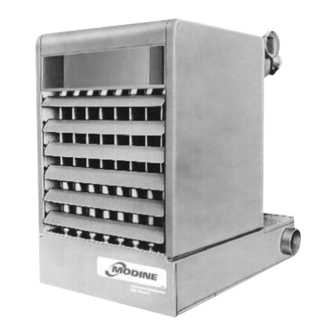
separated combustion
high efficiency
gas-fired unit heaters
models PSH & BSH
Heater Parts from ACF Greenhouses
October, 2002
Page
Advertisement
Table of Contents

Subscribe to Our Youtube Channel
Related Manuals for Modine Manufacturing PSH


Summary of Contents for Modine Manufacturing PSH
- Page 1 6-558.6 P/N 5H72256A Rev. F October, 2002 INSTALLATION AND SERVICE MANUAL separated combustion high efficiency gas-fired unit heaters models PSH & BSH All models approved for use in California by the CEC (when equipped with IPI), in New York by the MEA division, and in Massachusetts.
-
Page 2: Installation
8. To prevent premature failure do not located ANY gas-fired replacement parts list may be obtained by contacting unit heaters in areas where chlorinated, halogenated or Modine Manufacturing Company. Refer to the rating acid vapors are present in the atmosphere. plate on the unit for complete unit model number, serial number and company address. -
Page 3: Product Description
INSTALLATION Product Description Combustion Air Requirements Modine PSH and BSH model unit heaters are listed as separated Modine models PSH and BSH separated combustion units are combustion unit heaters and are defined as follows: A unit heater designed to receive air for combustion directly from the outside for installation in non-residential structures which, when connected atmosphere via field installed combustion air piping between the unit and the outside atmosphere. - Page 4 INSTALLATION Figure 2 4. Install the vent and combustion air pipes with a downward Suspension Methods slope from the appliance of 1/4 inch per foot and suspend securely from overhead structures at points no greater than 3 feet apart. Fasten individual lengths of vent together with at least three corrosion resistant sheet metal screws.
- Page 5 INSTALLATION Venting Instructions for Concentric Vent Figure 3 Options Adapter Box Assembly with Typical Field Supplied Mounting Brackets The concentric vent concept allows for the vent pipe and the combustion air pipe to pass through one hole in an EXTERIOR wall or roof. The concentric vent kits offered are horizontal or vertical.
- Page 6 INSTALLATION 8. Place this assembly (the adapter box, vent pipe and 1. The vent must terminate with a Gary Steel Model 1092 or combustion air pipe) through the wall or roof and verify that Briedert Type L cap for the appropriate pipe size. the distance requirements as defined in the following 2.
- Page 7 INSTALLATION Horizontal Two Pipe Venting Table 2 Gas Pipe Capacities Figure 9 In Cu. Ft. per Hour with Pressure Drop of 0.3 in W.C. with Specific Gravity 0.60. Horizontal Venting - Two Pipes Length Diameter of Pipe — Inches of Pipe in Ft.
- Page 8 INSTALLATION 6. Provide a drip pocket before each unit and in the line where The power to these units should be protected with a fused low spots cannot be avoided. (See Figure 7). disconnect. Units for use with three-phase electric power must be provided with a motor starter having properly sized overload 7.
-
Page 9: Performance Data
INSTALLATION Recommended Installations Dimension “B” Should Never Be Less than 1/2 of “A” TURNING 3" MAX. VANES 12" 3" MIN. MIN. 12" 3" MIN. MIN. 12" 3" MAX. TURNING VANES 12" MIN. BAFFLE SIDE VIEW SIDE VIEW TOP VIEW 12" 12"... - Page 10 OPERATION from the factory set performance. The drive number on the Figure 9a unit may be identified by referring to the Power Code Belt Tension Adjustment number on the serial plate of the unit (see page 23 for model number nomenclature) and matching that number with those shown on page 25.
-
Page 11: Checking Input Rate
Pilot Flame Adjustment CHECKING INPUT RATE Input Adjustments The pilot is orificed to burn properly with an inlet pressure of 6- 7" W.C. on natural gas and 11-14" W.C. on propane gas, but The gas pressure regulator (part of the combination gas final adjustment must be made after installation. - Page 12 CHECKING INPUT RATE Table 4 6. If pressure as indicated by “U” tube is less than 1/2" higher or lower than indicated in TAble 5, adjust regulator as Time for 1 Input, Cu. Ft. per Hour, When Meter Dial Size is: described under “meter-Timing method,”...
- Page 13 CHECKING INPUT RATE Table 5 Manifold Pressure & Gas Consumption Natural Propane Typical Heating Value (BTU/Cu.Ft.) 1040 2500 No. of Model Specific Gravity 0.60 1.53 Orifices Manifold Pressure inches w.c. 10.0 Cfh ........PSH130 Gal/Hr.
- Page 14 SEPARATED COMBUSTION PROPELLER UNIT HEATERS The minimum recommended installation clearance from top and rear of unit (motor) is six inches. Clearance to sides is eighteen inches, and clearance at bottom should equal “C” dimension shown in table for each model. DO NOT USE PROPELLER UNITS WITH DUCT WORK.
- Page 15 SEPARATED COMBUSTION BLOWER UNIT HEATERS The minimum recommended L = C + P (APPROX.) installation clearance from top and rear of unit (motor) is six inches. Clearance to sides is eighteen " inches, and clearance at bottom " should equal “C” dimension shown "...
- Page 16 PERFORMANCE DATA — BLOWER UNIT HEATERS Blower Models With or Without Blower Enclosures 0.0 Static Pressure 0.1 Static Pressure 0.2 Static Pressure 0.3 Static Pressure 0.4 Static Pressure Outlet Pulley Pulley Pulley Pulley Pulley Model Flow Velocity Temp. RPM Drive Turns RPM Drive Turns RPM Drive Turns RPM Drive Turns RPM...
- Page 17 Blower Models With Filter 0.0 Static Pressure 0.1 Static Pressure 0.2 Static Pressure 0.3 Static Pressure 0.4 Static Pressure Outlet Pulley Pulley Pulley Pulley Pulley Model Flow Velocity Temp. RPM Drive Turns RPM Drive Turns RPM Drive Turns RPM Drive Turns RPM Drive Turns Number CFM Rise F...
-
Page 18: Motor Data
MOTOR DATA Power Code Description — PSH Models Model PSH130 PSH150 PSH170 PSH225 PSH280 PSH340 Power Electric Code Power Horsepower 115/60/1 230/60/1 200/60/3 200/460/60/3 Motor Data and Total Unit Power Requirements — PSH Models Voltage 115/60/1 230/60/1 200-208/60/3 230/460/3 Motor Motor Total Total... -
Page 19: Motor Data
MOTOR DATA Blower Drive Numbers Motor Blower Sheave Motor Blower Sheave Sheave Sheave Min/Max Drive Belt No. Drive Belt No. Min/Max Pitch Dia. Bore Browning Browning Pitch Dia. Pitch Dia. Bore Bore Pitch Dia. Bore 0.750 1.9/2.9 0.500 1.000 1.9/2.9 0.625 0.750 1.9/2.9... -
Page 20: Performance Data
PERFORMANCE DATA 30°, 60° and 90° Downward Deflector Hoods - Propeller PSH Models Mounting 30° Height to Downward Bottom Deflector of Heater Hood Propeller Models (See Figures A and B) Model PSH 130 PSH 150 PSH 170 PSH 225 PSH 280 PSH 340 —... - Page 21 PERFORMANCE DATA 30°, 60° and 90° Downward Deflector Hoods - Propeller BSH Models Mounting 30° Height to Downward Bottom Deflector of Heater Hood Propeller Models (See Figures A and B) Model BSH 130 BSH 150 BSH 170 BSH 225 BSH 280 BSH 340 —...
- Page 22 PERFORMANCE DATA Nozzles - Performance A choice of four air discharge nozzles accommodate various heat throw patterns illustrated. Equipped with adjustable louver 90° Vertical Nozzle blades, nozzles are fabricated from galvanized steel and are offered either unpainted or painted to match the finish of the blower unit heaters.
-
Page 23: Dimensional Data
DIMENSIONAL DATA " " 40° Downward Nozzle 40° Splitter Nozzle " " 40° Vertical Nozzle 5-Way Nozzle Dimensions (in feet) Nozzle Dimension Model Number Type Symbol BSH 130 BSH 150 BSH 170 BSH 225 BSH 280 BSH 340 21-1/16 23-3/16 23-3/16 26-3/16 31-1/8... -
Page 24: Operation
SERVICE INSTRUCTIONS — SAFETY DEVICES Figure 13 Rear View Propeller Type Unit JUNCTION BOX PRESSURE SWITCH TERMINAL SENSING TUBES BOARD PRESSURE SWITCH MOTOR SIDE PANEL MOUNTING SCREWS SIGHT GLASS GAS SUPPLY CONNECTION ACCESS PANEL Limit Control (Overheat Switch) 5. On propeller units check fan speed against speed on motor nameplate. -
Page 25: Troubleshooting Guide
SERVICE INSTRUCTIONS — GENERAL Only people trained and familiar with the operation of unit c. Primary air shutters (when used). heaters and their controls should service this unit. d. Clean heat exchanger tubes from bottom with stiff brush after removing burner. (Do not use wire brush.) General Maintenance e. - Page 26 TROUBLESHOOTING GUIDE 2. Yellow Tipping. Yellow tipping of a normally blue flame is dust may be blocking the heat exchanger. Check and clear caused by insufficient primary air, and indicates incomplete any blockage. Adjust primary air to get rid of yellow tipping combustion producing carbon monoxide ethylene, aldehyde, that may produce soot to block heat exchanger.
-
Page 27: Rating Plate Identification
TROUBLESHOOTING GUIDE 2. Pilot lights, main burner will not light. 3. Burner shuts down before thermostat is satisfied. Possible Cause Possible Remedy Possible Cause Possible Remedy 2a. Gas valve in off 2a. Turn to on position. 3a. Flame sensing 3a. Check flame sensing rod, sensor off position. - Page 28 DELAY IN DELIVERY, OR ANY LOSS SUSTAINED BY THE BUYER. WITHIN ONE YEAR FROM DATE OF RESALE BY BUYER IN ANY Modine Manufacturing Company has a continuous product improvement program; it reserves the right to change design and specifications without notice.
Need help?
Do you have a question about the PSH and is the answer not in the manual?
Questions and answers