Table of Contents
Advertisement
WARNING
Improper installation, adjustment,
alteration, service or maintenance can cause
property damage, injury or death, and could
cause exposure to substances which have
been determined by various state agencies to
cause cancer, birth defects or other
reproductive harm. Read the installation,
operating and maintenance instructions
thoroughly before installing or servicing this
equipment.
CAUTION
To prevent premature heat exchanger failure
do not locate ANY gas-fired units in areas
where chlorinated, halogenated, or acid vapors
are present in the atmosphere.
PLEASE BE SURE TO LEAVE IT WITH THE OWNER WHEN YOU LEAVE THE JOB.
INSTALLATION AND SERVICE MANUAL
THIS MANUAL IS THE PROPERTY OF THE OWNER.
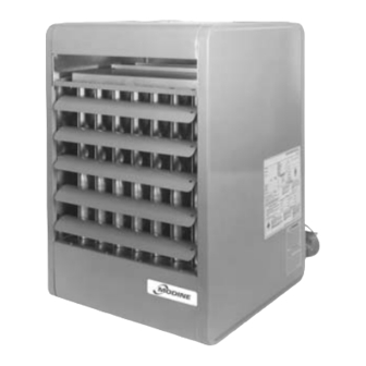
gas-fired unit heaters
models PD and BD
All models approved for use in California by the CEC (when
equipped with IPI), in New York by the MEA division, and in
Massachusetts. Unit heater is certified for non-residential
applications.
FOR YOUR SAFETY
If you smell gas:
1. Open windows.
2. Don't touch electrical switches.
3. Extinguish any open flame.
4. Immediately call your gas supplier.
FOR YOUR SAFETY
The use and storage of gasoline or other
flammable vapors and liquids in open containers
in the vicinity of this appliance is hazardous.
IMPORTANT
The use of this manual is specifically intended
for a qualified installation and service agency.
A qualified installation and service agency must
perform all installation and service of these
appliances.
Inspection on Arrival
1.
Inspect unit upon arrival. In case of damage, report
immediately to transportation company and your local
Modine sales representative.
2.
Check rating plate on unit to verify that power supply meets
available electric power at the point of installation.
3.
Inspect unit received for conformance with description of
product ordered (including specifications where applicable).
6-553.4
5H73889A Rev. E
July, 2003
Advertisement
Table of Contents

Related Manuals for Modine Manufacturing PD


Summary of Contents for Modine Manufacturing PD
-
Page 1: Inspection On Arrival
July, 2003 INSTALLATION AND SERVICE MANUAL gas-fired unit heaters models PD and BD All models approved for use in California by the CEC (when equipped with IPI), in New York by the MEA division, and in Massachusetts. Unit heater is certified for non-residential applications. -
Page 2: Table Of Contents
SAFE, EFFICIENT AND TROUBLE-FREE OPERATION. replacement parts list may be obtained by contacting IN ADDITION, PARTICULAR CARE MUST BE EXERCISED Modine Manufacturing Company. Refer to the rating plate REGARDING THE SPECIAL PRECAUTIONS LISTED BELOW. on the appliance for complete appliance model number, FAILURE TO PROPERLY ADDRESS THESE CRITICAL AREAS serial number, and company address. -
Page 3: Si (Metric) Conversion Factors
SI (METRIC) CONVERSION FACTORS / UNIT LOCATION 11. In aircraft hangars, keep the bottom of the unit at least 10 SI (METRIC) CONVERSION FACTORS feet from the highest surface of the wings or engine Table 3.1 enclosure of the the highest aircraft housed in the hangar and in accordance with the requirements of the enforcing To Convert Multiply By To Obtain... -
Page 4: Unit Lifting And Unit Mounting
UNIT LOCATION Sound and Vibration Levels Propeller sizes 30 through 300 units without deflector hoods that do not hang level after being installed, can be corrected in place. All standard mechanical equipment generates some sound and Simply remove both outer side panels (screws to remove are on vibration that may require attenuation. -
Page 5: Installation
Condensing gastight. Condensate must be drained. 4. Modine Manufacturing Company offers power exhausters as an accessory. Power exhausters not supplied by Modine 8. When the vent passes through a combustable wall or floor, Manufacturing Company are not permitted. - Page 6 ADDITIONAL VENTING REQUIREMENTS FOR CATEGORY II INSTALLATION UNITS Vent system must provide for drainage of condensate. At the low Table 6.1 point of the vent system, install a tee fitting with a connector and Minimum Height from Roof to attach flexible tubing, minimum 3/8 inch I.D., and run to a drain. Lowest Discharge Opening Tee fitting and associated condensate disposal system must be periodically cleaned.
-
Page 7: Gas Connections
INSTALLATION Gas Connections be considered. Avoid pipe sizes smaller than 1/2". Table 7.1 allows for a 0.3" W.C. pressure drop in the supply WARNING pressure from the building main to the unit. The inlet pressure to the unit must be 6-7" W.C. for natural gas and 11-14"... -
Page 8: Electrical Connections
INSTALLATION Electrical Connections WARNING 1. Disconnect power supply before making wiring connections to prevent electrical shock and equipment damage. 2. All appliances must be wired strictly in accordance with wiring diagram furnished with the appliance. Any wiring different from the wiring diagram could result in a hazard to persons and property. -
Page 9: Duct Installation
INSTALLATION Figure 9.1- Typical Duct & Airflow Installation Recommended Installations Dimension “B” Should Never Be Less than 1/2 of “A” 3" MAX. TURNING 12" VANES MIN. 3" MIN. 12" 3" MIN. MIN. 12" 3" MAX. TURNING VANES 12" MIN. BAFFLE TOP VIEW SIDE VIEW SIDE VIEW... -
Page 10: Blower Adjustment
INSTALLATION To Install adjustable motor sheave is supplied with these units. If blower fan speed changes are required, adjust motor sheave as 1. Remove and discard the motor tie down strap and the follows: shipping block beneath the belt tension adjusting screw (Not used on all models.) NOTE: Do not fire unit until blower adjustment has been made or unit may cycle on limit (overheat) control. -
Page 11: Start-Up Procedure
START-UP PROCEDURE pressure for either gas is 14" W.C. If inlet pressure exceeds 14" IMPORTANT W.C., a gas pressure regulator must be added upstream of the combination gas valve. 1. To prevent premature heat exchanger failure, observe 19. Open the field installed manual gas shut-off valve. heat exchanger tubes. -
Page 12: Main Burner Adjustment
START-UP PROCEDURE Figure 12.2 Figure 12.1 Typical Combination Gas Control Correct Pilot Flame 3/4" to 1" GAS CONTROL KNOB PRESSURE REGULATOR ADJUSTMENT SCREW (UNDER CAP SCREW) INLET PRESSURE TAP OUTLET PRESSURE OUTLET INLET PILOT TUBING CONNECTION PILOT ADJUSTMENT RESET BUTTON SCREW Main Burner Adjustment Burner Flame Adjustment... -
Page 13: Control Operating Sequence
2500 No. of ORIFICES SHUTTER Model Specific Gravity 0.60 1.53 Orifices Manifold Pressure In. W.C. 10.0 28.6 12.0 PD 30 Gal/Hr. Propane – Orifice Drill Size 47.6 20.0 PD 50 Gal/Hr. Propane – BD 50 Orifice Drill Size 71.4 30.0 PD 75 Gal/Hr. - Page 14 The main gas valve is opened completely and the main burner is lit to 100% full fire. Table 14.1 Propeller and Blower Unit Heaters – PD and BD Models Type of Control Service...
- Page 15 Figure 15.1 Factory Mounted Option Location All units include the standard (STD) features. The unit must be (2) Ignition controller - (OPT) reviewed to determine the optional (OPT) features that may have The ignition controller is factory installed on the back of the unit been supplied with the unit.
-
Page 16: Options
OPTIONS (5) Control Step Down Transformer - (STD) (8) Vent Pipe Connection - (STD) The control step down transformer is located in the electrical All gravity vented unit heaters are supplied with an oval vent pipe junction box. The transformer is used to step down the supply connection. -
Page 17: General Performance Data
GENERAL PERFORMANCE DATA Table 17.1 - Performance — Propeller Models Standard Model Number PD 30 PD 50 PD 75 PD 100 PD 125 PD 150 PD 175 PD 200 PD 250 PD 300 PD 350 PD 400 Btu/Hr. Input 30,000... - Page 18 GENERAL PERFORMANCE DATA Blower Models Models With or Without Blower Enclosure For 575V selections and footnotes, please see page 19. 0.0 Static Air Pressure 0.1 Static Air Pressure 0.2 Static Air Pressure 0.3 Static Air Pressure 0.4 Static Pressure Temp Sheave Sheave Sheave...
- Page 19 GENERAL PERFORMANCE DATA Blower Models Filters For blower units with enclosure and filter, add Models With or Without Blower Enclosure the following static pressures to the static Data for use with filters only pressure determined by the system designer for total external static pressure. 0.5 Static Air Pressure 0.6 Static Air Pressure 0.7 Static Air Pressure...
- Page 20 GENERAL PERFORMANCE DATA TABLE 20.1 Power Code Description — Blower Models BD50 BD75 BD100 BD125 BD150 BD175 BD200 BD250 BD300 BD350 BD400 Power Code Electric Power HP Drive HP Drive HP Drive HP Drive HP Drive HP Drive HP Drive HP Drive HP Drive HP Drive HP Drive 115/60/1 1/4 182 1/4 184 1/4 200 1/4 188 1/4 191 –...
- Page 21 GENERAL PERFORMANCE DATA TABLE 21.2 Blower Drive Numbers Blower Sheave Motor Sheave Blower Sheave Motor Sheave Blower Sheave Motor Sheave Drive Drive Drive Belt No. Pitch Max. Pitch Belt No. Pitch Max. Pitch Belt No. Pitch Max. Pitch Bore Bore Bore Bore Bore...
-
Page 22: Performance Data Options/Accessories
PERFORMANCE DATA – NOZZLES 90° VERTICAL NOZZLE 40° DOWNWARD NOZZLE 5-WAY NOZZLES 40° SPLITTER NOZZLE Mounting Height, Heat Throw, Heat Spread (in feet) Model Number Nozzle Type BD 50 BD 75 BD 100 BD 125 BD 150 BD 175 BD 200 BD 250 BD 300 BD 350 BD 400 Max. - Page 23 PERFORMANCE DATA – HOODS FOR PROPELLER MODELS Performance Data — 30°, 60° and 90° Downward Deflector Hoods Mounting Height to 30° Downward Hood For Propeller Units Bottom of Heater PD 50 PD 75 PD 100 PD 125 PD 150 PD 175 PD 200...
- Page 24 PERFORMANCE DATA – HOODS FOR BLOWER MODELS Performance Data — 30°, 60° and 90° Downward Deflector Hoods Mounting Height to 30° Downward Hood For Blower Units Bottom of Heater BD 50 BD 75 BD 100 BD 125 BD 150 BD 175 BD 200 BD 250 BD 300...
-
Page 25: Dimensions Unit
Diameter of round vent pipe to fit oval opening. PD 30 through PD 300 — 2 holes (and the level hanging adjustment feature). PD 350 through PD 400 — 4 holes. (Listed is the hole diameter and threads per inch to accept threaded rod). - Page 26 DIMENSIONAL DATA Blower Units - Model BD Figure 26.1 Dimensional Drawings 4-5/8'' J VENT PIPE BLOWER FILTER RACK ENCLOSURE M (APPROX.) (OPTIONAL) (OPTIONAL) D (OPENING) L (MIN. DISTANCE TO WALL) L (MIN. DISTANCE TO WALL) Table 26.1 Dimensions (inches) — BD Model Number Dimension Symbol...
-
Page 27: Maintenance
MAINTENANCE All heating equipment should be serviced before each heating season to Burner and Pilot Assembly Removal assure proper operations. The following items may be required to have To remove the burner more frequent service schedule based on the environment in which the unit Shut off gas and electric supply. -
Page 28: Service & Troubleshooting
When servicing or repairing this equipment, use only factory- which have been wet. Replace defective controller. approved service replacement parts. A complete replacement parts list may be obtained by contacting Modine Manufacturing Company. Refer to the rating plate on the appliance for IMPORTANT complete appliance model number, serial number, and company address. - Page 29 SERVICE & TROUBLESHOOTING Table 29.1 Troubleshooting Trouble Possible Cause Possible Remedy Pilot does not light Main gas is off. Open manual gas valve. Power supply is off. Turn on main power. Air in gas line. Purge gas line. Dirt in pilot orifice. Check for plugged pilot orifice and clean with compressed air if necessary.
- Page 30 SERVICE & TROUBLESHOOTING Trouble Possible Cause Possible Remedy Flashback Too much primary air Reduce primary air. Main pressure set too high. Adjust to maximum of 14” W.C. Orifice too large. Check orifice size with those listed on the serial plate. Insufficient primary air.
-
Page 31: Model Nomenclature/Serial Plate
Figure 31.1 - Serial Number Designations 01 12 101 10 97 150 A E M 01 30 Control Code MOTOR SUPPLIER CODE 30 - Complete Control Code 01 - Century PD - Propeller YEAR OF 05 - Universal descriptions are shown on MANUFACTURE Unit etc. - Page 32 DELAY IN DELIVERY, OR ANY LOSS SUSTAINED BY THE BUYER. WITHIN ONE YEAR FROM DATE OF RESALE BY BUYER IN ANY As Modine Manufacturing Company has a continuous product improvement program, it reserves the right to change design and specifications without notice.
Need help?
Do you have a question about the PD and is the answer not in the manual?
Questions and answers