Advertisement
Table of Contents
- 1 Table of Contents
- 2 Installation (Including Venting)
- 3 Operation
- 4 Checking Input Rate
- 5 Dimensional Data
- 6 Service Instructions - Safety Devices
- 7 Service Instructions – Safety Devices
- 8 Service Instructions - General
- 9 Troubleshooting Guide
- 10 Motor Data
- 11 Motor Data
- 12 Control Options
- Download this manual
WARNING
!
Improper installation, adjustment, alteration, service or
maintenance can cause property damage, injury or death, and
could cause exposure to substances which have been
determined by various state agencies to cause cancer, birth
defects or other reproductive harm. Read the installation,
operating and maintenance instructions throroughly before
installing or servicing this equipment.
FOR YOUR SAFETY
The use and storage of gasoline or other flammable vapors
and liquids in open containers in the vicinity of this appliance is
hazardous.
To prevent premature heat exchanger failure
do not locate ANY gas-fired units in areas
where chlorinated, halogenated or acid
vapors are present in the atmosphere.
INSTALLATION AND SERVICE MANUAL
G
All models approved for use in California by the CEC (when
equipped with IPI), in New York by the MEA division, and in
Massachusetts. Unit heater is certified for non-residential
applications.
Contents
Inspection on arrival . . . . . . . . . . . . . . . . . . . . . . . . . . . . . . . . .1
Installation (including venting) . . . . . . . . . . . . . . . . . . . . . . .2-8
Operation . . . . . . . . . . . . . . . . . . . . . . . . . . . . . . . . . . . . . .9-10
Checking input rate . . . . . . . . . . . . . . . . . . . . . . . . . . . . . . . .11
Dimensional data . . . . . . . . . . . . . . . . . . . . . . . . . . . . . .12 & 15
Performance data . . . . . . . . . . . . . . . . . . . . . . . .13, 14 & 16-19
Service instructions - safety devices . . . . . . . . . . . . . . . .20-21
Service instructions - general . . . . . . . . . . . . . . . . . . . . . . . .22
Motor data . . . . . . . . . . . . . . . . . . . . . . . . . . . . . . . . . . . . .25-26
Control options . . . . . . . . . . . . . . . . . . . . . . . . . . . . . . . . . . . .27
Model identification . . . . . . . . . . . . . . . . . . . . . . . . . . . . . . . .28
Warranty . . . . . . . . . . . . . . . . . . . . . . . . . . . . . . . . . .Back cover
FOR YOUR SAFETY
If you smell gas:
1. Open windows
2. Don't touch electrical switches.
3. Extinguish any open flame.
4. Immediately call your gas supplier.
THIS MANUAL IS THE PROPERTY OF THE OWNER.
PLEASE BE SURE TO LEAVE IT WITH THE OWNER
WHEN YOU LEAVE THE JOB.
Inspection on Arrival
1.
Inspect unit upon arrival. In case of damage, report
immediately to transportation company and your local
Modine sales representative.
2.
Check rating plate on unit to verify that power supply meets
available electric power at the point of installation.
3.
Inspect unit received for conformance with description of
product ordered (including specifications where applicable).
6-551.31
Part 5H70880A (Rev. AA)
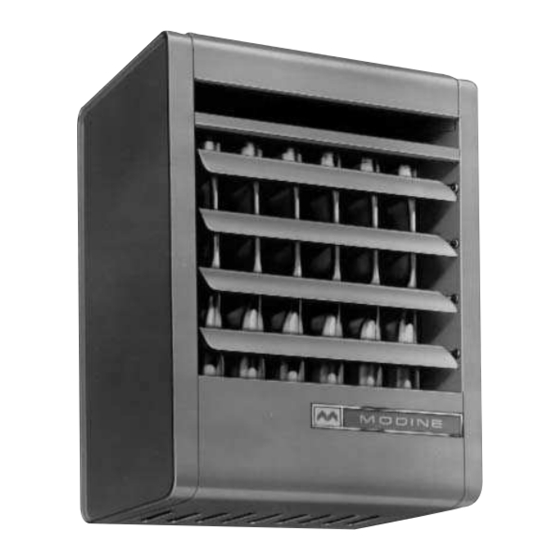
gas-fired unit heaters
models PAE and BAE
A
S
R
R
APPROVED
Heater Parts from ACF Greenhouses
July, 1996
Pages
Advertisement
Table of Contents

Related Manuals for Modine Manufacturing BAE


Summary of Contents for Modine Manufacturing BAE
-
Page 1: Table Of Contents
6-551.31 Part 5H70880A (Rev. AA) July, 1996 INSTALLATION AND SERVICE MANUAL gas-fired unit heaters models PAE and BAE APPROVED All models approved for use in California by the CEC (when equipped with IPI), in New York by the MEA division, and in Massachusetts. -
Page 2: Installation (Including Venting)
A complete replacement parts not be directed into the inlet of another. list may be obtained by contacting Modine Manufacturing Company. Refer to the rating plate on the unit for complete unit model number, 10. Do not locate units in tightly sealed rooms or small compartments serial number and company address. - Page 3 INSTALLATION In the U.S., the installation of these units must comply with the “National CAUTION Fuel Gas Code,” ANSI Z223.1, latest edition (also known as NFPA 54) and other applicable local building codes. For all sizes, minimum clearance to combustibles from the In Canada, the installation of these units must comply with local bottom is 12"...
-
Page 4: Venting Instructions
INSTALLATION CAUTION Table 1 PAE/BAE Venting System Category Gas Unit Heaters must be vented – do not operate unvented. Model Number Gas Controls Category A built-in draft hood (diverter) is provided – additional Single-Stage external draft hoods (diverters) are not required or PAE 30 Two-Stage permitted. - Page 5 INSTALLATION Piping Support piping so that no strains are imposed on unit or controls. CAUTION Use two wrenches when connecting piping to unit controls. Provide a sediment trap before each unit and in the line where low spots cannot be avoided. (See Figure 4). Gas pressure to unit heater controls must never exceed 14"...
- Page 6 INSTALLATION Wiring Attachment of Field Installed Ductwork, Blower dels (BAE) Models Only CAUTION CAUTION Disconnect power supply before making wiring connections to prevent electrical shock and equipment damage. ALL Do not attempt to attach ductwork of any kind to propeller UNITS MUST BE WIRED STRICTLY IN ACCORDANCE PAE models.
- Page 7 INSTALLATION Installation of Blower Models (BAE UNITS) To Install (Figure 5): 1. Remove and discard the motor tie down strap and the Determining Blower Speed shipping block beneath the belt tension adjusting screw (Not The drive assembly and motor on all gas-fired blower unit used on all models.) heaters are factory assembled.
- Page 8 INSTALLATION Blower Adjustments 5. To increase the speed of the blower, turn outer side of motor sheave clockwise. Following electrical connections, check blower rotation to assure 6. Retighten motor sheave set screw, replace belt and retighten blow-through heating. If necessary interchange wiring to reverse motor base.
-
Page 9: Operation
OPERATION Figure 7 CAUTION Correct Pilot Flame Pilot Flame Adjustment Start-up and adjustment procedures should be performed by a qualified serviceman. Check the gas inlet pressure at the unit upstream of the combination gas control. The inlet pressure should be 6"-7" W.C. - Page 10 OPERATION Lack of primary air will cause soft yellow-tipped flames. Excess where: primary air produces short, well-defined flames with a tendency F1 = input to heater, Btuh. to lift off the burner ports. Proper operation with natural gas F2 = input to heater, cu. ft. per hr. provides a soft blue flame with a well-defined inner core.
-
Page 11: Checking Input Rate
CHECKING INPUT RATE Table 4 Manifold Pressure & Gas Consumption * Figure 9 Natural Propane BTU/Cu. Ft. 1050 2500 No. of “U” TUBE Model Specific Gravity 0.60 1.53 Orifices ECO (ON UNITS MANOMETER Manifold Pressure In. W.C. 10.0 SO EQUIPPED. SEE NOTE 5 ON 28.6 12.0... - Page 12 DIMENSIONS/PERFORMANCE – PAE For all sizes, minimum clearance to com-bustibles from the bottom is 12 inches and from the sides 18 inches; for sizes 30-100 from the top is 1 inch and J VENT PIPE from the vent con-nector 2 inches; for sizes 125- 300 from the top is 2 inches and from the vent connector 3 inches;...
- Page 13 DIMENSIONS/PERFORMANCE – BAE For blower sizes, minimum clearance to combustibles from the bottom is 12", from the sides 4-5/8'' 18", and from the top and vent J VENT PIPE connector is 6". Allow at least 12" at the rear, or 6" beyond the end of the motor (whichever is greater), to provide ample air for combustion and for proper...
- Page 14 PERFORMANCE DATA – NOZZLES 90° VERTICAL A choice of four air discharge nozzles NOZZLE accommodate various heat throw patterns illustrated. Equipped with adjustable louver blades, nozzles are fabricated from galvanized steel and are offered either unpainted or painted to match the finish of the blower unit heaters.
-
Page 15: Dimensional Data
DIMENSIONAL DATA " " 40° 40° Downward Nozzles Splitter Nozzles " " 90° 5-Way Downward Nozzles Nozzle Dimensions (in inches) Model Number Nozzle Dimension Type Symbol BAE-50 BAE-75 BAE-100 BAE-125 BAE-145 BAE-175 BAE-200 BAE-225 BAE-250 BAE-300 BAE-350 BAE-400 14-13/16 16-13/16 18-9/16 18-9/16 21-1/16 23-3/16 23-3/16 26-3/16... - Page 16 PERFORMANCE DATA – HOODS Performance Data — 30°, 60° and 90° Downward Deflector Hoods — Propeller Models Mounting Height to 30° Downward Hood For Propeller Units Bottom of Heater Model PAE 50 PAE 75 PAE 100 PAE 125 PAE 145 PAE 175 PAE 200 PAE 225 PAE 250 PAE 300 PAE 350 PAE 400 X Y Z...
- Page 17 PERFORMANCE DATA – HOODS Performance Data — 30°, 60° and 90° Downward Deflector Hoods — Blower Models Mounting Height to 30° Downward Hood For Blower Units Bottom of Heater Model BAE 50 BAE 75 BAE 100 BAE 125 BAE 145 BAE 175 BAE 200 BAE 225 BAE 250 BAE 300 BAE 350 BAE 400...
- Page 18 PERFORMANCE DATA - BLOWER UNIT HEATERS Models With or Without Blower Enclosure 0.4 Static Pressure 0.0 Static Air Pressure 0.1 Static Air Pressure 0.2 Static Air Pressure 0.3 Static Air Pressure Sheave Temp Sheave Sheave Sheave Sheave Drive Turns Model Input Rise Airflow...
- Page 19 PERFORMANCE DATA - CONTINUED Models With or Without Blower Enclosure Data for use with filters only Filters 0.5 Static Air Pressure 0.6 Static Air Pressure Temp Sheave Sheave For blower units with enclosure and filter, add Model Rise Airflow RPM Drive Turns Drive Turns...
-
Page 20: Service Instructions - Safety Devices
SERVICE INSTRUCTIONS – SAFETY DEVICES Figure 13 Cross-section of Propeller Type Unit BLOCKED VENT ALUMINIZED STEEL SAFETY SWITCH DRAFT DIVERTER DIVERTER RELIEF OPENING VENT PIPE CONNECTION HEAT EXCHANGER DEFLECTOR BLADES FAN & FAN GUARD LIMIT CONTROL MAIN BURNER COMBUSTION AIR INLETS Limit Control (Overheat Switch) the left outer side panel, held in place by screws at the rear... -
Page 21: Service Instructions – Safety Devices
SERVICE INSTRUCTIONS – SAFETY DEVICES Limit Control (Overheat Switch) 2. Check actual input to unit against rated input. 3. Check to be sure motor is operating. The limit control, mounted on the left inner side panel (when facing front of unit), will shut off the gas supply to the main 4. -
Page 22: Service Instructions - General
SERVICE INSTRUCTIONS – GENERAL ONLY PEOPLE TRAINED AND FAMILIAR WITH THE Primary air shutters (when used). OPERATION OF UNIT HEATERS AND THEIR CONTROLS d. Clean heat exchanger tubes from bottom with stiff brush SHOULD SERVICE THIS UNIT. after removing burner (Do not use wire brush). General Maintenance Bottom pan. -
Page 23: Troubleshooting Guide
TROUBLESHOOTING GUIDE 2. Yellow Tipping 6. Flame Rollout Yellow tipping of a normally blue flame is caused by insufficient Flames rolling out of the combustion air inlets when the burner primary air, and indicated incomplete combustion producing is turned on can create a fire hazard, scorch unit finish, burn carbon monoxide, aldehydes, and free carbon (soot). - Page 24 TROUBLESHOOTING GUIDE 3. Effect of pilot operation on safety controls: 2. Pilot lights, main burner will not light POSSIBLE CAUSE POSSIBLE REMEDY POSSIBLE CAUSES AND REMEDIES 3a. A short pilot flame may cause poor ignition and result in 2a. Gas valve in off position. 2a.
-
Page 25: Motor Data
MOTOR DATA Power Code Description — Propeller PAE Models Pwr. Electric PAE 30 PAE 50 PAE 75 PAE 100 PAE 125 PAE 145 PAE 175 PAE 200 PAE 225 PAE 250 PAE 300 PAE 350 PAE 400 Code Power Horsepower 115/60/1 1/40 1/40... -
Page 26: Motor Data
MOTOR DATA Motor Data and Total Unit Power Requirements – Blower BAE Models Voltage 115/60/1 230/60/1 200/60/3 230/460/60/3 Mtr. Mtr. Total Total Mtr. Mtr. Total Total Mtr. Mtr. Total Total Mtr. Mtr. Total Total Amps Amps Watts Amps Rpm Amps Watts Amps Rpm Amps Watts Amps Amps Watts 1725... -
Page 27: Control Options
CONTROL OPTIONS Propeller and Blower Unit Heaters – PAE and BAE Models Control Type of Thermostat Service Voltage Control System Description Code No. Voltage Single-Stage, Standing Pilot, 100% Shut-Off – Utilizes a single-stage combination gas control and 115V natural thermocouple. Pilot needs to be manually lit initially and stays lit. 200/230V natural 115V... - Page 28 For service contact your local qualified installation and service contractor or appropriate utility company. Heating Division Modine Manufacturing Company 1221 Magnolia Avenue Buena Vista, VA 24416 Telephone: 540-261-2166 Fax: 540-261-1563 © Modine Manufacturing Company 1996 6/96 - 30M Litho in USA Heater Parts from ACF Greenhouses...
Need help?
Do you have a question about the BAE and is the answer not in the manual?
Questions and answers