
Related Manuals for Hanna Instruments HI 23 Series


Summary of Contents for Hanna Instruments HI 23 Series
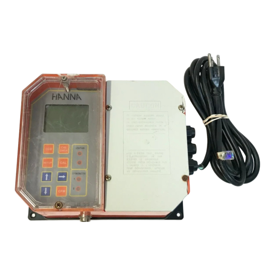
- Page 1 HI 23 / HI 24 Series Wall-mounted, Microprocessor-based, Conductivity and TDS Process Controllers Instruction Manual...
- Page 2 Dear Customer, Thank you for choosing a Hanna Product. This instruction manual refers to the following products: HI 23211-α α α α α EC controller with dual setpoint, ON/OFF control and analog output HI 23212-α α α α α EC controller with dual setpoint, ON/OFF control and RS 485 port HI 23221-α...
-
Page 3: Table Of Contents
EC / TDS PROBE MAINTENANCE ........55 ACCESSORIES .............. 56 WARRANTY ..............58 CE DECLARATION OF CONFORMITY ......59 © 2001 Hanna Instruments All rights are reserved. Reproduction in whole or in part is prohibited without the written consent of the copyright owner. -
Page 4: Preliminary Examination
PRELIMINARY EXAMINATION Remove the instrument from the packing material and exam- ine it carefully to make sure that no damage has occurred during shipping. If there is any noticeable damage, notify your Dealer or the nearest Hanna Customer Service Center immediately. -
Page 5: Main Features Of Different Models
MAIN FEATURES OF DIFFERENT MODELS • Display: large LCD with 4 ½ 13 mm digits and 3 ½ 7.7 mm digits. • LEDs: four LEDs are provided for signaling the energizing of relays 1 and 2 (yellow LEDs) and alarm relay (a green and a red LED). - Page 6 • Calibration and Setup procedures allowed only through an unlock password. • Calibration: 2 points with Hanna EC and TDS calibration solutions. • Four different EC working ranges (0 to 199.9µS; 0 to 1999µS; 0 to 19.99mS; 0 to 199.9mS). •...
-
Page 7: Functional Description
FUNCTIONAL DESCRIPTION 1. Liquid Crystal Display 2. CAL DATA key last calibration data viewing (enters and exits) 3. LCD key exits from setup and reverts back to normal mode (in idle or control phases with the measurement on the display). During EC/TDS calibration, it alternates EC/TDS buffer value and current cell constant on the display. - Page 8 1. RS 485 communications terminal (HI 23xy2 and HI 24xy2 models only) 2. Analog Output terminal (HI 23xy1 and HI 24xy1 models only) 3. Pt 100 Temperature Sensor terminal 4. Power supply output for external transmitter 5. 4-20 mA input from external transmitter 6.
-
Page 9: Mechanical Dimensions
MECHANICAL DIMENSIONS... -
Page 10: Specifications
SPECIFICATIONS Range 0.0 to 199.9 µS/cm, 0 to 1999 µS/cm 0.00 to 19.99 mS/cm, 0.0 to 199.9 mS/cm 0.0 to 100.0 ppm, 0 to 1000 ppm (HI 24 series only)* * * * * 0.00 to 10.00 ppt, 0.0 to 100.0 ppt (HI 24 series only)* * * * * -10.0 to 100.0 °C Resolution 0.1 µS/cm, 1 µS/cm, 0.01 mS/cm, 0.1 mS/cm... -
Page 11: Installation
INSTALLATION HI 23 and HI 24 series offer a multitude of possibilities, from dual setpoints to ON/OFF or PID dosage, isolated out- puts with user-selectable zoom, recorder outputs in mA and volts. Use the 3-wire Pt 100 temperature sensor to compensate for the cable resistance and have a precise automatic tempera- ture compensation of the measurements in long distance applications. - Page 12 • • • • • P P P P P ower Supply: ower Supply: ower Supply: ower Supply: ower Supply: Connect a 3-wire power cable to the terminal strip, while paying attention to the correct line (L), earth (PE) and neutral (N) terminal connections. Power: 230VAC - 50 mA.
- Page 13 If the Pt 100 has more than 2 wires, con- nect the two wires of one end to pins 9 and 10 (pin 9 is an auxiliary input to compensate for the cable resistance) and one wire from the other end to pin 8. Leave the fourth wire unconnected, if present.
-
Page 14: Setup Mode
Connect the two signal wires from the transmitter to terminals #5 on page 8, paying attention to the correct polarity. Termi- nal 14 is the positive input and terminal 15 is the negative input. An unregulated 10 ÷ 30 VDC - 50 mA max. power supply output (#4 on page 8) is pro- vided to power the transmitter, if needed. - Page 15 The setup codes can be selected after password and CFM are pressed. When CFM is pressed, the current setup item is saved on EEPROM and the following item is displayed. Whenever LCD is pressed, the device reverts back to control mode. The same is true when CFM is pressed on the last setup item.
- Page 16 Note The default password is set at “0000”. • The LCD will display “SET” on the up- per part and “c.00” on the lower, al- lowing the user to edit setup param- eters (see table below). • Using the arrow keys as for the above password proce- dure, enter the code of the parameter to set, e.g.
- Page 17 SETUP CODES The following table lists the setup codes along with the descrip- tion of the specific setup items, their valid values and whether password is required to view that item (“PW” column): Code Valid Values Default 00 Factory ID 0 to 9999 0000 01 Process ID...
- Page 18 Code Valid Values Default 21 Relay 2 mode (M2) same as relay 1 22 Relay 2 setpoint (S2) 0.5 to 99.5% full scale 75% f.s. 23 Relay 2 hysteresis (H2) 0 to 5% f.s. 1% f.s. 24 Relay 2 deviation (D2) 0.5 to 10% f.s.
- Page 19 Code Valid Values Default 71 Baud rate 1200, 2400, 4800, 9600 4800 72 Cleaning timer 0 to 19999 days 73 Initial cleaning day 01 to 31 74 Initial cleaning month 01 to 12 75 Initial cleaning year 1998 to 9999 1998 76 Initial cleaning time 00:00 to 23:59...
- Page 20 If M2= 1 then S2-H2 LA; If M2= 2 then S2+H2 HA; If M2= 3 then S2+D2 HA; If M2= 4 then S2-D2 LA; If M1= 1 and M2 = 2 then S1-H1 S2+H2, S2 LA, HA S1; If M1 = 2 and M2 = 1 then S2-H2 S1+H1, S1 LA, HA S2;...
-
Page 21: Control Mode
In the HI 24 series it is possible to switch between EC and TDS reading pressing “LCD”. The TDS value is obtained mul- tiplying the EC measurement by the TDS factor set through setup. The HI 23 series displays EC only. The status of the meter is shown by the LEDs. STATUS... - Page 22 An upper boundary is imposed for dosage time when relays are energized continuously, i.e. when relay works in ON/ OFF mode or also in PID mode but in the latter case only if the relay is always ON. This parameter can be set through the setup procedure.
- Page 23 de-energized when the EC value is above the setpoint plus the hysteresis. Setpoint Setpoint + Hysteresis The low setpoint relay may be used to control a low conduc- tivity dosing pump. P .I.D. CONTROL MODE (HI 23x2z and HI 24x2z models only) PID control is designed to eliminate the cycling associated with ON/OFF control in a rapid and steady way by means of the combination of the proportional, integral and de-...
- Page 24 The derivative function (rate action) compensates for rapid changes in the system reducing undershoot and overshoot of the EC or TDS value. During PID control, the ON interval is dependent not only on the error amplitude but even on the previous measurements. Definitely PID control provides more accurate and stable control than ON/OFF controllers and it is best suitable in system with fast response, quickly reacting to changes due...
- Page 25 second is the integrative action and the third is the deriva- tive action. Proportional action can be set by means of the Proportional Band (PB). Proportional Band is expressed in percentage of the input range and is related to Kp according to the follow- ing: 100% Controller...
- Page 26 The user can vary five different parameters, i.e. the setpoint (S1 or S2), the deviation (D1 or D2), the reset time, the rate time and the proportional control mode period T (from 1 to 30 minutes). Note User can disable the derivative and/or integrative action (for P or PI controllers) by setting Td = 0 and/or Ti = MAX (Ti) respectively through the setup procedure.
- Page 27 4. The deviation, Ti and Td can be calculated from the following: • Deviation = Tx * max. slope (EC/TDS) • Ti = Tx / 0.4 (minutes) • Td = Tx * 0.4 (minutes). 5. Set the above parameters and restart the system with the controller in the loop.
- Page 28 Moreover the alarm signal is generated only after a user se- lectable time period (alarm mask) has elapsed since the controlled value has overtaken one alarm threshold. This additional feature will avoid fake or temporary alarm con- ditions. Note If the power supply is interrupted, the relay is de-energized as if in alarm condition to alert the operator.
-
Page 29: Idle Mode
Note In order to have the Fail Safe feature activated, an external power supply has to be connected to the alarm device. CONTROL THROUGH ANALOG OUTPUT Models HI 23xy1 and HI 24xy1 have a proportional ana- log output signal (selectable among 0-1mA, 0-20mA, 4-20mA, 0-5VDC, 1-5VDC and 0-10VDC) at the analog output terminals. -
Page 30: Analog Output
Control actions are stopped as soon as the user presses SETUP and enters the pass- word. In order to reactivate the control mode, use code 02 of setup (see “Setup” section). Oth- erwise, the meter remains in idle mode. ANALOG OUTPUT Models HI 23xy1 and HI 24xy1 are provided with the ana- log output feature. - Page 31 The type (voltage or current) and the range of the output analog signal is selectable through the jumpers on the board. Analog output options are as follows: 0-5 VDC; 1-5 VDC 0-10 VDC (default) 0-20 mA; 4-20 mA (default) 0-1 mA Choice between different ranges with the same configura- tion (for example 0-20 mA and 4-20 mA) is achieved via software by entering the setup mode and selecting code 40...
-
Page 32: Calibration
CALIBRATION The controller is factory calibrated for temperature as well as for the analog input and outputs. The user should periodically calibrate the instrument for EC or TDS. For greatest accuracy, it is recommended that the instrument is calibrated frequently. Before beginning normal operation, it is recommended to standardize the probe with the Hanna calibration solution close to the expected sample value and inside the selected... - Page 33 To obtain accurate readings, use the calibration solution in the selected range and closer to the values to be mea- sured. Offset Calibration • To perform the EC or TDS calibration en- ter the calibration mode, by pressing CAL and entering the password. •...
- Page 34 • When the reading is stable, "CAL" will stop flashing (after about 30 seconds) and "CFM" indicator will blink. • Press CFM to confirm the calibration point; if the reading is close to the selected solu- tion, the meter stores the reading. If the reading is not close to the selected solution, "ERROR"...
- Page 35 CELL CONSTANT DIRECT SELECTION Whenever the EC/TDS probe cell constant is known, it is possible to directly calibrate the meter using that value. • Press CAL to enter calibration mode. The LCD will show 0. • Press LCD to display the current cell constant on the pri- mary LCD (factory default value is 2.000 cm •...
- Page 36 Note Press SETUP before CFM to exit without changes. Note It is suggested to calibrate the offset before entering the cali- bration buffer direct selection. TEMPERATURE CALIBRATION The controller is factory calibrated for temperature. However, the user may also perform a one point temperature calibra- tion.
- Page 37 Calibration procedure may be interrupted by pressing CAL again at any time. If the calibration procedure is stopped this way, or if the controller is switched off before the last step, no calibration data is stored in nonvolatile memory (EE- PROM).
- Page 38 • Press CFM to confirm. The meter will return to normal op- erational mode. Calibration procedure may be interrupted by pressing CAL again at any time. If the calibration procedure is stopped this way, or if the controller is switched off before the last step, no calibration data is stored in nonvolatile memory (EE- PROM).
- Page 39 OUTPUT OUTPUT OUTPUT OUTPUT OUTPUT CALIBRATION CALIBRATION CALIBRATION CALIBRATION CALIBRATION CALIBRATION CALIBRATION CALIBRATION CALIBRATION CALIBRATION CALIBRATION CALIBRATION CALIBRATION CALIBRATION CALIBRATION TYPE TYPE TYPE TYPE TYPE CODE CODE CODE CODE CODE POINT 1 POINT 1 POINT 1 POINT 1 POINT 1 POINT 2 POINT 2 POINT 2...
-
Page 40: Last Calibration Data
Note When adjusting values using the keys it is important to allow for sufficient response time (up to 30 seconds) The table below lists the values of output codes along with the calibration point values (which are the analog output minimum and the analog output maximum) as indicated on the display. -
Page 41: Fault Conditions And Selftest Procedures
• Press to cycle through the data forward or backwards respectively. Note In any moment, by pressing LCD or CAL DATA the meter will return to the regular operating display. • Press to view the time of last calibration. The sec- ondary display will show "HOU". - Page 42 A I2C failure is detected when the I2C transmission is not acknowledged or a bus fault occurs for more than a certain number of attempts (this can be due, for example, to dam- age sustained by one of the ICs connected to I2C bus). If so, the controller stops any tasks and displays a perpetual sliding message “Serial bus error”...
- Page 43 As soon as one or more keys are pressed, the appropriate segments out of 88:88 corresponding to the pressed keys, will light up on the screen. The correspondence is given below: For example, if UP and CAL are pressed together the LCD will look like this: The colon is a useful indicator for the correct position squares.
- Page 44 EEPROM SELFTEST The EEPROM selftest procedure involves verifying the stored EEPROM checksum. If the checksum is correct the “Stored data good” message will be shown for a few seconds be- fore exiting selftest procedure. If not, the message “Stored data error - Press to reset stored data or to ignore”.
-
Page 45: External Functions
WATCHDOG When a dead loop condition is detected a reset is automati- cally invoked. The effectiveness of watchdog capability can be tested through one of the special setup items. This test consists of executing a dummy dead loop that causes watchdog reset signal to be generated. -
Page 46: Rs 485 Communication
RS 485 COMMUNICATION HI 23xy2 and HI 24xy2 are provided with an RS485 port. RS485 standard is a digital transmission method that allows long lines connections. Its differential transmission system makes this standard suitable for data transmission in noisy environments. SPECIFICATIONS The RS485 standard is implemented in EC process meter controllers with the following characteristics:... - Page 47 Up to 32 units can be connected to the same RS485 line, with a total line length of up to 1.2 Km using 24AWG cable. To minimize electromagnetic interference, use shielded or twisted pair cable to connect the units. Each EC controller unit is identified by its process ID number (setup item “01”).
- Page 48 • Using the arrow keys, set the controller address. To exit setup, press CFM key and then LCD key. In an RS 485 network, each device must have a different Note address. • Select the desired baud rate with the up and down keys and press the CFM key to store the new settings.
- Page 49 null Same as LCD key null Same as key null Same as key null Same as SETUP key null Same as key null Request firmware code null Request EC reading (available in control or idle mode only) null Request TDS reading (available in control or idle mode only, for HI 24 series only)
- Page 50 “01SET33+015••<CR>” “01SET33+015••<CR>” “01SET33+015••<CR>” “01SET33+015••<CR>” “01SET33+015••<CR>” This command sets the setup item 33 (max. relay ON time) of a controller, identified by the process ID number 01, to 15 minutes. The • • • • • character means blank. Once the controller has received a command, it answers with its 2-digit process ID number followed by: •...
- Page 51 The time-out for the first character of the controller answer is 100 milliseconds. The minim delay between the last received character and first character of the answer is 15 ms. When the controller answers to the ECR, TDR and TMR com- mands, the reading is sent as ASCII string followed by a character indicating the control and alarm status of the controller and info for controller setup modified.
- Page 52 “03<STX>10.7D<ETX>” “03<STX>10.7D<ETX>” “03<STX>10.7D<ETX>” “03<STX>10.7D<ETX>” “03<STX>10.7D<ETX>” meaning that the current temperature reading is 10.7°C, the control action is active and no alarm condition is present and controller setup is modified (must update controller setup for PC – GET commands for setup items). If asking for the last calibration data and the controller was never calibrated, it answers with “0”;...
-
Page 53: Startup
STARTUP During the automatic startup the Real Time Clock (RTC) is checked to see if a reset occurred since last software initial- ization. In this case, the RTC is initialized with the default date and time 01/01/1998 - 00:00. An EEPROM reset does not affect the RTC settings. -
Page 54: Ec Values At Various Temperatures
EC VALUES AT VARIOUS TEMPERATURES Temperature has a significant effect on conductivity. Table below shows EC values at various temperatures for the Hanna calibration solutions. TEMPERATURE EC VALUES (µS/cm) °C °F HI7030 HI7031 HI7033 HI7034 HI7035 HI7039 HI8030 HI8031 HI8033 HI8034 HI8035 HI8039 7150 48300... -
Page 55: Ec / Tds Probe Maintenance
EC / TDS PROBE MAINTENANCE Probe can be compensated for normal contamination by a process of recalibration. When calibration can no longer be achieved, remove the conductivity probe from the sys- tem for maintenance. PERIODIC MAINTENANCE Inspect the probe and the cable. The cable used for the connection to the controller must be intact and there must be no points of broken insulation on the cable. -
Page 56: Accessories
ACCESSORIES CONDUCTIVITY CALIBRATION SOLUTIONS HI 7030L 12880 µS/cm solution, 500 mL bottle HI 7030M 12880 µS/cm solution, 230 mL bottle HI 7031L 1413 µS/cm solution, 500 mL bottle HI 7031M 1413 µS/cm solution, 230 mL bottle HI 7033L 84 µS/cm solution, 500 mL bottle HI 7033M 84 µS/cm solution, 230 mL bottle HI 7034L... - Page 57 OTHER ACCESSORIES HI 3011D 4-ring EC/TDS probe with standard 1/2’’ external thread for flow-thru mounting, DIN connector and 3 m (10’) cable HI 3012D 4-ring EC/TDS probe with standard 1/2’’ external thread for submersion applications, DIN connector and 3 m (10’) cable HI 7610 Stainless steel Pt100 probe with standard 1/2’’...
-
Page 58: Warranty
If the repair is not covered by the warranty, you will be notified of the charges incurred. If the instrument is to be returned to Hanna Instruments, first obtain a Returned Goods Authorization number from the Customer Service department and then send it with shipping costs prepaid. -
Page 59: Ce Declaration Of Conformity
CE DECLARATION OF CONFORMITY Recommendations for Users Before using these products, make sure that they are entirely suitable for the environment in which they are used. Operation of these instruments in residential areas could cause unaccept- able interferences to radio and TV equipment. To maintain the EMC performance of equipment, the recommended cables noted in the user's manual must be used. - Page 60 TECHNICAL SERVICE CONTACTS Australia: Tel. (03) 9769.0666 • Fax (03) 9769.0699 China: Tel. (10) 88570068 • Fax (10) 88570060 Egypt: Tel. & Fax (02) 2758.683 Germany: Tel. (07851) 9129-0 • Fax (07851) 9129-99 Greece: Tel. (210) 823.5192 • Fax (210) 884.0210 Indonesia: Tel.
Need help?
Do you have a question about the HI 23 Series and is the answer not in the manual?
Questions and answers