Table of Contents
Advertisement
Quick Links
Advertisement
Table of Contents

Related Manuals for TYAN Transport GT14 B2933


Summary of Contents for TYAN Transport GT14 B2933
- Page 1 Transport GT14 B2933 Service Engineer’s Manual...
- Page 3 TYAN retains the right to make changes to product descriptions and/or specifications at any time, without notice. In no event will TYAN be held liable for any direct or indirect, incidental or consequential damage, loss of use, loss of data or other malady resulting from errors or inaccuracies of information contained in this document.
- Page 4 Federal Communications Commission (FCC) Notice for the USA Compliance Information State- ment (Declaration of Conformity Procedure) DoC FCC Part 15: This device complies with part 15 of the FCC Rules Operation is subject to the following conditions: 1) This device may not cause harmful interference, and 2) This device must accept any interference received including inter- ference that may cause undesired operation.
- Page 5 About this Manual This manual provides you with instructions on installing your Transport GT14. This manual is intended for experienced users and integrators with hardware knowledge of personal computers. This manual consists of the following parts Chapter 1: Provides an Introduction to the Transport GT14 B2933 barebones, packing list, describes the external components, gives a table of key compo- nents, and provides block diagrams of the system.
- Page 6 SAFETY INFORMATION Before installing and using the Transport GT14, take note of the fol- lowing precautions: – Read all instructions carefully. – Do not place the unit on an unstable surface, cart, or stand. – Do not block the slots and opening on the unit, which are pro- vided for ventilation.
-
Page 7: Table Of Contents
Table of Contents Chapter 1:Overview 1.1 About the Transport GT14 B2933 ......1 1.2 Product Model......... 1 1.3 Features . - Page 8 2.7.1 Key Definition ........57 2.7.2 DOS Mode and Windows Mode ....58 2.7.3 Linux Mode .
-
Page 9: Chapter 1:Overview
Chapter 1: Overview About the Transport GT14 B2933 Congratulations on your purchase of the TYAN Transport GT14 B2933, a highly-optimized rack-mountable barebone system. The Transport GT14 B2933 is designed to support ® up to 2 AMD Athlon™ F Opteron™ 2000 1207-pin proces- sors, providing a rich feature set and incredible performance. -
Page 10: Features
• Stacked two (2) USB 2.0 ports Motherboard • One (1) 9-pin COM port • TYAN S2933G2NR • One (1) 15-pin VGA port • 10.4x9.4 inch (265mmx240mm) for • Two (2) LAN ports GT14 1U chassis • 8 layers PCB... - Page 11 • Operating temperature 5 C~35 • Port 80 code display LED • Non-operating temperature -40 Server Management • TYAN M3291, IPMI 2.0 (2x25pin) Remote system Mgmt card • Renesas H8S2167 BMC controller • BT, KCS, Logging support • IPMI-over-LAN • Remote power on/off •...
-
Page 12: Unpacking
If any items are missing or appear damaged, contact your retailer or browse to TYAN’s Web site for service: http://www.tyan.com. The Web site also provides information on other TYAN prod- ucts, plus FAQs, compatibility lists, BIOS settings, and more. Power Cables... - Page 13 Rail Kit Rail kit options: A, B, C The following three rail kits are available to rackmount your GT14 B2933. A. Rail for 4-post rack Sliding Rails x2 Sliding Brackets x4 (Front L-Bracket x2, Rear L-Bracket x2) Mounting Brackets x 4 M4-4L screw x 18pcs M5-8L screw x 10pcs M5-15L screw x 4pcs...
- Page 14 C. Rail for 4-post rack Inner Rails x2 Post Slide Mounting Brackets x4 Assembled Outer Sliding Rails x2 M4-4L screw x 30pcs M5-8L screw x 10pcs M5-15L screw x 4pcs NOTE: For detailed information on rail kit of C, please contact our sales representative.
-
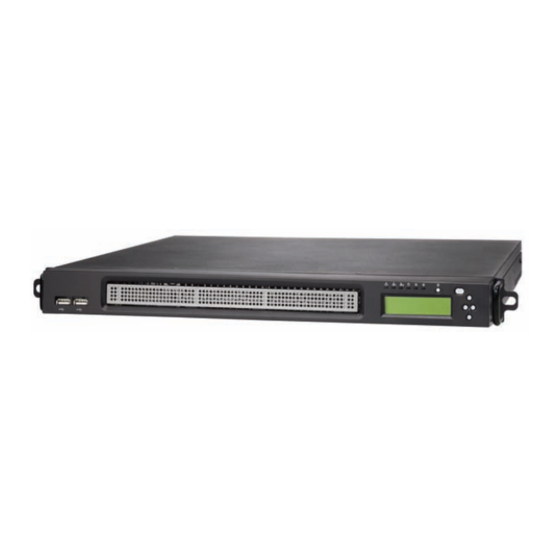
Page 15: About The Product
About the Product The following views show you the product. 1.5.1 Front View HDD Access LED LAN2 LED LAN1 LED ID LED Power LED Warning LED Power button LCD buttons ID button LCD Display 2 x USB ports 1.5.2 Rear View Power Supply Socket Power Supply Fan PCI-E Card... -
Page 16: Led Definition
1.5.3 LED Definition Front Panel Color State Description Power Green Power ON Power OFF HDD Access Amber Random Blink HDD access No disk activity LAN1/LAN2 Activity Green LAN linked Green Blinking LAN accessing No LAN linked Warning System fails (fan fail/ over voltage) Normal ID LED... -
Page 17: Internal View
1.5.4 Internal View FAN1 FAN2 FAN3 FAN4 1. M2083 PCI-E Riser card 6. Fans (Left to Right: Fan1, Fan2, Fan3, Fan4) 2. Memory slots 7. Front LED panel 3. EPS Power supply 8. 3.5” Hard disk drive bracket 4. Power connector 9. -
Page 18: Motherboard Block Diagram
1.5.5 Motherboard Block Diagram LINK 1 LINK 0 SATA4 SATA3 SATA2 SATA1 LINK RGMII BUS RGMII BUS Chapter 1: Overview... -
Page 19: Motherboard Layout
1.5.6 Motherboard Layout Chapter 1: Overview... - Page 20 Jumpers & Connectors Jumper Function /Connector J14~J21 4-pin Fan Connectors with Speed Control J21: FAN1, J20: FAN2, J19: FAN3, J18: FAN4 J17: FAN5, J16: FAN6, J15: FAN7, J14: FAN8 Front Panel Header SMDC Connector Barebone FAN Tachometer Pin Header Front Panel USB2.0 Connector LCM Connector Onboard ID LED Enable/Disable Jumper Close Pin 1 &...
-
Page 21: Fru List
1.5.7 FRU List Model Item Picture Quantity Description Number Standard Parts Dual 1207-pin ZIF sockets. Supports Motherboard S2933G2NR up to 2 AMD® F Opteron™ 2000 series processors. Chassis Unit; for Chassis Unit CCHA-0220 GT14 B2933 TF-Delta DPS- Power Supply CPUS-0280 400BBA;... - Page 22 Model Item Picture Quantity Description Number Mounting Ear Mounting Ear Kit, CEAR-0120 for GT14 TF-TYAN Front Panel Control Board Cable HS 2X14P/ CCBL-0340 HS 2X14P, L=250mm (Flat Cable) TF-USB Cable USB 2.0 Cable 2*5P K10P P2.54/2*5P CCBL-035A K10P P2.54, L=200mm, GT14...
- Page 23 Model Item Picture Quantity Description Number Optional Parts GT14 Standard Rail CRAL-0110 Kit; Rail for 4-post GT14 Open Rail Kit; Rack Mount- CRBK-0030 Rail for 2-post ing Part GT14 Dual Rail Kit; CRAL-0111 Rail for 4-post with 2 barebones TF-Cable Assy; Power SATA Cable CCBL-046D B4P(F)/ SATA(M)*2,...
- Page 24 Model Item Picture Quantity Description Number 2.5” Single TF-2_5_HDD_BKT CHDT-0111 HDD Bracket _ASSY; GT14 Chapter 1: Overview...
-
Page 25: Chapter 2:Setting Up
Chapter 2: Setting Up 2.0.1 Before You Begin This chapter explains how to install the CPU, CPU heatsink, memory modules, and hard drives. Instructions on inserting a PCI-E card are also given. Take note of the precautions mentioned in this section when installing your system. -
Page 26: Precautions
2.0.4 Precautions Components and electronic circuit boards can be damaged by discharges of static electricity. Working on a system that is connected to a power supply can be extremely dangerous. Follow the guidelines below to avoid damage to the Transport GT14 or injury to yourself. •... -
Page 27: Installing Motherboard Components
Installing Motherboard Components This section describes how to install components on to the motherboard, including CPU, memory modules and a PCI-E card. 2.1.1 Removing the Top Chassis Cover Follow these instructions to remove the Transport GT14 top chassis cover. 1. Remove the screw on the back side and two on the top of the top chassis cover. -
Page 28: Installing The Cpu And Heatsink
2.1.2 Installing the CPU and Heatsink Follow these instructions to install the CPU and CPU heatsink. 1. Locate the CPU sockets. 2. Remove the CPU socket cover. 3. Pull the CPU lever up to unlock the CPU socket (A). Then open the socket in the direction as shown (B). - Page 29 4. Place the CPU on the CPU socket, ensur- ing that pin 1 is located in the right direction. 5. Close the CPU socket cover (A) and press the CPU socket lever down to secure the CPU (B). 6. Place the air duct with heatsink on the top of the CPUs and attach with four screws as shown.
-
Page 30: Installing The Memory
2.1.3 Installing the Memory Follow these instructions to install the memory modules on the motherboard. 1. Locate the memory slots on the motherboard. 2. Press the memory slot locking levers in the direction of the arrows as shown in the following illustration. Chapter 2: Setting Up... - Page 31 3. Align the memory module with the slot. The module has indentations that align with notches in the slots. 4. Insert the memory module into the slot as shown. When inserted properly, the memory slot locking levers lock automatically onto the indentations at the ends of the module. 5.
- Page 32 Refer to the following tables for supported DDR2 populations. (Note: X indicates a populated DIMM slot.) DDR2 DIMM population is always from back to front (black slot first). DIMM slot 64bit-support P1_DIMM1 P1_DIMM3 P2_DIMM1 P2_DIMM3 ❈ Population order for 64-bit mode is DIMM3 first, then DIMM1. DIMM slot 128bit-support P1_DIMM1...
-
Page 33: Installing The Pci-E Card
2.1.4 Installing the PCI-E Card Follow these instructions to install a PCI-E card. 1. Remove the screw securing the tab of PCI-E slot from the rear side of your GT14 B2933 system. 2. Pull the tab of PCI-E slot on the rear side in the direction as shown to release the I/O shield. - Page 34 4. Insert the PCI-E card in the direction of arrows as shown. 5. Push the tab of PCI-E slot on the rear side in the direction as shown to secure the PCI-E card. 6. Secure the tab of PCI-E slot on the rear side with one screw as shown.
-
Page 35: Installing The 3.5" Hard Drive
Installing the 3.5” Hard Drive The GT14 chassis kit supports up to two 3.5” SATA hard drives without PCI-E support. One more 3.5” hard drive bracket is also provided in your accessory box. You can install a 3.5” hard drive from either the front or rear of the GT14 chassis. - Page 36 3. Place a 3.5” hard drive into the drive bracket. 4. Use 4 HDD screws to secure the hard drive. 5. Place the assembled hard drive with bracket in the spot you picked from the GT14 chassis (A) and slide it into place (B).
- Page 37 6. Secure the assembled hard drive with the screw removed in step 1 to the screwhole indicated by “E” in the GT14 chassis. 7. Connect the SATA drive data and power connectors. Chapter 2: Setting Up...
-
Page 38: Installing A 3.5" Hard Drive (Rear Location)
2.2.2 Installing a 3.5” Hard Drive (rear location) 1. Remove the M2083 PCI-E riser card from the PCI-E slot on the motherboard. 2. Remove the Hex screw securing the 2.5” drive bracket in the GT14 chassis. 3. Slide the drive tray out (A) and lift the bracket out from the chassis (B). - Page 39 4. Secure the stand-off screw removed from the “B“ screw- hole to the one indicated by “D” in the GT14 chassis as shown. 5. Take out the supplied 3.5” hard drive bracket from the accessory box. 6. Place a 3.5” hard drive into the drive bracket. Use 4 HDD screws to secure the hard drive.
- Page 40 7. Place the assembled hard drive with bracket in the spot you picked the 2.5” hard drive bracket from the GT14 chassis (A) and slide it into place (B). 8. Secure the assembled hard drive with the screw removed in step 2. 9.
-
Page 41: Installing The 2.5" Hard Drive
Installing the 2.5” Hard Drive In addition to the installation of 3.5” hard drive, you can also install a 2.5” hard drive from either the front or rear of the GT14 chassis. Follow these instructions to install an internal SATA hard drive. 2.3.1 Installing a 2.5”... - Page 42 3. Secure the stand-off screw removed from the “E“ screw- hole to the one indicated by “C” in the GT14 chassis as shown. 4. Place a 2.5” hard drive into the 2.5” drive bracket. 5. Use 4 HDD screws to secure the hard drive. Chapter 2: Setting Up...
- Page 43 6. Place the assembled hard drive with bracket in the spot you picked the 3.5” hard drive bracket from the GT14 chassis (A) and slide it into place (B). Make sure the hard drive is placed correctly as the indication shown on the chassis.
-
Page 44: Installing A 2.5" Hard Drive (Rear Location)
2.3.2 Installing a 2.5” Hard Drive (rear location) 1. Remove the screw securing the 2.5” drive bracket in the GT14 chassis. 2. Slide the drive tray out (A) and lift the bracket out from the chassis (B). 3. Place a 2.5” hard drive into the drive bracket. Chapter 2: Setting Up... - Page 45 4. Use 4 HDD screws to secure the hard drive. 5. Place the assembled hard drive with bracket in the spot you picked from the GT14 chassis (A) and slide it into place (B). Make sure the hard drive is placed correctly as the indication shown on the chassis.
- Page 46 7. Connect the SATA drive data and power connectors. Chapter 2: Setting Up...
-
Page 47: Installing Dual 2.5" Hard Drives (Option)
Installing Dual 2.5” Hard Drives (Option) The GT14 chassis kit supports up to four internal SATA hard drives. You can also install dual 2.5” hard drives from either the front or rear of the GT14 chassis. Follow these instructions to install a dual 2.5” internal hard drive. NOTE: To purchase the optional parts of dual 2.5”... - Page 48 3. To proceed with the dual 2.5” hard drives installation, you need to purchase the 2.5” HDD dual bracket kit (CHDT0110) and additional cables. 4. Place the two 2.5” hard drives into the 2.5” drive bracket (dual type). Use 8 HDD screws to secure the hard drives. 5.
- Page 49 6. Place the assembled hard drives with bracket in the spot you picked the 3.5” hard drive bracket from the GT14 chassis (A) and slide it into place (B). Make sure the hard drive is placed correctly as the indication shown on the chassis.
- Page 50 9. Connect the two cables as shown. 10. Connect the big 4-pin power connector to the mother- board as shown. 11. Connect the two SATA power connectors to the hard drives. Then connect the hard drives to the motherboard using two supplied SATA cables. Chapter 2: Setting Up...
- Page 51 12. Bundle the cables with a cable tie and cut off any excess with a pair of wire cutters. Chapter 2: Setting Up...
-
Page 52: Installing Dual 2.5" Hard Drives (Rear Location)
2.4.2 Installing Dual 2.5” Hard Drives (rear location) 1. Remove the screw securing the 2.5” drive bracket (single type) in the GT14 chassis. 2. Slide the drive tray out (A) and lift the bracket out from the chassis (B). 3. Place the two 2.5” hard drives into the 2.5” drive bracket (dual type). - Page 53 4. Place the assembled hard drive with bracket in the spot you picked the 2.5” hard drive bracket (single type) from the GT14 chassis (A) and slide it into place (B). Make sure the hard drive is placed correctly as the indication shown on the chassis.
- Page 54 7. Connect the two cables as shown. 8. (A) Connect the big 4-pin power connector to the mother- board. (B) Connect the two SATA power connectors to the hard drives. (C) Then connect the hard drives to the motherboard using two supplied SATA cables. 9.
-
Page 55: Rack Mounting
Rack Mounting After installing the necessary components, the Transport GT14 can be mounted in a rack using the supplied rack mounting kit. The screw types are listed below for your reference. Screws List Rail for 4-post rack (Rail kit A) Item Screw Size... -
Page 56: Installing The Server In A Rack (With Rail Kit A)
2.5.1 Installing the Server in a Rack (with Rail kit A) Follow these instructions to mount the GT14 into an industry standard 19" rack. (Rail kit A) NOTE: Before mounting the Transport GT14 in a rack, ensure that all internal components have been installed and that the unit has been fully tested. - Page 57 3. Install inner rails to left and right sides of chassis using 1 M4-4L(A) screw for each side. Chapter 2: Setting Up...
- Page 58 Installing Outer Rails to the Rack 4. Measure the distance between inner side of the front and rear mounting brackets in the rack. 5. Reserve the distance same as in step 4 on rear racket. Secure the rear bracket to outer rail with 2 M4-4L(A) screws.
- Page 59 Rackmounting the Server 7. Draw out the middle rails to the latch position. 8. Lift the chassis and then insert the inner slide rails into the middle rails. 9. Push the chasis in and press the latch key (A). Then push the whole system into the rack(B).
- Page 60 10. Secure the mounting ears of chassis to the rack with one M4-15L(F) screw for each side. NOTE: To avoid injury, it is strongly recommended that two people lift the GT14 into the place while a third per- son screws it to the rack. Chapter 2: Setting Up...
-
Page 61: Installing The Server In An Open Rack (With Rail Kit B)
2.5.2 Installing the Server in an Open Rack (with Rail kit B) In addition to rackmounting the GT14 in a 4-post rack, you can also mount it in a 2-post rack. You must use rail kit B to mount the GT14 in this type of rack. 2-post open rack NOTE: Before mounting the Transport GT14 in a rack, ensure that all internal components have been installed and that the... - Page 62 2. Lift the chassis and secure the mounting brackets to the front of rack using 3 M5-8L(D) screws for each side. NOTE: To avoid injury, it is strongly recommended that two people lift the GT14 into the place while a third per- son screws it to the rack.
- Page 63 4. Slide the mounting brackets into the rear of inner rail brackets as shown. 5. Secure the mounting brackets with three M4-4L(E) screws for each side. 6. The GT14 has been mounted to the rack as shown. Chapter 2: Setting Up...
-
Page 64: Lcd Software Setup
IP address assigned to the system • Subnet mask of your network’ 2.6.2 M1000 Driver Installation for Windows Step 1. Install TYAN TSM program. Step 2. Install M1000 driver for Windows. 2.6.3 M1000 Driver Installation for Linux Step 1. Install M1000 driver for Linux... -
Page 65: Lcd Console
4. Down: Go to the next selection. After you have installed the TYAN TSM and M1000 driver for Windows (for Windows OS) or the M1000 driver for Linux (for Linux OS), you can use the LCD front panel control but- tons to get access to the information under each submenu. -
Page 66: Dos Mode And Windows Mode
2.7.2 DOS Mode and Windows Mode M1000 supports both DOS Mode and Windows Mode. DOS Mode BIOS Info Model Name DOS Mode Peripheral Device CPU Info RAM Info Item Screen Display BIOS Info V0.08.B10 memory Init. Model Name Transport GT14 −... - Page 67 Windows Mode Performance Memory Hard Disk Net Interface System Sensors Voltage Temperature Power Down Power Ctl Reboot Item Screen Display TYAN Computer Host Name GT14 B2933 System Nics NIC0 DHCP IP Address: xx.xx.x.xxx Net Mask: xxx.xxx.xxx.0 Gateway: xxx.xxx.xxx.0 NIC1 DHCP IP Address: xx.xx.x.xxx...
- Page 68 Item Screen Display TYAN Computer Host Name GT14 B2933 Performance CPU Usage x.xx% Memory Memory Usage Harddisk Disk Usage xx.xx% Net Interface NIC0 Flow Speed x Bps NIC1 Flow Speed x Bps System Sensors System Fan1 xxxxRPM System Fan2 xxxxRPM...
-
Page 69: Linux Mode
Linux Mode Performance Memory Hard Disk Net Interface System Sensors Voltage Temperature Power Down Power Ctl Reboot Item Screen Display TYAN Computer Host Name GT14 B2933 System Nics NIC0 DHCP IP Address: xx.xx.x.xxx Net Mask: xxx.xxx.xxx.0 Gateway: xxx.xxx.xxx.0 NIC1 DHCP IP Address: xx.xx.x.xxx... - Page 70 Item Screen Display TYAN Computer Host Name GT14 B2933 Performance CPU Usage x.xx% Memory Memory Usage Harddisk Disk Usage xx.xx% Net Interface NIC0 Flow Speed x Bps NIC1 Flow Speed x Bps System Sensors System Fan1 xxxxRPM System Fan2 xxxxRPM...
-
Page 71: Chapter 3:Replacing Pre-Installed Components
Chapter 3: Replacing Pre-Installed Components Introduction This chapter explains how to replace pre installed components including the motherboard, LCD module, LED board, cooling fans, and power supply. Take note of the precautions in this section when installing your system. 3.1.1 Work Area Make sure you have a stable, clean working environment. -
Page 72: Precautions
3.1.3 Precautions Components and electronic circuit boards can be damaged by static electricity. Working on a system that is connected to a power supply can be extremely dangerous. Follow the guidelines below to avoid damage to the Transport GT14 or injury to yourself. -
Page 73: Disassembly Flowchart
Disassembly Flowchart The following flowchart outlines the disassembly procedure. Rear Components DIMMs Chassis rear cover CPU/heatsink assembly Mainboard PCI-E card Power supply Mainboard Front Components Chassis rear cover PCBs LCD Module Front I/O Board USB Board Chapter 3: Replacing Pre-Installed Components... -
Page 74: Removing The Top Chassis Cover
Removing the Top Chassis Cover Before replacing any parts you must remove the top chassis cover. Follow these instructions to remove the Transport GT14 top chassis cover. 1. Remove the screw on the back side and two on the top of the top chassis cover. -
Page 75: Replacing Motherboard Components
Replacing Motherboard Components Follow these instructions to replace motherboard components, including the motherboard. 3.4.1 Disconnecting All Motherboard Cables Before replacing the motherboard or certain components, remove cables connected to the motherboard. Follow these instructions to remove all motherboard cabling. 1. Disconnect power cables and LED cable. LED cable EPS 12V power connectors Main power... -
Page 76: Removing The Motherboard
3.4.2 Removing the Motherboard After removing all of the aforementioned cables, follow these instructions to remove the motherboard from the chassis. 1. Remove the eight screws securing the motherboard to the chassis. 2. Remove the motherboard. Chapter 3: Replacing Pre-Installed Components... -
Page 77: Replacing The Lcd Module And Led Board
Replacing the LCD Module and LED Board Follow these instructions to replace the LCD module in your GT14 B2933 system. 1. Remove the chassis front cover as shown. 2. Remove the two screws securing to the LCD module. 3. Disconnect the LCM and control board cables. Chapter 3: Replacing Pre-Installed Components... - Page 78 4. Remove the four screws on both sides of the LCD mod- ule. 5. Remove the LCD front bracket from the LCD module. 6. Remove the two screws from the rear LCD bracket. Chapter 3: Replacing Pre-Installed Components...
- Page 79 7. Remove the three screws securing the LED board to the rear LCD bracket. Remove the LED board. 8. Place a new LCD module in position in the chassis fol- lowing the above steps in reverse. Chapter 3: Replacing Pre-Installed Components...
-
Page 80: M1017 Led Board Features
3.5.1 M1017 LED Board Features Warning LED LAN1 LED LAN1 LED ID Button Power Button HDD Access LED Power LED ID LED 3.5.2 M1017 LED Board Connector Pin Definition 2 x 14 Pin Header HD_LED+ HD_LED- PW_LED+ WARN_LED+ WLED- PCI_SMBUSDA PCI_SMBUSCL FP_NMI_L NMI_PWR... -
Page 81: Replacing The Usb Board
Replacing the USB Board Follow these instructions to replace the USB board in your GT14 B2933 system. 1. Remove the chassis front cover as shown. 2. Disconnect the USB cable from the USB board. 3. Remove the two screws securing the USB board to sepa- rate the USB board from the chassis. -
Page 82: Usb Board Features
4. Place a new USB board in position in the chassis follow- ing the above steps in reverse. 3.6.1 USB Board Features USB 2x5 pin Header USB1 USB2 3.6.2 USB Board Connector Pin Definition 2 x 5 Pin USB Header USB1 POWER USB2 POWER USB1 DATA -... -
Page 83: Replacing The Cooling Fans
Replacing the Cooling Fans Follow these instructions to replace the cooling fans in your GT14 B2933 system. 1. Remove the fan cradle holders as shown. 2. Remove the four fan connectors from the motherboard. 3. Remove the fan unit from the chassis. Chapter 3: Replacing Pre-Installed Components... - Page 84 4. Remove the fan you want to replace in the direction of the arrow from the fan cradle. 5. Replace a new fan into the fan cradle following the above steps in reverse. Chapter 3: Replacing Pre-Installed Components...
-
Page 85: Replacing The Power Supply
Replacing the Power Supply Follow these instructions to replace the power supply in your GT14 B2933 system. 1. Remove the top chassis cover. See “3.3 Removing the Top Chassis Cover” on page 66 for more details. 2. Detach the power cables from the motherboard. See “3.4.1 Disconnecting All Motherboard Cables”... - Page 86 4. Remove the two screws securing the power supply to the chassis. 5. Lift the power supply free from the chassis. 6. Replace a new power supply into the chassis following the above steps in reverse. Chapter 3: Replacing Pre-Installed Components...
-
Page 87: Appendix I: Bios Differences
Appendix I: BIOS Differences The BIOS of B2933 is similar to the BIOS of S2933. However, there is something different. You may refer to the attached motherboard manual for the complete BIOS information. The difference between B2933 and S2933 is on the submenu “Hardware Health Configuration”... - Page 88 B2933 Advanced/Hardware Health Configuration BIOS Setup Utility Advanced Hardware Health Configuration Enables Hardware Health Monitoring Device H/W Health Function [Enabled] Auto FAN Power Control [Enabled] FAN Fail LED Indicator [Enabled] Hardware Health Event Monitoring Mainboard Voltages Report CPU1 Temperature :xx ºC/ xxx ºF Ambient (Near SATA0) Temp :xx ºC/ xxx ºF Ambient (Near MCP55) Temp...
-
Page 89: Appendix Ii: Cable Connection Tables
Appendix II: Cable Connection Tables SATA Cable Table 1: GT14 B2933 Model Connect to Motherboard HDD 1 SATA 0 HDD 2 SATA 1 HDD 3 (option) SATA 2 HDD 4 (option) SATA 3 FAN Cable Table 2: System Fan to Motherboard System Fan Connect to Motherboard... - Page 90 Other Cables Table 4: M1017 Front Panel LED Board Related Cable M1017 Motherboard M1017 LED connector J7 connector Table 5: USB Board Related Cable USB Board Motherboard USB 2x5 pin header J12 connector...
-
Page 91: Appendix Iii: Installing The Smdc Card
Appendix III: Installing the SMDC Card The following provides you with the information on installing M3291 SMDC card into your GT14 chassis. 1. Secure the three stand-off screws to the screwholes indi- cated by “A1” “A2“, and “A3” in the GT14 chassis as shown. - Page 92 3. Connect the 2x25 pin SMDC cable to M3291 as shown. 4. Connect the other end of SMDC cable to the SMDC con- nector (J6) on the motherboard. Cable Connection Table SMDC Card (M3291) Connects to Motherboard J1 connector J6 SMDC connector...
-
Page 93: Appendix Iv: Installing The M2061 Riser Card
Appendix IV: Installing the M2061 Riser Card The following provides you with the information on installing the optional M2061 riser card into your GT14 chassis. You need to purchase the M2061riser card and addtional cable. The cable connectors are illustrated as below. A: Small 4-pin connector (Connect to the M2061) C: Big 4-pin connector... - Page 94 3. Insert the M2061 riser card to the PCI Express slot (J4) as shown. 4. Connect the other end of power adapter cable to the power supply.
-
Page 95: Technical Support
(which can have expensive consequences). If these options are not available for you then Tyan Computer Corporation can help.Besides designing innovative and qual- ity products for over a decade, Tyan has continuously offered customers service beyond their expectations. - Page 96 RMA number should be prominently displayed on the outside of the shipping carton and the package should be mailed pre- paid. TYAN will pay to have the board shipped back to you. Transport GT14 B2933 Service Engineer’s Manual v1.0 Document part No. D1885-100...
Need help?
Do you have a question about the Transport GT14 B2933 and is the answer not in the manual?
Questions and answers