Table of Contents
Advertisement
Quick Links
Advertisement
Table of Contents

Related Manuals for TYAN Tank GT14 B5180


Summary of Contents for TYAN Tank GT14 B5180
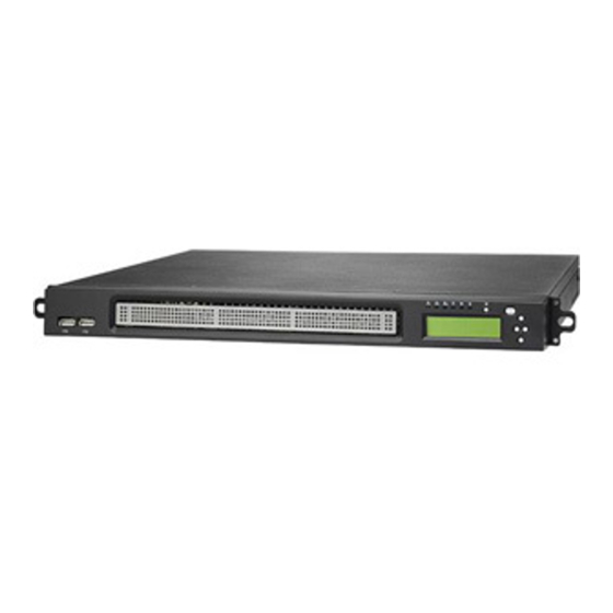
- Page 1 Tank™ GT14 B5180 Service Engineer’s Manual...
- Page 3 TYAN retains the right to make changes to product descriptions and/or specifications at any time, without notice. In no event will TYAN be held liable for any direct or indirect, incidental or consequential damage, loss of use, loss of data or other malady resulting from errors or inaccuracies of information contained in this document.
- Page 4 Federal Communication Commission (FCC) Notice for the USA Compliance Information Statement (Declaration of Conformity Procedure) DoC FCC Part 15: This device complies with part 15 of the FCC Rules Operation is subject to the following conditions: This device may not cause harmful interference; This device must accept any interference received including interference that may cause undesired operation.
- Page 5 About this Manual This manual provides you with instructions on installing your Tank™GT14. This Manual is intended for experienced users and integrators with hardware knowledge of personal computers. This manual consists of the following parts: Chapter1: Provides an introduction to the GT14 B5180 barebones, packing list, describes the external components, gives a table of key components, and provides block...
- Page 6 SAFETY INFORMATION Before installing and using the Tank™GT14, take note of the following precautions: – Read all instructions carefully. – Do not place the unit on an unstable surface, cart, or stand. – Do not block the slots and opening on the unit, which are provided for ventilation.
-
Page 7: Table Of Contents
Table of Contents Chapter 1: Overview 1.1 About the Tank™ GT14 B5180…………………….……...…….…………. 1.2 Product Models…………………..……………………….………....1.3 Features……………………………………………………………………… 1.4 Unpacking………………………………….……..………......1.5 About the Product……….………………………..……......... 1.5.1 System Front View………………………..…………………………. 1.5.2 System Rear View………………………………........ 1.5.3 LED Definition……………………………………………………..1.5.4 Internal View………………………………………………………..1.5.5 Motherboard Layout………………………......... 1.5.6 Jumpers &... - Page 8 3.3 Removing the Top Chassis Cover……………………..…….……………..3.4 Replacing Motherboard Components……………..………………………… 3.4.1 Disconnecting All Motherboard Cables………………....... 3.4.2 Removing the Motherboard………………………………………….. 3.5 Replacing the LCD Module and LED Board….……........3.5.1 M1017 LED Board Features………………………......3.5.2 M1007 LED Board Connector Pin Definition………………………. 3.6 Replacing the USB Board…………………………………………………… 3.6.1 USB Board Features………………..………………………………..
-
Page 9: Chapter 1: Overview
IT environment but also offers a smooth path for future application usage. TYAN is also proud to deliver the Tank™ GT14 B5180 in SATAII flavor while supporting up to three (3) hard drives. The Tank™ GT14 B5180 uses TYAN’s latest chassis featuring a robust structure and a solid mechanical enclosure. -
Page 10: Features
DIMM Type / Speed 800/667/533 Memory Capacity Up to 4GB Memory channel 2-Channel Memory voltage 1.5V PCI-E (1) PCI-E x16 slot Expansion Slots Pre-install TYAN M2083-RS, PCI-E x16 1U riser card (left) Riser Card Port QTY Controller Intel 82573V Chapter 1: Overview... - Page 11 RoHS Complaint Motherboard (1) S5180G2N-BB Manual (1) User's manual / (1) Quick Ref. Guide Package Installation CD (1) TYAN installation CD Contains Chassis Unit (1) CCHA-0240, GT14 1U chassis unit Cover (1) CCCV-0110, Top cover for GT14 Chapter 1: Overview...
- Page 12 (1) CHDT-0111, Internal 2.5" HDD bracket / (1) CHDT-0120, Internal 3.5" HDD Tray HDD bracket - L / (1) CHDT-0121, Internal 3.5" HDD bracket - R (2) CFAN-0310, 4 cm fans / (1) CFAN-0270, 4 cm fan / (1) CHSK-0131, Heatsink / Cooler LGA775 CPU heatsink / (1) CADT-0190, air duct...
- Page 13 Speed Memory Capacity Up to 4GB Memory channel 2-Channel Memory voltage 1.5V PCI-E (1) PCI-E x16 slot Expansion Pre-install TYAN Slots M2083-RS, PCI-E x16 1U riser card (left) Riser Card Port QTY Controller Intel 82573V Connector type D-Sub 15pin Graphic...
- Page 14 Motherboard (1) S5180G2N-BB Manual (1) User's manual / (1) Quick Ref. Guide Installation CD (1) TYAN installation CD Chassis Unit (1) CCHA-0240, GT14 1U chassis unit Cover (1) CCCV-0110, Top cover for GT14 (1) CHDT-0111, Internal 2.5" HDD bracket / (1) CHDT-0120, Internal 3.5"...
- Page 15 Cable SATA (1) CCBL-0328, SATA signal cable, 150mm / (1) CCBL-0329, SATA signal cable, 200mm / SATA (1) CCBL-032A, SATA signal cable, 300mm Package Contains (1) CCBL-0352, USB cable, 350mm Cable Front (1) CCBL-0727, front panel cable, 500mm Panel Power (1) CCBL-0310, US type power cord / (1) Cord CCBL-0300, EU type power cord...
-
Page 16: Unpacking
Unpacking If any items are missing or appear damaged, contract your retailer or browse to TYAN’s website for service: http://www.tyan.com The Web site also provides information on other TYAN products, plus FAQs, compatibility lists, BIOS settings, and more. Power Cables... - Page 17 Rail Kit (Optional) Rail Kit options: A, B, C The following three rail kits are available to rackmount your GT14 B5180. A. Rail for 4-post rack Sliding Rails x 2 Sliding Brackets x 4 (Front L-Bracket x 2, Rear L-Bracket x2) Mounting Brackets x 4 M4-4L screw x 18pcs M5-8L screw x 10pcs...
- Page 18 C. Rail for 4-post rack Inner Rails x 2 Post Slide Mount Adapters x 4 Assembled Outer Sliding Rails x 2 M4-4L screw x 30pcs M5-8L screw x 10pcs M5-15L screw x 4pcs NOTE: For detailed information on rail kit of C, please contact our sales representative.
-
Page 19: About The Product
About the Product The following views show you the product. 1.5.1 System Front View LCD Display USB Port x 2 1.5.2 System Rear View B5180G14S3M: Power Supply Fan PCI-E Slot Power Supply Socket LAN Port x 2 PS/2 Mouse/ VGA Port Keyboard Ports USB Port x 4 Serial Port... - Page 20 B5180G14S3M-QT: Power Supply Socket PCI-E Slot Power Supply Fan LAN Port x 2 PS/2 Mouse/ VGA Port Keyboard Ports Serial Port USB Port x 4 Chapter 1: Overview...
-
Page 21: Led Definition
1.5.3 LED Definition Front Panel Color State Description Green Power ON Power —— Power OFF Amber Blinking HDD access HDD Access —— No disk activity Green LAN Linked LAN1/LAN2 Activity Green Blinking LAN Accessing —— No LAN linked System fails (fan fail/over Warning voltage/over temperature) ——... -
Page 22: Internal View
1.5.4 Internal View B5180G14S3M: 1. PCI-E Riser Card 3.5” Hard Disk Drive Bracket (Right) 2. Air Duct Chassis Front Bezel 3. Power Connector 3.5” Hard Disk Drive Bracket (Left) 4. Power Supply System Fans 5. Memory Slot 10. 2.5” Hard Disk Drive Bracket Chapter 1: Overview... - Page 23 B5180G14S3M-QT: 1. PCI-E Riser Card 3.5” Hard Disk Drive Bracket (Right) 2. Air Duct Chassis Front Bezel 3. Power Connector 3.5” Hard Disk Drive Bracket (Left) 4. Power Supply System Fans 5. Memory Slot 10. 2.5” Hard Disk Drive Bracket Chapter 1: Overview...
-
Page 24: Motherboard Layout
1.5.5 Motherboard Layout This diagram is representative of the latest board revision available at the time of publishing. The board you receive may not look exactly like the above diagram. Chapter 1: Overview... -
Page 25: Jumpers & Connectors
1.5.6 Jumpers & Connectors Jumper/Connector Function JP13 USB Pin Header (5_Pin x 2) JP16 Front Panel Header 1 (9_Pin x 2) JP23 FAN Connector (4_Pin x 1) J102, J103 FAN Connector (8_Pin x 1) JP24, JP25 LANA SMBus Selection (5_Pin x 2) JP30 CMOS Clear SMDC Connector (25_Pin x 2) -
Page 26: Jp13 Usb Pin Header (5_Pin X 2)
Jumper Placement J102 J103 JP23 JP16 JP13 JP13: USB Pin Header (5Pin x 2) Signal Signal +5VPWR +5VPWR DATA1- DATA2- DATA1+ DATA2+ Use this header to connect to the USB devices via the enclosed USB cable. Chapter 1: Overview... -
Page 27: Jp16 Front Panel Header 1 (9_Pin X 2)
JP16: Front Panel Header 1 (9Pin x 2) Signal Signal HD LED+ PW LED+ HD LED- PW LED- Reset S/W PWR S/W Reset S/W PWR S/W 3.3V WLED+ EXT_NMI WLED- 5VSB INTRUDER# JP23: FAN Connector (4Pin x 1) Signal +12V TACH Pin_1 J102/J103: FAN Connector (8Pin x 1) - Page 28 JP30 JP25 JP24 JP24/JP25: LANA SMBus Selection (3Pin x 1) Use jumper cap to close Pin_1 and Pin_2 : Pin_1 Pin_3 Connect LANA SMBus to motherboard SMBus; Use jumper cap to close Pin_2 and Pin_3: Pin_1 Pin_3 Connect LANA SMBus to SMDC SMBus; Chapter 1: Overview...
-
Page 29: J30 Smdc Connector (25_Pin X 2)
Clear CMOS Clear CMOS Reconnect power & power on system J30: SMDC Connector (25Pin x 2) For connection with Tyan Server Management Daughter Card (SMDC). The SMDC connector is compatible with only the Tyan M3291 (SMDC). J100 J101 Chapter 1: Overview... -
Page 30: J101 Front Panel Header 2 (6_Pin X 2)
J100: Chassis LCD Module Interface Header (3Pin x 2) Signal Signal +5VPWR +5VSB SOUT J101: Front Panel Header 2 (6Pin x 2) Signal Signal LAN1_LED+ LAN1_LED- LAN2_LED+ LAN1_LED- IDLED+ IDLED- IDSW+ IDSW- Chapter 1: Overview... -
Page 31: System Block Diagram
1.5.7 System Block Diagram Chapter 1: Overview... -
Page 32: Fru List
1.5.8 FRU List Item Model Number Picture Quantity Description S5180G2N-BB Single P4, PD, Core 2 Motherboard S5180G2N-BB Motherboard Chassis Unit CCHA-0240 GT14 1U Chassis for B5180 Chassis Top CCCV-0110 GT14 Top Cover Cover Chassis Front CFBZ-0120 Front Bezel for GT14 Series 1U Chassis Bezel CHDT-0111 Internal 2.5"... - Page 33 CCBL-0622 SMDC Cable, 220mm CCBL-046R SATA Power Convert Cable, 50mm NOTE: This FRU List is representative of the latest revision available at the time of publishing. Any update of the contents, please visit: www.tyan.com for more details. Chapter 1: Overview...
- Page 34 Chapter 1: Overview...
-
Page 35: Chapter 2: Setting Up
Chapter 2: Setting Up 2.0.1 Before you Begin This chapter explains how to install the CPU, CPU heatsink, memory modules, 2.5” hard drive, 3.5” hard drive and PCI-E card. 2.0.2 Work Area Make sure you have a stable, clean working environment. Dust and dirt can get into components and cause malfunctions. -
Page 36: Precautions
2.0.4 Precautions Components and electronic circuit boards can be damaged by discharges of static electricity. Working on a system that is connected to a power supply can be extremely dangerous. Follow the guidelines below to avoid damage to the Tank GT14 B5180 or injury to yourself. -
Page 37: Installing Motherboard Components
Installing Motherboard Components This section describes how to install components on to the motherboard, including CPU, memory modules and a PCI-E card. 2.1.1 Removing the Chassis Top Cover Follow these instructions to remove the Tank GT14-B5180 chassis top cover. Remove the screw on the back side as shown in the small diagram and tow on the top of the chassis top cover. -
Page 38: Installing The Cpu And Heatsink
2.1.2 Installing the CPU and Heatsink Follow these instructions on install CPU and CPU heatsink. Remove the air duct in the direction of the arrow shown to locate the CPU socket. Remove the CPU socket cover. Pull the CPU lever up to unlock the CPU socket (A) and open the socket in the direction as shown (B). - Page 39 4. Place the CPU on the CPU socket, ensuring that pin 1 is located as shown in the smaller diagram. And then close the CPU socket cover (A) and press the CPU socket lever down to secure the CPU (B). 5.
-
Page 40: Installing The Memory
2.1.3 Installing the Memory Follow these instructions to install the memory modules on the motherboard. Your GT14-B5180 has totally 2 DIMM sockets. 1. Press the memory slot locking levers in the direction of the arrows as shown in the following illustration. 2. -
Page 41: Installing The Pci-E Card
2.1.4 Installing the PCI-E Card The GT14-B5180 has one PCI-E Card slot: PCI-E x 16 card slot Follow these instructions to install the PCI-E card. Remove the screw securing the tab of PCI-E slot from the rear side of your GT14 B5180 system. Pull the tab of PCI-E slot on the rear side in the direction as shown to release the I/O shield. - Page 42 Insert PCI-E card into the PCI-E riser in the direction of arrows as shown. Push the tab of PCI slot on the rear side in the direction as shown to fix the PCI-E Card. And secure the tab of PCI-E slot on the rear side with one screw as shown. Chapter 2: Setting Up...
-
Page 43: Installing The Hard Drive
2.1.5 Installing the Hard Disk Driver The GT14 chassis kit supports up to two 3.5” SATAII hard drives and one 2.5” SATAII hard drive without SMDC support. Refer to the following HDD Configuration Table and Location Diagram before installing Hard Driver. HDD Configuration Table 3.5”... - Page 44 2.1.5.1 Installing the 3.5” Hard Drive (Left) Follow these instructions to install the left 3.5” SATA hard drive. Remove the screw securing the 3.5” drive bracket in the GT14 chassis. Slide the drive tray out (A) and lift the bracket out from the chassis (B).
- Page 45 Place the assembled hard drive with bracket in the spot you picked from the GT14 chassis (A) and slide it into place (B). And secure it with the screw removed in step Connect the SATA drive data and power connectors. Chapter 2: Setting Up...
- Page 46 2.1.5.2 Installing the 3.5” Hard Drive (Right) Follow these instructions to install the right 3.5” SATA hard drive. 1. Remove the two screws securing the 3.5” drive bracket in the GT14 chassis. 2. Slide the drive tray out (A) and lift the bracket out from the chassis (B).
- Page 47 4. Place the assembled hard drive with bracket in the spot you picked from the GT14 chassis (A) and slide it into place (B). And secure it with the two screw removed in step 1. 5. Connect the SATA drive data and power connectors. Chapter 2: Setting Up...
- Page 48 2.1.5.3 Installing the 2.5” Hard Drive Follow these instructions to install the 2.5” SATA hard drive. 1. Remove the screw securing the 2.5” drive bracket in the GT14 chassis. 2. Slide the drive tray out (A) and lift the bracket out from the chassis (B).
- Page 49 4. Place the assembled hard drive with bracket in the spot you picked from the GT14 chassis (A) and slide it into place (B). And secure it with the screw removed in step 5. Connect the SATA drive data and power connectors. Chapter 2: Setting Up...
-
Page 50: Rack Mounting
Rack Mounting After installing the necessary components, the Transport GT14 can be mounted in a rack using the supplied rack mounting kit. The screw types are listed below for your reference. Screws List Rail for 4-post rack (Rail kit A) Item Screw Size... -
Page 51: Installing The Server In A Rack (With Rail Kit A)
2.2.1 Installing the Server in a Rack (with Rail kit A) Follow these instructions to mount the GT14 into an industry standard 19" rack. (Rail kit A) NOTE: Before mounting the Transport GT14 in a rack, ensure that all internal components have been installed and that the unit has been fully tested. - Page 52 3. Install inner rails to left and right sides of chassis using 1 M4-4L(A) screw for each side. Chapter 2: Setting Up...
- Page 53 Installing Outer Rails to the Rack 4. Measure the distance between inner side of the front and rear mounting brackets in the rack. 5. Reserve the distance same as in step 4 on rear racket. Secure the rear bracket to outer rail with 2 M4-4L(A) screws.
- Page 54 Rackmounting the Server 7. Draw out the middle rails to the latch position. 8. Lift the chassis and then insert the inner slide rails into the middle rails. 9. Push the chasis in and press the latch key (A). Then push the whole system into the rack(B).
- Page 55 10. Secure the mounting ears of chassis to the rack with one M4-15L(F) screw for each side. NOTE: To avoid injury, it is strongly recommended that two people lift the GT14 into the place while a third per- son screws it to the rack. Chapter 2: Setting Up...
-
Page 56: Installing The Server In An Open Rack (With Rail Kit B)
2.2.2 Installing the Server in an Open Rack (with Rail kit B) In addition to rackmounting the GT14 in a 4-post rack, you can also mount it in a 2-post rack. You must use rail kit B to mount the GT14 in this type of rack. 2-post open rack NOTE: Before mounting the Transport GT14 in a rack, ensure that all internal components have been installed and that the... - Page 57 2. Lift the chassis and secure the mounting brackets to the front of rack using 3 M5-8L(D) screws for each side. NOTE: To avoid injury, it is strongly recommended that two people lift the GT14 into the place while a third per- son screws it to the rack.
- Page 58 4. Slide the mounting brackets into the rear of inner rail brackets as shown. 5. Secure the mounting brackets with three M4-4L(E) screws for each side. 6. The GT14 has been mounted to the rack as shown. Chapter 2: Setting Up...
-
Page 59: Rack Mount Instructions
2.2.3 Rack Mount Instructions Follow these instructions to mount your GT14-B5180 into an industry standard 19” rack. Elevated Operating Ambient - If installed in a closed or multi-unit rack assembly, the operating ambient temperature of the rack environment may be greater than room ambient. Therefore, consideration should be given to installing the equipment in an environment compatible with the maximum ambient temperature (Tma) specified by the manufacturer. -
Page 60: Lcd Software Setup
IP address assigned to the system • Subnet mask of your network’ 2.3.2 M1000 Driver Installation for Windows Step 1. Install TYAN TSM program. Step 2. Install M1000 driver for Windows. 2.3.3 M1000 Driver Installation for Linux Step 1. Install M1000 driver for Linux... -
Page 61: Lcd Console
4. Down: Go to the next selection. After you have installed the TYAN TSM and M1000 driver for Windows (for Windows OS) or the M1000 driver for Linux (for Linux OS), you can use the LCD front panel control but- tons to get access to the information under each submenu. -
Page 62: Dos Mode And Windows Mode
2.4.2 DOS Mode and Windows Mode M1000 supports both DOS Mode and Windows Mode. DOS Mode BIOS Info Model Name DOS Mode CPU Info RAM Info Item Screen Display BIOS Info V1.02.B11 Tank GT14 Model Name MODEL: B5180 CPU Info CPU: xxxx MHz Memory Info Memory: xxxx MB... - Page 63 Windows Mode Performance Memory Hard Disk Net Interface System Sensors Voltage Temperature Power Down Power Ctl Reboot Item Screen Display TYAN Computer Host Name GT14 B5180 System Nics NIC0 DHCP IP Address: xx.xx.x.xxx Net Mask: xxx.xxx.xxx.0 Gateway: xxx.xxx.xxx.0 NIC1 DHCP IP Address: xx.xx.x.xxx...
- Page 64 Item Screen Display TYAN Computer Host GT14 B5180 Name Performance CPU Usage x.xx% Memory Memory Usage Hard Disk Disk Usage x.xx% NIC0 Flow Speed x Bps Net Interface NIC1 Flow Speed x Bps System Sensors Chassis Fan 1 xxxxRPM Chassis Fan 2...
-
Page 65: Linux Mode
Linux Mode Performance Memory Hard Disk Net Interface System Sensors Voltage Temperature Power Down Power Ctl Reboot Item Screen Display TYAN Computer Host Name GT14 B5180 System Nics NIC0 DHCP IP Address: xx.xx.x.xxx Net Mask: xxx.xxx.xxx.0 Gateway: xxx.xxx.xxx.0 NIC1 DHCP IP Address: xx.xx.x.xxx... - Page 66 Item Screen Display TYAN Computer Host GT14 B5180 Name Performance CPU Usage x.xx% Memory Memory Usage Hard Disk Disk Usage x.xx% NIC0 Flow Speed x Bps Net Interface NIC1 Flow Speed x Bps System Sensors Chassis Fan 1 xxxxRPM Chassis Fan 2...
-
Page 67: Chapter 3: Replacing Pre-Installed Components
Chapter 3: Replacing Pre-Installed Components Introduction This chapter explains how to replace pre-installed components, including the Motherboard, LCD Module, cooling fans and power supply. 3.1.1 Work Area Make sure you have a stable, clean working environment. Dust and dirt can get into components and cause malfunctions. -
Page 68: Precautions
3.1.3 Precautions Components and electronic circuit boards can be damaged by discharges of static electricity. Working on a system that is connected to a power supply can be extremely dangerous. Follow the guidelines below to avoid damage to the Tank GT14 B5180 or injury to yourself. -
Page 69: Disassembly Flowchart
Disassembly Flowchart The following flowchart outlines the disassembly procedure. Rear Components Chassis top cover Mainboard Power Supply FANs DIMMs CPU/Heatsink Mainboard Assembly PCI-E Card Front Components Chassis front bezel PCBs Front LED Module Board Board Chapter 3: Replacing Pre-Installed Components... -
Page 70: Removing The Top Chassis Cover
Removing the Chassis Top Cover Before replacing any parts you must remove the chassis cover. Follow these instructions to remove the cover of the Tank GT14 chassis cover. Remove the screw on the back side as shown in the small diagram and two on the top of the chassis top cover. -
Page 71: Replacing Motherboard Components
Replacing Motherboard Components Follow these instructions to replace motherboard components, including the motherboard. 3.4.1 Disconnecting All Motherboard Cables Before replacing the motherboard or certain components, remove cables connected to the motherboard. Follow these instructions to remove all motherboard cabling. 1. Disconnect Power Cables. 2. -
Page 72: Removing The Motherboard
3.4.2 Removing the Motherboard After removing all of the aforementioned cables, follow these instructions to remove the motherboard from the chassis. Remove the five screws securing the motherboard to the chassis. Remove the motherboard. Chapter 3: Replacing Pre-Installed Components... -
Page 73: Replacing The Lcd Module And Led Board
Replacing the LCD Module and LED Board Follow these instructions to replace the LCD module and LED Board in your GT14 B5180 system. Remove the chassis front bezel as shown. Remove the two screws securing the LCD module. Disconnect the LCM and control board cable. Chapter 3: Replacing Pre-Installed Components... - Page 74 Remove the four screws on both sides of the LCD module. Remove the LCD front bracket from the LCD module. Remove the two screws from the rear LCD bracket. Chapter 3: Replacing Pre-Installed Components...
- Page 75 Remove the three screws securing the LED board to the rear LCD bracket. Remove the LED board. Place a new LCD module in position in the chassis following the above steps in reverse. Chapter 3: Replacing Pre-Installed Components...
-
Page 76: M1017 Led Board Features
3.5.1 M1017 LED Board Features Warning LED LAN1 LED Power Button ID Button LAN2 LED Power LED HDD Access LED ID LED 3.5.2 M1017 LED Board Connector Pin Definition 2 x 14 Pin Header Chapter 3: Replacing Pre-Installed Components... -
Page 77: Replacing The Usb Board
Replacing the USB Board Follow these instructions to replace the USB board in your GT14 B5180 system. 1. Remove the chassis front bezel as step 1 in “3.5 Replacing the LCD Module and LED Board”. 2. Disconnect the USB cable from the USB board. 3. -
Page 78: Usb Board Features
3.6.1 USB Board Features USB 2x5 Pin Headers USB1 USB2 3.6.2 USB Board Connector Pin Definition 2 x 5 Pin USB Header Definition Definition USB1 POWER USB2 POWER USB1 DATA- USB2 DATA- USB1 DATA+ USB2 DATA+ USB1 GND USB2 GND KEY PIN NONE Chapter 3: Replacing Pre-Installed Components... -
Page 79: Replacing The Cooling Fans
Replacing the Cooling Fans Follow these instructions to replace the cooling fans in your B5180G14S3M system. The same operation sequence is applicable to the B5180G14S3M-QT SKU, but the detailed fans cable connections please refer to Appendix I, Table 3. 1. Remove the three fan connectors from the motherboard. 2. -
Page 80: Replacing The Power Supply
Replacing the Power Supply Follow these instructions to replace the power supply in your B5180G14S3M system. The same operation sequence is applicable to the B5180G14S3M-QT SKU. Disconnect the power cables from the motherboard. Refer to “3.4.1 Disconnecting All Motherboard Cables” for more details. Remove the two screws securing the power supply to the chassis. - Page 81 For B5180G14S3M-QT SKU, remove three screws securing the power supply to the front power bracket as below. Lift the power supply with its bracket free from the chassis. Free the power supply from its bracket by removing the two screws. Replace a new power supply into the chassis following the above steps in reverse.
- Page 82 Chapter 3: Replacing Pre-Installed Components...
-
Page 83: Chapter 4: Bios Setup
Chapter 4: BIOS Setup Installation The BIOS is the basic input/output system, the firmware on motherboard that enables your hardware to interface with your software. This chapter describes different settings for the BIOS that can be used to configure your system. The BIOS section of this manual is subject to change without notice and is provided for reference purposes only. -
Page 84: Setup Basics
In particular, do not change settings in the Chipset section unless you are absolutely sure of the outcome. The Chipset defaults were carefully chosen by TYAN or your system manufacturer for the best performance and reliability. Even a seemingly small change to the Chipset setup options may cause the system to become unstable or unusable. -
Page 85: Main Bios Setup
4.1 – Main BIOS Setup When you enter Phoenix - AwardBIOS CMOS Setup Utility, the following screen will appear as below: Phoenix – AwardBIOS CMOS Setup Utility ► Frequency/Voltage Control ► Standard CMOS Features ► Advanced BIOS Features Load Fail-Safe Defaults ►... - Page 86 Use this menu to load the BIOS default values for the minimal/stable performance for your system to operate. Load Optimized Defaults: Use this menu to load the BIOS default values that are factory settings for optimal performance system operations. While Award has designed the custom BIOS to maximize performance, the factory has the right to change these defaults to meet their needs.
-
Page 87: Standard Cmos Features
4.2 – Standard CMOS Features In this section, you can alter general features such as the date and time, as well as access to the IDE configuration options. Note that the options listed below are for options that can directly be changed within the Main Setup screen. - Page 88 IDE Master / Slave Setup: Computer detects IDE drive type from drive C to drive F. None / Auto / Manual Video: Define the video display mode. EGA/VGA / CGA 40 / CGA 80 / MONO Halt On: Determine if the computer should stop when an error is detected during power up.
-
Page 89: Phoenix - Awardbios Cmos Setup Utility
4.2.1 Phoenix – AwardBIOS CMOS Setup Utility IDE Channel 1 Master Auto- [Press Enter] Item Help Detection _________________________ [Auto] IDE Channel 1 Master [Auto] Menu Level ► Access Mode 80GB To auto-detect the HDD’s size, Capacity head…on this channel 38309 Cylinder Head Precomp... -
Page 90: Advanced Bios Features
4.3 – Advanced BIOS Features In Advanced BIOS features, you will be able to adjust many of the feature that effect system speed and boot-up options. Phoenix – AwardBIOS CMOS Setup Utility Advanced BIOS Features ►CPU Feature [Press Enter] Item Help ►Hard Disk Boot Priority [Press Enter] ___________... - Page 91 First, Second, and Third Boot Devices: These indicate the boot priority. For example if the First Boot Device is set as CDROM, the Second Boot Device as Hard Disk, and the Third Boot Device as LS120, then the system will try to boot from CDROM, failing which it will try to boot from a Hard Disk, and if this also fails, it will try to boot from the LS120.
- Page 92 when the logo test executes. 1.1 / 1.4 OS Select For DRAM>64MB: This BIOS feature determines how systems with more than 64MB of memory are managed. A wrong setting can cause problems like erroneous memory detection. If you are using an older version of the IBM OS/2 operating system, you should select OS/2.
-
Page 93: Cpu Features
4.3.1 – CPU Features Press [Enter] to access advanced features of the CPU. Phoenix – AwardBIOS CMOS Setup Utility CPU Feature Limit CPUID MaxVal [Disabled] Item Help C1E Function [Auto] ______________ Execute Disable Bit [Enabled] __________ Virtualization Technology [Enabled] Menu Level ► ↑↓←→: Move Enter: Select +/-/PU/PD: Value F10: Save ESC: Exit F1: General Help F5: Previous Values F6: Fail-Safe Defaults F7: Optimized Defaults... -
Page 94: Hard Disk Boot Priority
4.3.2 – Hard Disk Boot Priority Select 〔Press Enter〕to set Hard Disk Boot Priority Phoenix – AwardBIOS CMOS Setup Utility Hard Disk Boot Priority 1. Ch1 M ST380013AS Item Help 2. Bootable Add-in Cards ____________________ ____ Menu Level ► Use (↑) or (↓) to select a device, then press<+>... -
Page 95: Advanced Chipset Features
4.4 – Advanced Chipsets Features In Advanced Chipset Features, you will be able to adjust many of the chipset special features. Phoenix – AwardBIOS CMOS Setup Utility Advanced Chipset Features System BIOS Cacheable [Enabled] Item Help Memory Hole At 15M-16M [Disabled] _________________ ________... -
Page 96: Integrated Peripherals
DVMT/FIXED Memory Size: When set to DVMT Mode, the graphics chip will dynamically allocate system memory as graphics memory 128MB / 256MB / MAX 4.5 – Integrated Peripherals Options related to onboard peripheral features can be altered through the following: Phoenix –... -
Page 97: Onchip Ide Device
4.5.1 – OnChip IDE Device Phoenix – AwardBIOS CMOS Setup Utility OnChip IDE Device IDE HDD Block Mode [Enabled] Item Help IDE DMA Transfer Access [Enabled] ______________________ IDE Primary Master PIO [Auto] IDE Primary Slave PIO [Auto] IDE Primary Master UDMA [Auto] Menu Level ►►... -
Page 98: Phoenix - Awardbios Cmos Setup Utility
operating environment includes a DMA driver (Windows 95 OSR2 or a third-party IDE bus master driver). If your hard drive and your system software both support Ultra DMA/33, select Auto to enable bios SUPPORT. Auto / Disabled On-Chip Secondary PCI IDE: IDE hard drive controllers can support up to two separate hard drives. - Page 99 Item Help USB 1.0 Controller [Enabled] ________________ USB 2.0 Controller [Enabled] _________ USB Operation Mode [High Speed] USB Keyboard Function [Enabled] Menu Level ►► USB Mouse Function [Enabled] USB Storage Function [Enabled] *USB Mass Storage Device Boot Setting* ↑↓←→: Move Enter: Select +/-/PU/PD: Value F10: Save ESC: Exit F1: General Help F5: Previous Values F6: Fail-Safe Defaults F7: Optimized Defaults USB Controller:...
-
Page 100: Super Io Device
USB Operation Mode: Auto decide USB device operation mode. Full/Low Speed / High Speed USB Keyboard Support: Select “Enabled” if your system contains a USB controller and you have a USB keyboard. Enabled / Disabled USB Mouse Support: Set this option to be enabled if your system has a USB controller (including USB 2.0) and a USB mouse. -
Page 101: Power Management Setup
4.6 – Power Management Setup Options related to power management can be altered through the following: Phoenix – AwardBIOS CMOS Setup Utility Power Management Setup ACPI Function [Enabled] Item Help Run VGABIOS if S3 Resume [Auto] ______________ Power Management [User Define] ___________ Video Off Method [DPMS]... - Page 102 Power Management: This function allows you to set the default parameters of power-saving modes. Set this to User Define to choose your own parameters. The following table shows the parameters for Maximum Saving and Minimum Saving options for the various modes: Mode Doze Standby...
- Page 103 Intruder# Detection: This feature is used to enable/disable the function: when chassis open event is detected, BIOS will record the event. Disabled/ Enabled PWRON After PWR-Fail: When the system is shut down owing to the power failure, the system will not be back to power on by itself. This feature allows you to set the system back to which power status of the system when the system power is resumed.
-
Page 104: Pnp/Pci Configurations
4.7 – PnP/PCI Configurations Options related to all the configurations of PnP / PCI resources. Phoenix – AwardBIOS CMOS Setup Utility PnP / PCI Configurations Init Display First [PCI Slot] Item Help Reset Configuration Data [Disabled] _____________ ____________ Resources Controlled By [Auto (ESCD)] X IRQ Resources Press Enter... -
Page 105: Pc Health Status
INT Pin 1/2/3/4/5/6/7/8 Assignment: This feature allows you to assign the PCI IRQ numbers for PCI slots. Selecting the default, Auto, allows the PCI controller to automatically allocate the IRQ numbers. Auto / 3 / 4 / 5 / 7 / 9 / 10 / 11 / 12 / 14 / 15 Maximum Payload Size [128]: This setting defines the maximum payload size. - Page 106 B5180G14S3M-QT: ►Fan control [Press Item Help CPU Temperature Enter] _____________________ Tcase/thermal 30℃ ____ diode MCH Temperature 37℃ Menu Level ► Vccp 1.33V V5SB 5.38V 12.27V 5.38V System FAN1 10131RPM System FAN2 6976RPM System FAN3 4530RPM ↑↓←→: Move Enter: Select +/-/PU/PD: Value F10: Save ESC: Exit F1: General Help F5: Previous Values F6: Fail-Safe Defaults F7: Optimized Defaults Note:...
-
Page 107: Autofan Control
4.8.1 – AutoFAN Control AutoFan ctrl [Enabled] Item Help CPU Select [Conroe/Cedar Mill] ___________________ Duty Cycle/System/ ______ [10%] Duty Cycle/CPU/ [15%] Menu Level ► ↑↓←→: Move Enter: Select +/-/PU/PD: Value F10: Save ESC: Exit F1: General Help F5: Previous Values F6: Fail-Safe Defaults F7: Optimized Defaults AutoFan Control: This feature is used to set function of Auto Mode Fan Control. -
Page 108: Frequency/Voltage Control
CPU Clock Ratio: The CPU clock ratio setting defines how fast the CPU clock runs relative to the bus speed. TYAN does not recommend changing this setting from the default setting. Min=6, Max=7.The default is 7x. Chapter 4: BIOS Setup... -
Page 109: Load Fail-State Default
4.10 – Load Fail-Safe Defaults Phoenix – AwardBIOS CMOS Setup Utility ► Standard CMOS Features ► Frequency/Voltage Control ► Advanced BIOS Features Load Fail-Safe Defaults ► Advanced Chipset Features Load Optimized Defaults ► Integrated Peripherals Set Supervisor Password ► Power Management Setup Set User Password Load Fail-Safe Defaults (Y/N)? N ►... -
Page 110: Supervisor/User Password Setting
4.12 – Supervisor/User Password Setting Phoenix – AwardBIOS CMOS Setup Utility ► Standard CMOS Features ► Frequency/Voltage Control ► Advanced BIOS Features Load Fail-Safe Defaults ► Advanced Chipset Features Load Optimized Defaults ► Integrated Peripherals Set Supervisor Password ► Power Management Setup Set User Password Enter Password: ►... -
Page 111: Exit Selection
Type the password, up to eight characters in length, and press <Enter>. The password typed now will clear any previously entered password from CMOS memory. You will be asked to confirm the password. Type the password again and press <Enter>. You may also press <Esc> to abort the selection and not enter a password. - Page 112 Save to CMOS and EXIT (Y/N)? Y Pressing “Y” stores the selections made in the menus in CMOS – a special section of memory that stays on after you turn your system off. The next time you boot your computer, the BIOS configures your system according to the Setup selections stored in CMOS.
-
Page 113: Appendix I: Cable Connection Tables
Appendix I: Cable Connection Tables SATA Cables Table 1: GT14 B5180 HDD to Motherboard Connect to Motherboard → HDD 1 SATA 1 → HDD 2 SATA 2 → HDD 3 SATA 3 FAN Cables Table 2: System Fan to Motherboard (For B5180G14S3M) Connect to Motherboard... - Page 114 Other Cables Table 5: M1017 Front Panel LED Board Related Cable M1017 Motherboard JP16 Connector → M1017 LED Connector J101 Connector Table 6: USB Board Related Cable → USB Board Motherboard → USB 2 x 5 pin header JP13 Connector Table 7: LCD Module Related Cable →...
-
Page 115: Appendix Ii: Installing The Smdc Card
Appendix II: Installing the SMDC Card Follow these steps to install M3291 SMDC card onto the 2.5” HDD location on your GT14 chassis. Remove the screw securing the 2.5” hard disk drive bracket in the GT14 chassis. Then slide the drive tray out (A) and lift the bracket out from the chassis (B). - Page 116 Align M3291 with the secured flat screws in step 2. Secure M3291 to the chassis with three screws. Connect the 2 x 25 pin SMDC cable to M3291 as shown. Connect the other end of SMDC cable to the SMDC connector (J30) on the motherboard.
-
Page 117: Appendix Iii: Installing The M2061 Riser Card
Appendix III: Installing the M2061 Riser Card The following provides you with the information on installing the optional M2061 riser card into your GT14 chassis. You need to purchase the M2061 riser card. Remove the M2083 PCI-E riser card from the PCI-E riser card slot. -
Page 118: Appendix Iv: Detaching Lan Cable
Appendix IV: Detaching LAN Cable The following provides instructions on detaching LAN cable. Refer to the first three steps in “2.1.4 Installing the PCI-E Card” to remove the I/O shield. 2. Use the I/O shield as the tool to press the tab on the LAN Cable (A), and draw out the LAN cable at the same time (B). -
Page 119: Appendix V: Assembling Fan Holders
Appendix V: Assembling the Fan Holders The B5180 has totally three fan holders. Refer to the following illustration to assemble them when necessary. NOTE: Make sure the tab fit into the hole of the other fan holder (A) and lock “1” into “2” (B). B5180G14S3M Fan Holder B5180G14S3M-QT... -
Page 120: Technical Support
(which can have expensive consequence). If these options are not available for you then TYAN Computer Corporation can help. Besides designing innovative and quality products for over a decade, TYAN has continuously offered customers service beyond their expectations. - Page 121 RMA number should be prominently displayed on the outside of the shipping carton and the package should be mailed prepaid. TYAN will pay to have the board shipped back to you. TYAN Transport GT14-B5180 User’s Manual v2.00 Document ID: D1899-200...
Need help?
Do you have a question about the Tank GT14 B5180 and is the answer not in the manual?
Questions and answers