Table of Contents
Advertisement
Quick Links
Advertisement
Table of Contents

Related Manuals for TYAN GT24E-B7106


Summary of Contents for TYAN GT24E-B7106
- Page 1 GT24E-B7106 Service Engineer’s Manual...
- Page 2 TECHNOLOGY CORPORATION and has been reviewed for accuracy and reliability prior to printing. MITAC assumes no liability whatsoever, and disclaims any express ® or implied warranty, relating to sale and/or use of TYAN products including liability or warranties relating to fitness for a particular purpose or merchantability. MITAC retains the right to make changes to produce descriptions and/or specifications at any time, without notice.
-
Page 3: Fcc Declaration
FCC Declaration ● Notice for the USA Compliance Information Statement (Declaration of Conformity Procedure) DoC FCC Part 15: This device complies with part 15 of the FCC Rules. This device complies with Part 15 of the FCC Rules. Operation is subject to the following conditions: ‧This device may not cause harmful interference. - Page 4 Warning This equipment is compliant with Class A of CISPR 32. In a residential environment this equipment may cause radio interference. CAUTION Lithium battery included with this board. Do not puncture, mutilate, or dispose of battery in fire. There will be danger of explosion if battery is incorrectly replaced. Replace only with the same or equivalent type recommended by manufacturer.
-
Page 5: About This Manual
How this guide is organized This guide contains the following parts: Chapter 1: Overview This chapter provides an introduction to the TYAN GT24E-B7106 barebones and standard parts list, describes the external components, gives an overview of the product from different angles. -
Page 6: Safety And Compliance Information
Safety and Compliance Information Before installing and using TYAN GT24E-B7106, take note of the following precautions: ·Read all instructions carefully. ·Do not place the unit on an unstable surface, cart, or stand. ·Do not block the slots and opening on the unit, which are provided for ventilation. -
Page 7: Safety Information
You must become familiar with the safety information in this guide before you install, operate, or service TYAN products. Symbols on Equipment Caution. This symbol indicates a potential hazard. - Page 8 · Make sure racks are coupled together if it is a multiple-rack installation. · Make sure the rack is level and stable before installing an appliance in the rack. · Make sure the leveling jacks are extended to the floor. http://www.tyan.com...
- Page 9 · In all European electrical environments, you must ground the Green/Yellow tab on the power cord. If you do not ground the Green/Yellow tab, it can cause an electrical shock due to high leakage currents. http://www.tyan.com...
- Page 10 TYAN, your authorized TYAN partner, or their agents. Equipment Modifications · Do not make mechanical modifications to the system. TYAN is not responsible for the regulatory compliance of TYAN equipment that has been modified.
- Page 11 – Liquid has been spilled on the product or an object has fallen into the product. – The product has been exposed to rain or water. – The product has been dropped or damaged. – The product does not operate normally when you follow the operating instructions. http://www.tyan.com...
-
Page 12: Table Of Contents
Table of Contents Chapter 1: Overview............... 15 About the TYAN GT24E-B7106 ..........15 Product Model ................ 15 Features .................. 16 Standard Parts List ..............23 1.4.1 Box Contents ..............23 1.4.2 Accessories ............... 23 ... - Page 13 Appendix III: Installing IO Plate for OCP Card ......75 Appendix IV: Cable Connection Tables ........79 Appendix V: Fan and Temp Sensors ..........81 Appendix VI: FRU Parts Table ............85 Appendix VII: Technical Support ..........87 http://www.tyan.com...
- Page 14 NOTE http://www.tyan.com...
-
Page 15: Chapter 1: Overview
® TYAN ’s latest chassis, featuring a robust structure and a solid mechanical enclosure. All of this provides GT24E-B7106 the power and flexibility to meet the needs of nowadays server application. Product Model The system boards within the Tyan barebone systems contain different features and... -
Page 16: Features
Features TYAN GT24E-B7106 (B7106G24EV2E2HR) Form Factor 1U Rackmount Chassis Model GT24E 25.4" x 17.2" x 1.72" (645 x 436 x Dimension (D x W x H) System 43.6mm) Motherboard S7106GM2NR Gross Weight 21 kg (46.5 lbs) Net weight 15.5 kg (34.5 lbs) - Page 17 Intel DDR4 Memory POR Memory channel 6 Channels per CPU Memory voltage 1.2V PCI-E (2) PCI-E Gen3 x16 slots Pre-install TYAN Riser M7106-L16-1F, M7106-R16-1F Card Expansion Slots Others: (1) PCI-E Gen3 x16 OCP 2.0 slots Pre-install TYAN Mezz M7106-4E w/(2) OCuLink x8 connectors...
- Page 18 Operating System OS supported list Please refer to our AVL support lists. FCC (DoC) Class A CE (DoC) Class A Regulation VCCI Class A CB/LVD Class A Operating Operating Temp. 10° C ~ 35° C (50° F~ 95° F) Environment http://www.tyan.com...
- Page 19 Humidity RoHS RoHS 6/6 Compliant (1) Web User's manual, (1) Quick Manual Installation Guide Package Contains Installation CD (1) TYAN installation CD Barebone (1) GT24E-B7106 Barebone TYAN GT24E-B7106 (B7106G24EV4HR) Form Factor 1U Rackmount Chassis Model GT24E 25.4" x 17.2" x 1.72" (645 x 436 x...
- Page 20 Intel DDR4 Memory POR Memory channel 6 Channels per CPU Memory voltage 1.2V PCI-E (2) PCI-E Gen3 x16 slots Pre-install TYAN Riser Expansion Slots M7106-L16-1F, M7106-R16-1F Card Others: (2) PCI-E Gen3 x16 OCP 2.0 slots Port Q'ty (2) GbE ports, (1) PHY...
- Page 21 Feature Configurable FAN PWM Duty Cycle, Console Redirection, ACPI sleeping states S4,S5, ACPI 6.1 Operating System OS supported list Please refer to our AVL support lists. FCC (DoC) Class A CE (DoC) Class A Regulation VCCI Class A CB/LVD http://www.tyan.com...
- Page 22 - 40° C ~ 70° C (-40° F ~ 158° F) Environment In/Non-operating 90%, non-condensing at 35° C Humidity RoHS RoHS 6/6 Compliant (1) Web User's manual, (1) Quick Manual Installation Guide Package Contains Installation CD (1) TYAN installation CD Barebone (1) GT24E-B7106 Barebone http://www.tyan.com...
-
Page 23: Standard Parts List
Standard Parts List This section describes GT24E-B7106 package contents and accessories. Open the box carefully and ensure that all components are present and undamaged. The product should arrive with packaged as illustrated below. 1.4.1 Box Contents If any items are missing or appear damaged, contact your retailer or browse to TYAN’s website for service:... -
Page 24: About The Product
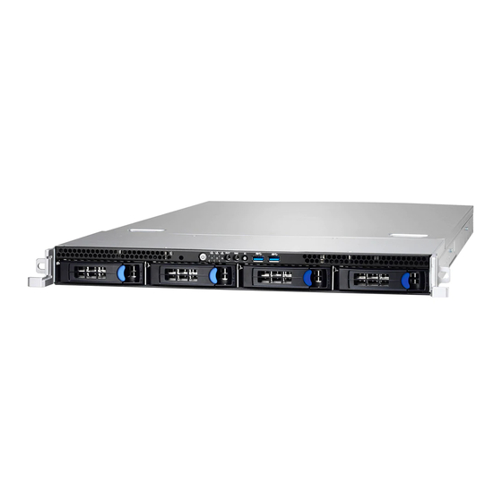
HDD0 HDD1 HDD2 HDD3 M1713G24-FPB Front Panel Board Power Button with green LED ID LED LAN3 LED (no function) Reset Button LAN2 LED NMI Button LAN1 LED ID Button Warning LED USB3.0 Port 2 HDD LED USB3.0 Port 1 http://www.tyan.com... - Page 25 Link / Solid on Green No Function LAN3 LED HDD LED State Color Description Solid On Drive present, no activity Activity LED Green Blinking Drive present, with activity Solid On HDD Failed Status LED Blinking @1Hz Identify Blinking @4Hz Rebuild http://www.tyan.com...
-
Page 26: System Rear View
ID LED will light blue if the system is identified. Users from remote sites can also activate the ID LED by entering a few commands in IPMI. For detailed software support, please visit http://www.tyan.com for the latest AST2500 user guide. - Page 27 The chart below illustrates the different LED states. 10/100/1000 Mbps LAN Link/Activity LED Scheme Left LED Right LED Link Green 10 Mbps Active Blinking Green Link Green Green 100 Mbps Active Blinking Green Green Link Green Amber 1000 Mbps Active Blinking Green Amber No Link http://www.tyan.com...
-
Page 28: System Top View
1.5.3 System Top View (4) Hot-swap HDD trays (1) M1283G24-BP12E-4 HDD Backplane Board (6) System fans M1620G24E-D-PDB Power Distribution Board CPU0 CPU1 (1+1) RPSU Riser Card Bracket (M7106-L16-1F, M7106-R16-1F pre-installed) (2) Internal 2.5” SATA SSD M1713G24-FPB Front Panel Board http://www.tyan.com... -
Page 29: Chapter 2: Setting Up
Caution! To avoid damaging the motherboard and associated components, use torque force within the range kgf/cm (4.35 ~ 6.09 lb/in) on each mounting screw for motherboard installation. Do not apply power to the board if it has been damaged. http://www.tyan.com... -
Page 30: Precautions
Working on a system that is connected to a power supply can be extremely dangerous. Follow the guidelines below to avoid damage to GT24E-B7106 or injury to yourself. Ground yourself properly before removing the top cover of the system. -
Page 31: Installing Motherboard Components
CPUs, memory modules and add on cards. 2.1.1 Removing the Chassis Cover Follow these instructions to remove GT24E-B7106 chassis cover. Remove the screw on the right side, and unscrew the rear top cover on the back side. Slide to lift the rear top cover up. -
Page 32: Installing The Cpu And Heatsink
A new heatsink comes with pre-applied thermal grease. Once the heatsink has been removed from the processor, you need to clean the processor and heatsink using an alcohol solvent. Then apply new thermal grease before reinstalling the heatsink. Take out the protection cap. http://www.tyan.com... - Page 33 To secure the heatsink, use a T30 Security Torx to tighten the screws in a sequential order (1 2 3 4). When disassembling the heatsink, loosen the screws in reverse order (4 3 2 1). http://www.tyan.com...
-
Page 34: Installing The Pci-E Card
2.1.3 Installing the PCI-E Card Follow these instructions to install the PCI-E card. 1. Unscrew the riser card bracket. 2. Remove the riser card bracket from the chassis. 3. Unscrew to remove the dummy brackets from both sides. http://www.tyan.com... - Page 35 4. Insert the PCI-E card into the riser card bracket and screw it firmly. Follow the same procedures to insert the card to the other side of the riser card bracket if necessary. 5. Reposition and screw the riser card bracket into the chassis. http://www.tyan.com...
- Page 36 NOTE: 1. The left and right riser slots are configured as default x16. 2. Internal OCP slot and OCP I/O slot can be configured to x4x4x4x4 / x8x8 / x16. http://www.tyan.com...
-
Page 37: Installing The Memory
Align the memory module with the slot. When inserted properly, the memory slot locking levers lock automatically onto the indentations at the ends of the module. Follow the recommended memory population table to install the other memory modules. http://www.tyan.com... - Page 38 DIMM Location http://www.tyan.com...
- Page 39 √ √ √ √ √ √ P0_MC0_DIM_CH_B0 √ √ √ √ √ √ P0_MC0_DIM_CH_C0 √ √ √ √ √ P0_MC1_DIM_CH_D0 √ P0_MC1_DIM_CH_E1 √ √ √ √ P0_MC1_DIM_CH_E0 √ √ √ P0_MC1_DIM_CH_F0 P1_MC0_DIM_CH_A0 P1_MC0_DIM_CH_B1 P1_MC0_DIM_CH_B0 P1_MC0_DIM_CH_C0 P1_MC1_DIM_CH_D0 P1_MC1_DIM_CH_E1 P1_MC1_DIM_CH_E0 P1_MC1_DIM_CH_F0 http://www.tyan.com...
- Page 40 2. Use paired memory installation for max performance. 3. Populate the same DIMM type in each channel, specifically - Use the same DIMM size - Use the same # of ranks per DIMM 4. Always install with CPU0 Socket first. http://www.tyan.com...
-
Page 41: Installing Hard Drives
2.1.5 Installing Hard Drives The GT24E-B7106 supports four 3.5”/2.5” hot-swap HDD/SSD and two 2.5” internal SSD. Installing 3.5” Hot-Swap Hard Drives Follow these instructions to install a 3.5” HDD. Warning!!! Always install the hard disk drive to the chassis after the chassis has been secured on the rack. - Page 42 Place the 3.5” hard disk drive into the HDD tray and secure the HDD to the HDD tray using 4 screws. Reinsert the HDD tray into the chassis. Push to secure the locking lever until it clicks into place. http://www.tyan.com...
- Page 43 Always install the hard disk drive to the chassis after the chassis has been secured on the rack. Press the locking lever latch and pull the locking lever open. Slide the HDD tray out. Place the 2.5” HDD/SSD into the HDD tray and align the 2.5” HDD/SSD with its guide pins. http://www.tyan.com...
- Page 44 Turn over the HDD tray and secure the HDD/SSD to the tray using 4 screws. Reinsert the HDD tray into the chassis. Push to secure the locking lever until it clicks into place. http://www.tyan.com...
- Page 45 Installing 2.5” Internal Hard Drives Follow these instructions to install a 2.5” SSD. Warning!!! Always install the hard disk drive to the chassis after the chassis has been secured on the rack. Unscrew the front top cover to lift it up. http://www.tyan.com...
- Page 46 Remove the paper tapes. Connect the SATA and power cables. Align the 2.5” SSD with guide pins and slightly pull to place it in. http://www.tyan.com...
- Page 47 http://www.tyan.com...
-
Page 48: Rack Mounting
19" rack. NOTE: Before mounting the TYAN GT24E-B7106 in a rack, ensure that all internal components have been installed and that the unit has been fully tested. However, to make the installation easier, we suggest that you remove all HDD trays before you insert the chassis into the rack. - Page 49 Installing the Inner Rails to the Chassis Screw the mounting ears to each side of the GT24E-B7106 as shown using four screws from the supplied mounting ears screw pack. Draw out the inner rail from the rail assembly. When the rail comes to a stop pull the tab to release the latch and completely draw the inner rail out.
- Page 50 Secure the inner sliding rail to the server using one M4 x 4L screw (B). Repeat steps 2 to 4 to secure the sliding rail to the other side of the server. http://www.tyan.com...
- Page 51 Secure the outer rails to the rack using four M5 screws and four washers (A) on each side. Rack Mounting the Server Draw out the middle rail to the latch position. Lift the unit and then insert the inner slide rails into the middle rails. http://www.tyan.com...
- Page 52 When the inner rails come to a stop, pull the tab to release the latch and push the whole system in. Secure the mounting ears of the unit to the rack using two M5 x 20L screws (C). http://www.tyan.com...
-
Page 53: Chapter 3: Replacing Pre-Installed Components
This chapter explains how to replace the pre-installed components, including the Motherboard, M1713-G24-FPB Front Panel Board, M1283G24-BP12E-4 Backplane, M1620G24E-D-PDB Power Distribution board, M7106-L16-1F M7106-R16-1F Riser cards, System fan and Power supply unit etc. Disassembly Flowchart The following flowchart outlines the disassembly procedure. http://www.tyan.com... -
Page 54: Removing The Cover
Removing the Cover Before replacing any parts you must remove the chassis cover first. Follow Chapter 2.1.1 to remove the cover of the GT24E-B7106. Replacing Motherboard Components Follow these instructions to replace motherboard components, including the motherboard. 3.4.1 Disconnecting All Motherboard Cables Disconnect all cables connected to the motherboard. -
Page 55: Replacing The Riser Card
Unscrew to lift up the riser card bracket. Unscrew the M7016-L16-1F riser card to replace with a new one. Unscrew the M7016-R16-1F riser card to replace with a new one. Follow the steps described earlier in reverse to reinstall the riser card bracket. http://www.tyan.com... -
Page 56: Removing The Motherboard
After removing all of the aforementioned cables, follow the instructions below to remove the motherboard from the chassis. Remove the air duct, processor and heatsink if installed. Remove nine screws securing the motherboard to the chassis. Carefully lift the motherboard from the chassis. http://www.tyan.com... -
Page 57: Replacing The Front Panel Board
Replacing the Front Panel Board Follow these instructions to replace the M1713G24-FPB Front Panel Board. Unscrew to lift up the front top cover. http://www.tyan.com... - Page 58 Remove the rubber stubs securing the mylar to the Front Panel Board. Lift the front panel board free from the mylar. Replace the Front Panel Board as shown below. After replacing the front panel board, insert the Front Panel Board into the chassis following the above procedures in reverse. http://www.tyan.com...
-
Page 59: Front Panel Board Features
(1) 10x2 pin USB3.0 Header connected to MB Specifications (1) 15x2 pin Header connected to MB (2) USB3.0 Connector (1) Green/Blue LED for LAN1 and ID (1) Green/Green LED for LAN2 and HDD LEDs (1) Green/Amber LED for LAN3 and BMC (1) Power LED http://www.tyan.com... -
Page 60: Front Panel Board Pin Definitions
FP_USB3_RX_P0 FP_USB3_TX_P1 FP_USB3_TX_N0 FP-USB3_TX_N1 FP_USB3_TX_P0 FP_USB3_RX_P1 USB0- FP_USB3_RX_N1 USB0+ VCC_USB J3: Front Panel Board Connector Definition Definition PW_LED+ ICH_SMBDAT ICH_SMBCLK ID_LED+ ID_SW- PW_LED- INTRU# ID_LED- TEMP_SENSOR HDD_LED+ LAN2_LED+ SYS_FAULT1- NMI_SW HDD_LED- LAN2_LED- SYS_FAULT2- PWR_SW- LAN1_LED+ LAN3_LED+ LAN3_LED- LAN1_LED- RESET- http://www.tyan.com... -
Page 61: Replacing The System Fan
Replacing the System Fan Follow these instructions to replace the fan. Disconnect the fan cable. Take out the fan from the chassis. Release the rubber screws from the fan. http://www.tyan.com... - Page 62 Release the rubber screws and the push pins from the fan. Replace the failed fan module with a new one. Follow the procedures described earlier in reverse order to reinstall. http://www.tyan.com...
-
Page 63: Replacing The Hdd Backplane Board
Before detach the HDD backplane, please remove all the HDD trays with HDDs, otherwise the HDD backplane will be damage when strains at the disassembly. Disconnect all cables connected to the M1283G24-BP12E-4 HDD Backplane. Remove all fans. Unscrew the HDD BP Board. http://www.tyan.com... - Page 64 Lift up the HDD Backplane bracket. The HDD BP Board bracket is as shown below. Unscrew to remove the BP mylar and replace with a new HDD backplane board. Follow the procedures described earlier to reinstall the HDD backplane board bracket into the chassis. http://www.tyan.com...
-
Page 65: Hdd Backplane Board Features
3.7.1 HDD Backplane Board Features Front View Rear View Form Factor Dimension: 422.4*29.8mm 1 OCuLink x8 Connector Input 1 Mini SAS Connector Input Specifications Overview 4 SATA HDD/SSD or 2 SATA HDD/SSD + 2 NVMe Output 6 FAN connector http://www.tyan.com... -
Page 66: Connector Definition
SATA + NVMe Connector HDD2 SATA Connector HDD3 SATA Connector SATA0_3 Mini SAS Connector NVMe01 OCU Link Connector Power Connector Power Connector FAN1 FAN Connector FAN2 FAN Connector FAN3 FAN Connector FAN4 FAN Connector FAN5 FAN Connector FAN6 FAN Connector http://www.tyan.com... -
Page 67: Replacing The Power Distribution Board
Board in your system. Disconnect all cables connected to the power distribution board. Unscrew to take off the power distribution board and replace with a new one. Insert the PDB into the chassis following the above procedures in reverse. http://www.tyan.com... -
Page 68: Power Distribution Board Features
Power Distribution Board Features 3.8.2 Connector Definitions Definition Location Power Supply slot Power Supply slot PWR1 ATX Power 12x2 ATX Power 4x2 ATX Power 4x2 HDD Power 4x1 HDD Power 4x1 PM Bus DOM_5V_PW1 DOM Power DOM_5V_PW2 DOM Power http://www.tyan.com... -
Page 69: Replacing The Power Supply
Follow these instructions to replace the power supply module in your system. Press the latch to pull the power supply out. After replacing a new power supply, press and hold the latch to push the power supply back into the chassis. http://www.tyan.com... - Page 70 NOTE http://www.tyan.com...
-
Page 71: Appendix I: How To Recover Uefi Bios
UEFI recovery bootloader that would prevent the recovery process itself from working. In no event shall Tyan be liable for direct, indirect, incidental, special or consequential damages arising from the BIOS update or recovery. - Page 72 “Flash update completed. Press any key to reset the system” displayed on screen. Remove the USB disk and reboot. If your system does not have video output or the POST code halts at “FF” on the right-lower portion of the screen, please contact Tyan representatives for RMA service. http://www.tyan.com...
-
Page 73: Appendix Ii: Pcie Slot Location And Corresponding List
IOU1 Socket1 2A2B2C2D D.PCIE M7106-R24-3F(middle) and Mainboard Configuration (IIO PCIe Br2) Components IOU0 Socket1 1C1D D.PCIE M7106-R24-3F(down) Configuration (IIO PCIe Br1) IOU0 Socket0 1A1B1C1D LAN OCP Configuration (IIO PCIe Br1) IOU2 Socket1 3A3B3C3D STORAGE OCP Configuration (IIO PCIe Br3) http://www.tyan.com... - Page 74 E.PCIE M7106-L16-1F Parts, Jumpers and Configuration (IIO PCIe Br3) Connectors IOU1 Socket1 and Mainboard 2A2B2C2D D.PCIE M7106-R16-1F Configuration (IIO PCIe Br2) Components PCIe x16 FH/HL Cards (In Left and Right 1U Riser Cards) M7106-L16-1F (Sold separately) M7106-R16-1F (Sold separately) http://www.tyan.com...
-
Page 75: Appendix Iii: Installing Io Plate For Ocp Card
IO Plate for the dual-port LAN card M7062-I599-2T. 6. Unscrew the riser card bracket. 7. Remove the riser card bracket from the chassis. 8. Use a screwdriver to break the semi-shearing for the OCP card slot. Discharge the metal slug. http://www.tyan.com... - Page 76 9. Take out the IO plate for LAN card. Use a screwdriver to break the LAN port’s semi shearing. Break one semi-shearing if a single-port LAN card is installed. Break both for a dual-port LAN card. http://www.tyan.com...
- Page 77 10. Insert the IO Plate to the OCP card LAN port. 11. Screw the IO Plate to the chassis. http://www.tyan.com...
- Page 78 12. Insert the LAN card into the OCP slot. 13. Secure the LAN card to the chassis. http://www.tyan.com...
-
Page 79: Appendix Iv: Cable Connection Tables
S7106 12E-4 Mini-SAS HD to Mini-SAS SATA0_3 → PCH_SSATA_0123 Cable Fan Cable → FAN_HD1 3. Control Cable and USB Cable Front Panel Board (FPB) to S7106 (MB) M1713G24-FPB Connect to S7106 Control Cable → FPIO_1 USB Cable → USB3_FPIO1 http://www.tyan.com... -
Page 80: Power Cable
→ B4P CABLE 5. Chassis Intrusion Cable Chassis Intrusion Cable Chassis Connect to S7106 → Intrusion Cable J121 6. Oculink Cable (for B7106G24EV2E2HR only) M7106-4E to M1283 Backplane (BP) Board M7106-4E Connect to M1283G24-BP12E-4 Oculink Cable → NVME2~3 NVMe01 http://www.tyan.com... -
Page 81: Appendix V: Fan And Temp Sensors
Fan and Temp Sensor Location: Fan Sensor: It is located in the third pin of the fan connector, which detects the fan speed (rpm) Temp Sensor: Sys_Air_Outlet, Sys_Air_Inlet (on the front panel board), PCH_Temp MB_Air_Inlet. They detect the system temperature around. http://www.tyan.com... - Page 82 BIOS Temp Sensor Name Explanation: http://www.tyan.com...
- Page 83 Temperature of CPU1 DIMM MOSFET_1 P1_DIMM_MOSFET_2 Temperature of CPU1 DIMM MOSFET_2 Max. temperature of CPU0 DIMM channel A P0_MC0_DIM_CH_A Max. temperature of CPU0 DIMM channel B P0_MC0_DIM_CH_B Max. temperature of CPU0 DIMM channel C P0_MC0_DIM_CH_C Max. temperature of CPU0 DIMM channel D P0_MC1_DIM_CH_D http://www.tyan.com...
- Page 84 Fan Speed of System Fan1 SYS_FAN_2 Fan Speed of System Fan2 SYS_FAN_3 Fan Speed of System Fan3 SYS_FAN_4 Fan Speed of System Fan4 SYS_FAN_5 Fan Speed of System Fan5 SYS_FAN_6 Fan Speed of System Fan6 SYS_FAN_7 Fan Speed of System Fan7 http://www.tyan.com...
-
Page 85: Appendix Vi: Fru Parts Table
PCIE Riser Card FRU-RC-0480 5411T5650007 PCI-E X16 1U Riser Card (Right) HDD backplane FRU; M1283G24-BP12E-4; HDD BP FRU-RC-0690 5411T5650016 for GT24E-B7106; Single Box; RoHS CRAL-0034 452T15200001 Slide Rail Kit Slide Rail CEAR-0050 340740900010 Mounting Ear Kit TF-POWER CORD;SBU,US,125 V,16 FRU-CS-0330 332810000514 AWG(1.31mm²),1800mm,AC PWR CORD... - Page 86 SATA CABLE(SAS WIRE), 550MM for CCBL-033T 422795500005 internal SSD FRU-RC-0530 5411T5640013 M7106-4E,TN70E NVMe OCP card/R03 NVME Kit Oculink to Oculink Cable (Reversed Signal), FRU-CS-0700 422T57100004 600mm http://www.tyan.com...
-
Page 87: Appendix Vii: Technical Support
MITAC serves multiple market segments with the industry’s most competitive services to support them. TYAN's tech support is some of the most impressive we've seen, with great response time and exceptional organization in general.” — Anandtech.com Please feel free to contact us directly for this service at tech-support@tyan.com... - Page 88 Return Merchandise Authorization (RMA) number. The RMA number should be prominently displayed on the outside of the shipping carton and the package should be mailed prepaid. TYAN will pay to have the board shipped back to you. ® TYAN GT24E-B7106 Service Engineer’s Manual V1.0b...
Need help?
Do you have a question about the GT24E-B7106 and is the answer not in the manual?
Questions and answers