Table of Contents
Advertisement
Quick Links
Advertisement
Table of Contents

Related Manuals for TYAN GT62F-B5630


Summary of Contents for TYAN GT62F-B5630
- Page 1 GT62F-B5630 Service Engineer’s Manual...
- Page 2 ® reliability prior to printing. TYAN assumes no liability whatsoever, and disclaims ® any express or implied warranty, relating to sale and/or use of TYAN products including liability or warranties relating to fitness for a particular purpose or ® merchantability. TYAN retains the right to make changes to produce descriptions ®...
-
Page 3: Fcc Declaration
FCC Declaration Notice for the USA Compliance Information Statement (Declaration of Conformity Procedure) DoC FCC Part 15: This device complies with part 15 of the FCC Rules This device complies with Part 15 of the FCC Rules. Operation is subject to the following conditions: ·This device may not cause harmful interference. - Page 4 This equipment is compliant with Class A of CISPR 32. In a residential environment this equipment may cause radio interference. CAUTION Lithium battery included with this board. Do not puncture, mutilate, or dispose of battery in fire. There will be danger of explosion if battery is incorrectly replaced. Replace only with the same or equivalent type recommended by manufacturer.
-
Page 5: About This Manual
About this Manual This Manual is intended for experienced users and integrators with hardware knowledge of personal computers. It is aimed to provide you with instructions on installing your TYAN GT62F-B5630. How this guide is organized This guide contains the following parts:... -
Page 6: Safety And Compliance Information
Safety and Compliance Information Before installing and using TYANGT62F-B5630, take note of the following precautions: ·Read all instructions carefully. ·Do not place the unit on an unstable surface, cart, or stand. ·Do not block the slots and opening on the unit, which are provided for ventilation. -
Page 7: Safety Information
You must become familiar with the safety information in this guide before you install, operate, or service TYAN products. Symbols on Equipment Caution. This symbol indicates a potential hazard. - Page 8 Machine Room Environment · This device is for use only in a machine room or IT room. · Make sure that the area in which you install the system is properly ventilated and climate-controlled. · Ensure that the voltage and frequency of your power source match the voltage and frequency inscribed on the electrical rating label of the equipment.
- Page 9 rack. · Make sure the leveling jacks are extended to the floor. · Make sure the full weight of the rack rests on the leveling jacks. · Always load the rack from the bottom up. Load the heaviest component in the rack first.
- Page 10 TYAN, your authorized TYAN partner, or their agents. Equipment Modifications · Do not make mechanical modifications to the system. TYAN is not responsible for the regulatory compliance of TYAN equipment that has been modified. Equipment Repairs and Servicing ·...
- Page 11 knowledgeable about the procedures, precautions, and hazards associated with equipment containing hazardous energy levels. · Do not exceed the level of repair specified in the procedures in the product documentation. Improper repairs can create a safety hazard. · Allow the product to cool before removing covers and touching internal components.
-
Page 12: Table Of Contents
Table of Contents Chapter 1: Overview ..............14 About the TYAN GT62F-B5630 ........... 14 Product Models ..............14 Standard Parts List .............. 24 1.3.1 Box Contents ..............24 1.3.2 Accessories ..............25 About the Product ..............25 1.4.1 System Front View ............25 1.4.2... - Page 13 3.7.2 Connector Definition ............. 64 Replacing the Power Supply ..........65 Replacing the Power Distribution Board ......66 3.9.1 Front Panel Board Features ......... 67 3.9.2 Connector Definitions ........... 68 3.10 Replacing the Motherboard ......... 71 Appendix I: Cable Connection Tables ........73 Appendix II: Fan and Temp Sensors ...........
-
Page 14: Chapter 1: Overview
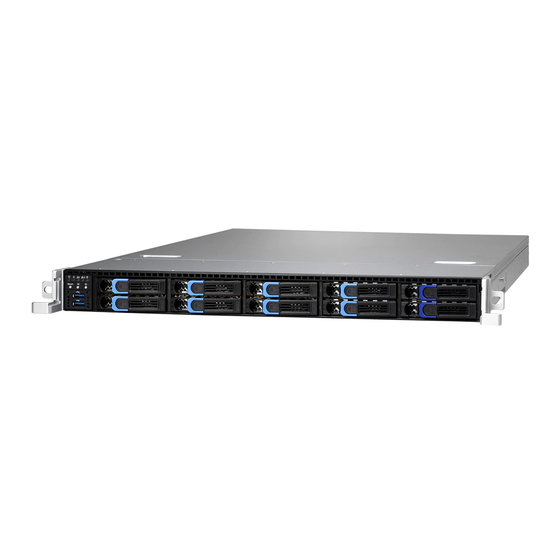
Hot-Swap SSDs/HDDs.GT62F-B5630 uses rack-mountable 1U chassis featuring a robust structure and a solid mechanical enclosure. All of this provides GT62F-B5630 the power and flexibility to meet the needs of nearly any server application. Product Models The system board within the Tyan MicroServer blade contains different processors and chipsets, which are defined by the following models: ... - Page 15 Features B5630G62FV6E4HR Specifications Form Factor 1U Rackmount Chassis Model GT62F 24.6" x 17.2" x 1.72" (625.4 x 436 x Dimension (D x W x H) 43.6mm) System Motherboard S5630GMRE Gross Weight 20 kg (44 lbs) Net weight 10.5kg (23.5 lbs) Buttons (1) PWR, (1) RST, (1) ID Front Panel...
- Page 16 Memory channel 6 Channels Memory voltage 1.2V PCI-E (1) PCI-E Gen3 x16 slots Expansion Slots (1) PCI-E Gen3 x8 OCP 2.0 slots Others: (con.A+con.B+con.C) Port Q'ty (1) PHY Realtek RTL8211E Connector (2) Mini-SAS HD (8-ports) Controller Intel C621 SATA Speed 6.0 Gb/s RAID RAID 0/1/10/5 (Intel RSTe)
- Page 17 90%, non-condensing at 35° C Humidity RoHS RoHS 6/6 Compliant (1) Web User's manual, (1) Quick Manual Installation Guide Package Contains Installation CD (1) TYAN installation CD Barebone (1) GT62F-B5630 Barebone B5630G62FV2E8HR Specifications Form Factor 1U Rackmount Chassis Model GT62F System 24.6"...
- Page 18 LRDIMM/ 1,536GB RDIMM Capacity 3DS/LRDIMM 3DS *Follow latest Intel DDR4 Memory POR Memory channel 6 Channels Memory voltage 1.2V Pre-install TYAN M2091, PCI-E x16 1U riser card Riser Card (left) Expansion Slots (1) PCI-E Gen3 x8 OCP 2.0 slots Others: (con.A+con.B+con.C)
- Page 19 Port Q'ty (1) PHY Realtek RTL8211E Connector (2) Mini-SAS HD (8-ports) Controller Intel C621 SATA Speed 6.0 Gb/s RAID RAID 0/1/10/5 (Intel RSTe) (2) PCI-E x8 SFF-8611 OCuLink connectors for (4) NVMe ports, NVMe (1) M2093 w/ (2) PCI-E x8 Storage SFF-8611 OCuLink connectors for (4) NVMe ports...
- Page 20 Humidity RoHS RoHS 6/6 Compliant (1) Web User's manual, (1) Quick Manual Installation Guide Package Contains Installation CD (1) TYAN installation CD Barebone (1) GT62F-B5630 Barebone B5630G62FV10HR Specifications Form Factor 1U Rackmount Chassis Model GT62F 24.6" x 17.2" x 1.72" (625.4 x 436 x Dimension (D x W x H) 43.6mm)
- Page 21 IPMI/Warning I/O Ports (2) USB 3.0 port Type / Q'ty 2.5" Hot-Swap SSD/HDD/ (10) HDD backplane SAS, SATA 6.0Gb/s, NVMe External Drive Bay support Supported HDD (10) SATA 6Gb/s Interface System Cooling (5) 4cm fans Configuration Type ERPS 1U Input Range AC 100-240V/8A Frequency 50-60 Hertz...
- Page 22 RAID RAID 0/1/10/5 (Intel RSTe) (2) PCI-E x8 SFF-8611 NVMe OCuLink connectors for (4) NVMe ports (2) 8-pin Connector SATA/SATA-DOM, (1) Mini-SAS HD (4-ports) sSATA Controller Intel C621 Speed 6.0 Gb/s RAID RAID 0/1/10/5 (Intel RSTe) Connector type D-Sub 15-pin Graphic Resolution Up to 1920x1200...
- Page 23 (1) Web User's manual, (1) Quick Manual Installation Guide Package Contains Installation CD (1) TYAN installation CD Barebone (1) GT62F-B5630 Barebone NOTE: 1. The specifications are subject to change without prior notice. 2. Please visit our website for the latest specifications.
-
Page 24: Standard Parts List
Standard Parts List This section describes GT62F-B5630 package contents and accessories. Open the box carefully and ensure that all components are present and undamaged. The product should arrive packaged as illustrated below. 1.3.1 Box Contents GT62F-B5630 (B5630G62FV6E4HR) Box Content ... -
Page 25: Accessories
(1) M2091/Riser Board (pre-installed) 1.3.2 Accessories If any items are missing or appear damaged, contract your retailer or browse to ® ’s website for service: http://www.tyan.com. TYAN GT62F-B5630 Accessory Kit (1) CPU Clip Narrow Non-Fabric CPU Carrier+COVER ... - Page 26 HDD Sequence (B5630G62FV2E8HR) HDD1 (NVMe1) HDD3(NVMe3) HDD5(NVMe5) HDD7(NVMe7) HDD9 HDD0 (NVMe0) HDD2(NVMe2) HDD4(NVMe4) HDD6(NVMe6) HDD8 HDD Sequence (B5630G62FV6E4HR) HDD1 (NVMe1) HDD3 HDD5 HDD7 HDD9 (NVMe3) HDD0 (NVMe0) HDD2 HDD4 HDD6 HDD8 (NVMe2) HDD Sequence (B5630G62FV10HR) HDD1 HDD3 HDD5 HDD7 HDD9 HDD0 HDD2 HDD4...
-
Page 27: System Rear View
LAN1 Access Green Access / Green Blinking Linking / Green Solid On Link Green Off Link / Green Off Off Link LAN2 Access Green Access / Green Blinking Linking / Green Solid On Link Green Off Link / Green Off Off Link 1.4.2 System Rear View... -
Page 28: Internal View
Solid Green Link 10 Mbps Blinking Green Active Solid Green Solid Green Link 100 Mbps Blinking Green Solid Green Active Solid Green Solid Amber Link 1000 Mbps Blinking Green Solid Amber (1Gbps) Active 1.4.4 Internal View B5630G62FV2E8HR Description M1716G75-FPB Front Panel Board (10) 2.5”... - Page 29 PCIE 80P OCULINK Connector(J21) PCIE 80P OCULINK Connector(J20) PCIE 3.0 x16 slot (J5)
-
Page 30: Chapter 2: Setting Up
Chapter 2: Setting Up 2.0.1 Before you Begin This chapter explains how to install the CPUs, CPU heatsinks, memory modules, and hard drives. Instructions on inserting add on cards are also given. 2.0.2 Work Area Make sure you have a stable, clean working environment. Dust and dirt can get into components and cause malfunctions. -
Page 31: Installing Motherboard Components
Working on a system that is connected to a power supply can be extremely dangerous. Follow the guidelines below to avoid damage to GT62F-B5630 or injury to yourself. Ground yourself properly before removing the top cover of the system. -
Page 32: Removing The Chassis Cover
2.1.1 Removing the Chassis Cover Follow these instructions to remove GT62F-B5630 chassis cover. Remove the side screw on the chassis cover as in the small diagram. Loosen the Thumb screw on the back side of the chassis as in the small diagram in a counterclockwise direction. -
Page 33: Installing The Cpu And Heat Sink
2.1.3 Installing the CPU and Heat sink Follow the steps below on installing CPUs and CPU heat sinks. Locate the CPU socket. Remove the CPU protection cap. - Page 34 Put the Narrow-Fabric processor on the Carrier hook clips. Align and install the processor on the carrier. Carefully flip the heatsink. Then install the carrier assembly on the bottom of the heatsink and make sure Carrier hook clips is stuck in the heatsink.
-
Page 35: Installing The Memory
Align the heatsink on the CPU socket by the guide pins and make sure the gold arrow is located in the correct direction. Then place the heatsink onto the top of the CPU socket. To secure the heatsink, use a T30 Security Torx to tighten the screws in a sequential order (1->2 ->... - Page 36 Press the memory slot locking levers in the direction of the arrows as shown in the following illustration. 2. Align the memory module with the slot. When inserted properly, the memory slot locking levers lock automatically onto the indentations at the ends of the module.
-
Page 37: Installing Hard Drives
2.1.5 Installing Hard Drives The GT62F-B5630 supports (10) 2.5” Hard Drives. Follow these instructions to install a hard drive. - Page 38 2.5” Hard Disk Drive Located at the 2.5” HDD tray. Press the locking lever to release the 2.5”SSD/ HDD tray Pull out the 2.5”SSD/ HDD tray. Remove the 4 screws to detach HDD tray bracket.
-
Page 39: Installing The Add-On Card
Place a hard drive into the drive tray. Use four screws to secure the HDD. Reinsert the HDD tray into the chassis. Press the locking lever to lock the 2.5”SSD/ HDD tray 2.1.6 Installing the Add-On Card TheGT62F-B5630 has one preinstalled M2091 riser card. - Page 40 You can install an Add-On card into the expansion slot which is available with riser card. The following instructions are for Add-On card installation. You may refer to the procedures below for the installation. 1. Remove the screw of PCI-E bracket and lift up the bracket. 2.
-
Page 41: Rack Mounting
4. Reinstall the riser bracket to the chassis. Rack Mounting... - Page 42 Mounting Ears (including screws) x 2 Screws Kit x 1 Mounting Brackets x 4 Installing the Server in a Rack Follow these instructions to mount the TYAN GT62F-B5630 into an industry standard 19" rack. Screws List Screw Size Quantity...
-
Page 43: Installing The Server In A Rack
2.2.1 Installing the Server in a Rack Follow these instructions to mount the TYANGT62F-B5630 into an industry standard 19" rack. NOTE: Before mounting the TYANGT62F-B5630 in a rack, ensure that all internal components have been installed and that the unit has been fully tested. However, to make the installation easier, we suggest that you remove all HDD trays before you insert the chassis into the rack. - Page 44 Pull the inner sliding rail forward to secure it to the chassis. And secure the inner rail to the chassis with 2 screws. Screw the mounting ear to each side of TYAN GT62F as shown using two screws of #6-32 L5.3 (D) from the supplied screws kit.
-
Page 45: Installing The Outer Rails To The Rack
2.2.3 Installing the Outer Rails to the Rack Secure the outer rail to the rack using (8) M5+washer (A) screws for each side. 2.2.4 Rack mounting the Server Lift the unit and then insert the inner slide rails into the middle rails. - Page 46 Press the white button in the direction of the arrow to push the whole system into the rack.
- Page 47 Secure the mounting ears of chassis to the rack with 2 M5-15L(C) screws.
-
Page 48: Chapter 3: Replacing Pre-Installed Components
Chapter 3: Replacing Pre-Installed Components Introduction This chapter explains how to replace the pre-installed components, including the S5630GMRE Motherboard, M1716G75-FPB Front Panel Board, M1274G62B-BP12E-10-2/ M1286G62-BP12E-10 Backplane, M2091/M2093 Riser Card, System Fan and Power Supply etc. Disassembly Flowchart The following flowchart outlines the disassembly procedure. Removing the Cover... -
Page 49: Replacing The Riser Card
Before replacing any parts you must remove the chassis cover. Follow Chapter 2.1.1 to remove the cover of GT62F-B5630. Replacing the Riser Card 1. TheGT62F-B5630 has preinstalled (1) M2091 riser cards. Release the 2 screw to lift the riser bracket from the chassis. -
Page 50: Replacing The Hdd Backplane
2. Disconnect all the fan cables and take out the fan. 3. Take out the rubbers to replace a new fan. Replacing the HDD Backplane GT62F-B5630 is equipment with two kinds of HDD Backplanes. Follow these instructions to replace the M1274G62B-BP12E-10-2/ M1286G62- BP12E -10... - Page 51 First pull the HDD trays slightly forwards to make the HDD BP Board easier to uninstall. Disconnect all the cables connected to the HDD Backplane. Remove the four screws securing the bracket and lift the bracket. Remove the eight screws securing the bracket to the HDD backplane.
-
Page 52: Hdd Backplane Features
3.6.1 HDD Backplane Features M1274G62B-BP12E-10-2 Front View... -
Page 53: Connector Definition
Rear View PCB Dimensions: 420.4x36.7x2 MM (4) SAS/SATA+ PCIe HDD Connectors (6) SAS/SATA HDD Connectors (4) MINI SAS HD Connector connect to MB (2) MINI SAS Connector connect to MB (2) SATA connector connect to MB Integrated I/O (1) 2*10 Pin FAN connector connect to MB (6) 8 Pin FAN connector connect to FAN (2+1) 4Pin power connector connect to MB... - Page 54 HDD0 SAS/SATA + PCIe HDD Connector HDD1 SAS/SATA + PCIe HDD Connector HDD8 SAS/SATA + PCIe HDD Connector HDD9 SAS/SATA + PCIe HDD Connector SAS/SATA HDD Connector HDD2 SAS/SATA HDD Connector HDD3 SAS/SATA HDD Connector HDD4 SAS/SATA HDD Connector HDD5 SAS/SATA HDD Connector HDD6 SAS/SATA HDD Connector...
-
Page 55: Connector Definition
Rear View 420.4*36.7*2mm PCB Dimensions: Thickness: 2mm Layer: 8 layers (10)HDD NVMe Connector (5)OCCulink Connector (6)FAN Connector (1)4X2pin Power Connector Integrated I/O (1)4Pin Power Connector (2)SGPIO Header(J12/J13) (1)JTAG Header (2)SATA Connector 3.6.3 Connector Definition HDD0/1/8/9: SAS/SATA + PCIe Connector Definition Definition SAS_TX_DP0... - Page 56 SAS_RX_DN0 SAS_RX_DP0 SAS_PRS_L PE_TX_DP1 PE_TX_DN1 PE_RX_DN1 PE_RX_DP1 PE_TX_DP2 PE_TX_DN2 PE_RX_DN2 PE_RX_DP2 VCC3_AUX PE_RST_N_R PE_CLK_DP PE_CLK_DN PE_TX_DP0 PE_TX_DN0 PE_RX_DN0 PE_RX_DP0 PE_TX_DP3 PE_TX_DN3 PE_RX_DN3 PE_RX_DP3 PE_SMB_CLK PE_SMB_DAT HD_DP_EN_N PE_WAKE_N DEV_SLP# IFDET# VDD_5_RUN VDD_5_RUN VDD_5_RUN HD_PRS_L HD_LED VDD_12_RUN VDD_12_RUN VDD_12_RUN GND1 GND2 PW1: Power Connector Definition Definition VDD_12V_RUN...
- Page 57 HD2_VDD5 VDD5 VDD5 HD2_PRS_L HD2_LED HD2_VDD12 VDD12 VDD12 GND1 GND2 SATA8/9: SATA Connector Definition Definition SAS_TX_DP8 SAS_TX_DN8 SAS_RX_DN8 SAS_RX_DP8 GND1 GND1 J29: 2*10 Pin FAN I/O Connector Definition Definition FAN_TACH1 FAN_TACH6 FAN_TACH2 FAN_TACH7 FAN_TACH3 FAN_TACH8 FAN_TACH4 FAN_TACH9 FAN_TACH5 FAN_TACH10 CON_PWM2 CON_PWM1 FAN_TACH11 BMC_3V3_DAT...
- Page 58 SAS_TX_DP3 SAS_TX_DN3 SAS_RX_DP0 SAS_RX_DN0 SAS_RX_DP1 SAS_RX_DN1 SMB2_DATA3 SAS_SIO_DOUT_A SAS_SIO_DIN_A SAS_RX_DP2 SAS_RX_DN2 SAS_RX_DP3 SAS_RX_DN3 J1: JTAG Connector Definition Definition TCK_A TDO_A VDD_3P3_RUN TMS_A TDI_A J2: SGPIO Connector Definition Definition SDATA IN SDATA OUT- SLOAD SCLOCK P3V3_AUX HD_ERROR_LED PW2: Power Connector Definition Definition VDD_12V_RUN VDD_5V_RUN...
- Page 59 GND4 GND16 PEAp2 PEBp2 PEAp2 PEBp2 GND5 GND17 PEAn3 PEBp3 PEAn3 PEBp3 GND6 GND18 GND7 GND19 PEAn4 PEBp4 PEAn4 PEBp4 GND8 GND20 PEAn5 PEBp5 PEAn5 PEBp5 GND9 GND21 GND10 GND22 PEAp6 PEBp6 PEAp6 PEBp6 GND11 GND23 PEAp7 PEBp7 PEAp7 PEBp7 GND12 GND24 J7: Front Panel Connector...
-
Page 60: Hdd Bp Board Led Definitions
3.6.4 HDD BP Board LED Definitions B5630G62FV6E4HR/ B5630G62FV10HR HDD Status Status LED Activity LED Color: Amber Color: Green No Driver Present or power disconnected Driver Present No Activity Access Activity Blinking... -
Page 61: Replacing The Front Panel Board
HDD Fail On Solid Identify (Locate the HDD) Blinking(1Hz) Rebuild Blinking(4Hz) B5630G62FV2E8HR HDD Status ODn0 ODn1 ODn2 Activity Status LED (Act) (Locate) (Fail) Color: Amber Color: Green Drive not Present Driver Activity Present Activity 1or 4Hz Blinking HDD Fail On Solid Identify (Locate the Blinking(1Hz) HDD) - Page 62 Disconnect the control cable and USB3.0 cable from the front panel board.
-
Page 63: Front Panel Board Features
Unscrew the front panel board from the front panel tray for a new one. Reinstall the Front Panel Board into the chassis following the steps in reverse. 3.7.1 Front Panel Board Features Front View... -
Page 64: Connector Definition
Rear View Form Factor 28 x 35.4 x 1.6 (mm), 4-layer PCB I/O: (2) USB3.0 Port LED Indicators: (1) HDD LED (1) Warning LED Specifications (2) LAN LED (1) Power/ID LED Switch: (1) Reset Button (1) ID Button (1) Power Button 3.7.2 Connector Definition Location... -
Page 65: Replacing The Power Supply
BMC_EVENT_LED Warning LED LAN1_LED LAN1 LED LAN2_LED LAN2 LED ID_PW_LED Power/ID LED USB3.0 Port USB3.0 Port Reset Button ID Button Power Button USB3.0 Connector Front Panel Control Board Connector Replacing the Power Supply To replace the power supply follow these instructions. Located at the power supply usage. -
Page 66: Replacing The Power Distribution Board
Free the power from the power socket. Replace a new power supply and reinsert it into the power socket following the above steps in reverse. Replacing the Power Distribution Board Please unplug the power cord before you follow these instructions to replace the Tiger PDB Redundant Control Board Power Distribution Board. -
Page 67: Front Panel Board Features
Unscrew the 4 screws from the power distribution board. 3.9.1 Front Panel Board Features Tiger PDB Redundant Control Board... -
Page 68: Connector Definitions
Form Factor 114.62mm (L) x 105.6mm (W) x 28mm (H) CON1 , CON2: Input connector CON3: Mini fit 24 pin power connector Specifications CON4 , CON5: HDD 4 pin power connector CON6: PMBus 5 pin CON7 , CON8 : Mini fit 8 pin 3.9.2 Connector Definitions CON1/CON2: Input connector / Pin assignment... - Page 69 +12V +12V SGND SGND +12VRS+ +12VRS- +12VLS SMBAlert PMBus SDA PMBus SCL PSKILL PSON DC_GOOD A1 (SMBus address) +5Vsb +5Vsb SGND(PRESENT) A0 (SMBus address) B/P SIG SGND B/P FAIL +5Vsb +5Vsb CON3: Mini fit 24 pin Output connector / Pin assignment Definition Definition +3.3V...
- Page 70 SGND PS ON SGND SGND SGND SGND CON6: PMBus 5 pin Definition Definition SMBAlert SGND CON7/CON8: Mini fit 8 pin Definition Definition SGND SGND SGND SGND +12V +12V +12V +12V...
-
Page 71: Replacing The Motherboard
3.10 Replacing the Motherboard After removing all of the aforementioned cables, follow these instructions to remove the motherboard from the chassis. 1. Disconnect SATA and USB cables. 2. Disconnect the power cable and PSMI Cable. 3. Disconnect the front panel cable and fan control cable. - Page 72 NOTE...
-
Page 73: Appendix I: Cable Connection Tables
Appendix I: Cable Connection Tables 1. System Fan Connector System Fan to M1274 Backplane (BP) Board M1274G62B-BP12E-10-2 System Fan Connect to M1286G62F-BP12E-10 → Fan1 FAN1 → Fan2 FAN2 → Fan3 FAN3 → Fan4 FAN4 → Fan5 FAN5 2. FP Control Cable and USB Cable M1716G75-FPB Control Board to S5630 MB M1716G75-FPB Connect to... - Page 74 (FOR B5630G62FV6E4HR) M1274 Backplane (BP) Board to S5630 MB M1274G62B-BP1 Cable Connect to S5630GMRE 2E-10-2 Mini-SAS HD → SATA0_3 sSATA 0_3 Cable Mini-SAS HD → SATA4_7 SATA 0_3 Cable NVME0 Oculink Cable → (to Mini-SAS HD) /NVME1 NVME2 Oculink Cable →...
-
Page 75: Power Cables
CON6 PSIMI1 TD15-0128-02 PDB to M1274 Backplane (BP) Board M1274G62B-BP12 TD15-0128-02 Connect to E-10-2 → CON5 B4P CABLE → CON4 B4P CABLE 5. Chassis intrusion Cables Chassis to S5630 MB Cable Chassis Connect to S5630GMRE → GT62F-B5630 INTRUDER_DH1 Intrusion Cable... -
Page 76: Appendix Ii: Fan And Temp Sensors
Appendix II: Fan and Temp Sensors This section aims to help readers identify the locations of some specific FAN and Temp Sensors on the motherboard. A table of BIOS Temp sensor name explanation is also included for readers’ reference. NOTE: The red dot indicates the sensor. - Page 77 BIOS Temp Sensor Name Explanation:...
- Page 78 P0_DTS_Temp Temperature of the CPU0 Digital Temperature Sensor P0_PECI_Value Temperature of the CPU0 Platform Environment Control Interface P0_MC0_DIM_CH_A The highest temperature of CPU0 MC0 DIM channel A slot P0_MC0_DIM_CH_B The highest temperature of CPU0 MC0 DIM channel B slot P0_MC0_DIM_CH_C The highest temperature of CPU0 MC0 DIM channel C slot P0_MC1_DIM_CH_D The highest temperature of CPU0 MC1 DIM channel D slot...
-
Page 79: Appendix Iii: Fru Parts Table
Appendix III: FRU Parts Table GT62F-B5630 FRU Parts Item Model Number Part Number Picture Description TF-CABLE ASSY;SAS INTERNAL,SBU,34 AWG,450 FRU-CS-0810 422T57200002 mm,OCuLink 8X CABLE, OCuLink 8X 80P/SHORT MINI-SAS HD 36P*2,GT62F-B5630 TF-CABLE ASSY;SASINTERNAL,SBU,30 AWG,800 FRU-CS-0770 422T57000003 mm,OCuLink 8X CABLE, OCuLink 8X 80P/SHORT MINI-SAS HD 36P*2,GT75B-B7102 TF-CABLE ASSY;SASINTERNAL,SBU,... - Page 80 NOTE http://www.tyan.com...
-
Page 81: Appendix Iv: Technical Support
MITAC serves multiple market segments with the industry’s most competitive services to support them. Please feel free to contact us directly for this service at tech-support@tyan.com Help Resources: 1. See the POST codes section of this manual. - Page 82 (RMA) number. The RMA number should be prominently displayed on the outside of the shipping carton and the package should be mailed prepaid. TYAN will pay to have the board shipped back to you. ® GT62F-B5630 Service Engineer’s Manual V1.0b TYAN Document No.: D2405 - 100...
Need help?
Do you have a question about the GT62F-B5630 and is the answer not in the manual?
Questions and answers