Table of Contents
Advertisement
Quick Links
Advertisement
Table of Contents

Related Manuals for TYAN GT90-B7113


Summary of Contents for TYAN GT90-B7113
- Page 1 GT90-B7113 Service Engineer’s Manual http://www.tyan.com...
- Page 2 http://www.tyan.com...
- Page 3 MITAC assumes no liability whatsoever, and ® disclaims any express or implied warranty, relating to sale and/or use of TYAN products including liability or warranties relating to fitness for a particular purpose or merchantability. MITAC retains the right to make changes to produce descriptions and/or specifications at any time, without notice.
- Page 4 This Class A digital apparatus complies with Canadian ICES-003. Cet appareil numérique de la Classe A est conforme à la norme NMB-003 du Canada. Notice for Europe (CE Mark) ● This product is in conformity with the Council Directive 2014/30/EU and 2014/35/EU. http://www.tyan.com...
- Page 5 Replace only with the same or equivalent type recommended by manufacturer. Dispose of used battery according to manufacturer instructions and in accordance with your local regulations. VCCI-A ● この装置は、クラスA機器です。この装置を住宅環境で使用すると電波妨害を引き 起こすことがあります。この場合には使用者が適切な対策を講ずるよう要求される VCCI-A ことがあります。 Safety: IEC/EN 60950-1 ● This equipment is compliant with CB/LVD of Safety: IEC/EN 60950-1. http://www.tyan.com...
- Page 6 About this Manual This manual is intended for trained service technician/personnel with hardware knowledge of personal computers. It is aimed to provide you with instructions on installing your TYAN GT90-B7113. How this guide is organized This guide contains the following parts:...
- Page 7 Safety and Compliance Information Before installing and using TYAN GT90-B7113, take note of the following precautions: ·Read all instructions carefully. ·Do not place the unit on an unstable surface, cart, or stand. ·Do not block the slots and opening on the unit, which are provided for ventilation.
- Page 8 You must become familiar with the safety information in this guide before you install, operate, or service TYAN products. Symbols on Equipment Caution. This symbol indicates a potential hazard.
- Page 9 · Make sure the stabilizing feet are attached to the rack if it is a single-rack installation. · Make sure racks are coupled together if it is a multiple-rack installation. · Make sure the rack is level and stable before installing an appliance in the rack. http://www.tyan.com...
- Page 10 · In all European electrical environments, you must ground the Green/Yellow tab on the power cord. If you do not ground the Green/Yellow tab, it can cause an electrical shock due to high leakage currents. http://www.tyan.com...
- Page 11 TYAN, your authorized TYAN partner, or their agents. Equipment Modifications · Do not make mechanical modifications to the system. TYAN is not responsible for the regulatory compliance of TYAN equipment that has been modified.
- Page 12 – The product does not operate normally when you follow the operating instructions. · Retain all screws or other fasteners when removing access cover(s). Upon completion of accessing inside the product, refasten access cover with original screws or fasteners. http://www.tyan.com...
-
Page 13: Table Of Contents
Table of Contents Chapter 1: Overview............... 17 About the TYAN GT90-B7113 ..........17 Product Models ............... 17 Features .................. 18 Standard Parts List ..............25 1.4.1 Box Contents and Accessories ........25 About the Product ..............26 1.5.1 System Front View ............26 1.5.2... - Page 14 AST2500 Super IO Configuration ........137 5.3.9 S5 RTC Wake Settings ..........139 5.3.10 Serial Port Console Redirection ........140 5.3.11 Option ROM Dispatch Policy ......... 146 5.3.12 PCI Subsystem Settings ..........147 5.3.13 USB Configuration ............148 5.3.14 CSM Configuration ............150 http://www.tyan.com...
- Page 15 AMIBIOS Post Code (Aptio) ..........222 Appendix I: How to recover UEFI BIOS ........231 Appendix II: Cable Connection Tables ........233 Appendix III: Fan and Temp Sensors ......... 235 Appendix IV: FRU Parts Table ............. 241 Appendix V: Technical Support ..........243 http://www.tyan.com...
- Page 16 NOTE http://www.tyan.com...
-
Page 17: Chapter 1: Overview
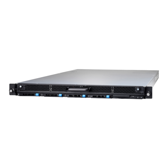
TYAN ® also offers the GT90-B7113 in a version that can support up to twelve (12) internal hot-swappable 3.5” SAS/SATA HDD and four (4) external hot-swappable 2.5” 7mm SATA/NVMe SSD/HDD. The GT90-B7113 uses TYAN’s latest chassis featuring a robust structure and a solid mechanical enclosure. -
Page 18: Features
Features TYAN GT90-B7113 (B7113G90V12E4HR) Form Factor 1U Rackmount Chassis Model GT90 35.43" x 19.21" x 1.71" Dimension (D x W x H) (900 x 448 x 43.5mm) System Motherboard Name S7113GMRE # Motherboard # The motherboard not sold Notification separately Gross Weight 32 kg (70.5 lbs) - Page 19 / Intel Optane DC Notification: Persistent Memory Module (DCPMM) only supported with specific 2nd Gen Intel Xeon Scalable Processor (codename: Cascade Lake). Please contact Tyan Technical Support for more detail. (1) PCI-E Gen3 x16 OCP 2.0 slot Expansion Slots Others: (conn.A+conn.B) (1) PCI-E Gen3 x8 storage mezz.
- Page 20 Class A CE (DoC) Class A Regulation CB/LVD Class A VCCI Class A Operating Temp. 10° C ~ 35° C (50° F~ 95° F) Operating Environment Non-operating Temp. - 40° C ~ 70° C (-40° F ~ 158° F) http://www.tyan.com...
- Page 21 In/Non-operating 90%, non-condensing at 35° C Humidity RoHS RoHS 6/6 Compliant Barebone (1) GT90-B7113 Barebone Package Contains Manual (1) Quick Installation Guide GT90-B7113 (B7113G90U12E4HR) Form Factor 1U Rackmount Chassis Model GT90 35.43" x 19.21" x 1.71" Dimension (D x W x H) (900 x 448 x 43.5mm)
- Page 22 Notification: Persistent Memory Module (DCPMM) only supported with specific 2nd Gen Intel Xeon Scalable Processor (codename: Cascade Lake). Please contact Tyan Technical Support for more detail. Pre-install TYAN Riser (1) M7113-R8-1F # riser card for (1) Card PCI-E Gen3 x8 slot (right)
- Page 23 LSI SAS3416 IOC on (1) Controller Tyan M7113-3416-16I Storage Mezz. Card Speed 12Gb/s RAID 0/1/10 (LSI RAID Integrated RAID) Connector (1) SATA-DOM Controller Intel C621 sSATA Speed 6Gb/s RAID RAID 0/1/10/5 (Intel RSTe) Connector (4) SFF-8654 for (4) NVMe NVMe...
- Page 24 In/Non-operating 90%, non-condensing at 35° C Humidity RoHS RoHS 6/6 Compliant Barebone (1) GT90-B7113 Barebone Package Contains Manual (1) Quick Installation Guide NOTE: 1. The specifications are subject to change without prior notice. 2. Please visit our Web site for the latest specifications.
-
Page 25: Standard Parts List
Standard Parts List This section describes GT90-B7113 package contents and accessories. Open the box carefully and ensure that all components are present and undamaged. The product should arrive packaged as illustrated below. 1.4.1 Box Contents and Accessories If any items are missing or appear damaged, contact your retailer or browse to TYAN’s website for service:... -
Page 26: About The Product
(4) hot-swap external 2.5” 7mm NVMe SSD Description Front Panel Warning LED Front Panel HDD LED ID Button w/ blue LED Power Button w/ green LED NVMe#00/HDD#00 NVMe#01/HDD#01 NVMe#02/HDD#02 NVMe#03/HDD#03 NOTE: #5~#8 are hot swap external 2.5” 7mm SATA/NVMe HDD trays. http://www.tyan.com... -
Page 27: Front Panel And Hdd Led Indications
Solid On Don’t care Identify Blinking(1Hz) Don’t care Rebuild Blinking(4Hz) Don’t care Front Panel LED Indications (B7113G90V12E4HR) Color Behavior Green Normal/Off Active/Blinking Warning Normal/Off Warning/Solid On Front Panel LED Indications (B7113G90U12E4HR) Color Behavior Green Normal/On Active/Blinking Warning Normal/Off Warning/Solid On http://www.tyan.com... -
Page 28: System Rear View
1.5.3 System Rear View Description PSU1 PSU0 ID Button w/ blue LED OCP Card Area IPMI LAN USB3.0 Ports VGA Port Serial Port http://www.tyan.com... -
Page 29: Psu And Lan Led Indications
Green Solid On Green Solid On 100 Mbps Active Green Blinking Green Solid On Link Green Solid On Amber Solid On 1000 Mbps (1Gbps) Active Green Blinking Amber Solid On NOTE: “Left” and “Right” are viewed from the rear panel. http://www.tyan.com... -
Page 30: System Top View
1.5.5 System Top View Description Description FAN1 FAN6 FAN2 Cable Cover FAN3 PSU1 FAN4 PSU0 FAN5 Storage Card (M7113-3416-16I) http://www.tyan.com... - Page 31 Description Description FAN1 FAN6 FAN2 Cable Cover FAN3 PSU1 FAN4 PSU0 FAN5 http://www.tyan.com...
-
Page 32: Chassis Dimensions
1.5.6 Chassis Dimensions http://www.tyan.com... -
Page 33: Chapter 2: Setting Up
To avoid damaging the motherboard and associated components, use torque force within the range kgf/cm (4.35 ~ 6.09 lb/in) on each mounting screw for motherboard installation. Do not apply power to the board if it has been damaged. 2.0.4 Precautions http://www.tyan.com... - Page 34 Working on a system that is connected to a power supply can be extremely dangerous. Follow the guidelines below to avoid damage to GT90-B7113 or injury to yourself. Ground yourself properly before removing the top cover of the ...
-
Page 35: Installing Motherboard Components
This section describes how to install components on to the motherboard, including CPUs, memory modules and Add-on cards. 2.1.1 Removing the Chassis Cover Follow these instructions to remove the GT90-B7113 chassis cover. Loosen the thumb screw on the rear top cover. 2. Slide to lift up the rear top cover. http://www.tyan.com... - Page 36 3. Unscrew the front top cover. 4. Press the tabs on both sides to lift up the front top cover from the chassis. http://www.tyan.com...
- Page 37 http://www.tyan.com...
-
Page 38: Replacing The Chassis Cover
2.1.2 Replacing the Chassis Cover Follow these instructions to replace the GT90-B7113 chassis cover. Put down the front top cover and slide it forwards. Secure the front top cover by tightening four flat screws and two thumbscrews. http://www.tyan.com... - Page 39 Put down the rear cover and slide it backwards. Secure the rear top cover by tightening the thumbscrew. http://www.tyan.com...
-
Page 40: Installing The Cpu And Heat Sink
Carefully flip the heatsink. Then install the carrier assembly on the bottom of the heatsink and make sure the gold arrow is located in the correct direction. Locate the CPU socket’s guide pin. Always start with CPU0 first. Remove the CPU Socket protection cap. http://www.tyan.com... - Page 41 Then place the heatsink onto the top of the CPU socket. To secure the heatsink, use a T30 Security Torx to tighten the screws in a sequential order (1234). http://www.tyan.com...
- Page 42 NOTE: When disassembling the heatsink, loosen the screws in reverse order (4321). Repeat the procedures described earlier to install the second processor and heatsink. http://www.tyan.com...
-
Page 43: Installing The Memory
Press the memory slot locking levers in the direction of the arrows as shown in the following illustration. Align the memory module with the slot. When inserted properly, the memory slot locking levers lock automatically onto the indentations at the ends of the module. http://www.tyan.com... - Page 44 2. Use paired memory installation for max performance. 3. Populate the same DIMM type in each channel, specifically - Use the same DIMM size - Use the same # of ranks per DIMM 4. Always install with CPU0 Socket first. http://www.tyan.com...
- Page 45 √ √ √ √ P1_MC0_DIM_CH_B1 √ √ √ √ √ √ √ √ P1_MC0_DIM_CH_B0 P1_MC0_DIM_CH_C0 √ √ √ √ P1_MC1_DIM_CH_D0 √ √ √ √ √ √ √ P1_MC1_DIM_CH_E1 √ √ P1_MC1_DIM_CH_E0 √ √ √ √ √ √ √ P1_MC1_DIM_CH_F0 http://www.tyan.com...
-
Page 46: Installing The Expansion Card
The Rear I/O Area supports both RJ45 and SFP Bracket. Follow these instructions to replace the Rear I/O Bracket (RJ45 or SFP) and install the Expansion Card. Unscrew the Rear IO RJ45 Bracket. Remove the RJ45 Bracket and replace with the SFP Bracket. Screw the SFP I/O Bracket to the chassis. http://www.tyan.com... - Page 47 Insert the expansion card onto the OCP riser card slot and use 4 screws to secure it to the chassis. http://www.tyan.com...
-
Page 48: Installing 2.5" Hard Drives
2.1.6 Installing 2.5” Hard Drives The GT90-B7113 supports four 2.5” SSDs/HDDs. Follow these instructions to install a hard drive. Press the tab to release the lever. Pull the HDD tray away from the chassis. Place a HDD/SSD into the drive tray. - Page 49 Reinsert the HDD tray into the HDD cage. Close the lever. http://www.tyan.com...
-
Page 50: Installing 3.5" Hard Drives
2.1.7 Installing 3.5” Hard Drives The GT90-B7113 supports twelve 3.5” HDDs. Follow these instructions to install a hard drive. Push the tabs on both sides to pull open the slide-out HDD tray. Push the tab to release the 3.5” HDD carrier. Pull open the lever to take out the 3.5”... - Page 51 Place a 3.5” HDD into the HDD carrier. Reinsert the HDD carrier into the chassis. Close the lever. http://www.tyan.com...
-
Page 52: Rack Mounting
Mounting Ears x 2 Screw Sacks x 2 2.2.1 Installing the Server in a Rack Follow these instructions to mount the GT90-B7113 into an industry standard 19” rack. Note: Before mounting GT90-B7113 in a rack, ensure that all internal components have been installed and that the unit has been fully tested. -
Page 53: Installing Slide Rails To The Rack
2.2.2 Installing Slide Rails to the Rack Take out the rails from the accessory kit. Attach the rails to the rack. Please note that the square stud must be fully attached inside the square hole on the rack rail. http://www.tyan.com... - Page 54 Repeat the same procedures for the other side. http://www.tyan.com...
-
Page 55: Rack Mounting The Server
Read the Warning Label on the chassis top cover before you install the chassis. Install the chassis. Must be done with at least 2 people. Properly place the chassis directly on the rack and install. Fasten the chassis ear to the front surface of chassis. http://www.tyan.com... - Page 56 Take out the rack stopper pack from the Accessory Kit. Fasten the stopper R&L to the rear end of chassis by M5 screws. http://www.tyan.com...
-
Page 57: Removing The Server From Rack
2.2.4 Removing the Server from Rack Release the chassis ear by loosening the screw. Release the stopper R&L by loosening M5 screws. http://www.tyan.com... - Page 58 Pull out the chassis half way to the lock position. Caution: Remove the server from the rack carefully. Must be done with at least 2 people. Remove the slide rails from the rack. http://www.tyan.com...
-
Page 59: Chapter 3: Replacing Pre-Installed Components
Front Panel Board, M7113-R8-1F Riser Card, M1305G90-BP6E-4 HDD & M1304G90-BP12-4 HDD Backplane Board, M7113-HSBB High Speed Bridge Board, M7113-3416-16I Storage Mezz Card, M1624G90-T-PDB Power Distribution Board, System Fan and Power Supply etc. Disassembly Flowchart The following flowchart outlines the disassembly procedure. http://www.tyan.com... -
Page 60: Removing The Cover
Removing the Cover Follow Chapter 2.1.1 to remove the cover of GT90-B7113. Replacing the Power Supply To replace the power supply follow these instructions. Press the tab as shown to pull out the power supply module. Free the power from the power cage. -
Page 61: Replacing The Front Panel Board
Follow these instructions to replace the M1720G90-FPB Front Panel Board. Loosen three screws and disconnect the front panel cable. After replacing with a new Front Panel Board, follow the steps described earlier in reverse order to reinstall the front panel board module. http://www.tyan.com... -
Page 62: Front Panel Board Features
3.5.1 Front Panel Board Features M1720G90-FPB Front Panel Board Form Factor 38.8x9.7mm Specifications (1) Pin Header Connector (FPIO_1) Color State Description BMC fail LED BMC fail HDD Power/Access LED Green SATA/SAS HDD ready http://www.tyan.com... -
Page 63: Replacing The Hdd Backplane Board
. M1304G90-BP12-4 HDD Follow these instructions to replace the M1304G90-BP12-4 HDD Backplane Board. Push the tab to release the 3.5” HDD carrier. Pull open the lever to take out the 3.5” HDD carrier. Remove all four 3.5” HDD carriers. http://www.tyan.com... - Page 64 HDD Backplane Board Bracket to lift it up. After replacing with a new M1304G90-BP12-4 HDD Backplane Board, follow the procedures described earlier in reverse order to reinsert the HDD Backplane Board Bracket and 3.5” HDD carriers into the chassis. http://www.tyan.com...
- Page 65 HDD Backplane Board. Unscrew the HDD Backplane Board and disconnect all cables connected to the HDD Backplane Board for replacement. B7113G90V12E4HR B7113G90U12E4HR Follow the procedures described earlier in reverse order to reinstall the M1305G90-BP6E-4 HDD Backplane Board into the chassis. http://www.tyan.com...
-
Page 66: Hdd Bp Board Features
Golden Finger (Mini PCIe) Input (J1) Integrated I/O SATA HDD Output (HDD0~HDD3) b. M1305G90-BP6E-4 M1305G90-BP6E-4 HDD Backplane Board Form Factor 303*40.1mm Oculink Connector x4 for NVMe (NVME0~NVME3) Integrated I/O Oculink Connector x1 for SATA (SATA) NVMe/SATA HDD Connector x4 (HDD0~HDD3) http://www.tyan.com... -
Page 67: Connector Definitions
Oculink Connector for SATA NVME0 Oculink Connector for NVMe NVME1 Oculink Connector for NVMe NVME2 Oculink Connector for NVMe NVME3 Oculink Connector for NVMe HDD0 NVMe/SATA HDD Connector HDD1 NVMe/SATA HDD Connector HDD2 NVMe/SATA HDD Connector HDD3 NVMe/SATA HDD Connector http://www.tyan.com... -
Page 68: Replacing Power Distribution Board
Replacing Power Distribution Board Follow these instructions to replace the M1624G90-T-PDB Power Distribution Board. Pull the power supply modules slightly away from the chassis. Unscrew to lift up the cable cover. http://www.tyan.com... - Page 69 Disconnect all cables connect to the Power Distribution Board. Unscrew to replace the M1624G90-T-PDB Power Distribution Board. Follow the steps described earlier in reverse order to reinstall the power distribution board into the chassis. http://www.tyan.com...
-
Page 70: Power Distribution Board Features
Power supply link connector (J2 & J3) PDB board for Motherboard main power in (PWR1) Specifications PDB board for CPU 12V power in (PW3 & PW2) PDB board for M7113-HSBB 12V power in (PW4) PDB board and Motherboard link Header (J4) http://www.tyan.com... -
Page 71: Connector Definitions
Definition J2 & J3 Power supply link connector PDB board and Motherboard link Header PWR1 PDB board for Motherboard main power in PW3 & PW2 PDB board for CPU 12V power in PDB board for M7113-HSBB 12V power in http://www.tyan.com... -
Page 72: Replacing The Riser Card
Replacing the Riser Card Follow these instructions to replace the M7113-R8-1F Riser Card. Disconnect all cables connected to the M7113-3416-16I Storage Mezz card. Unscrew the Storage Mezz card to lift it up. Unscrew the Riser Card Bracket to lift it up. http://www.tyan.com... - Page 73 Unscrew to replace a new riser card. Follow the steps described earlier in reverse order to reinstall the riser card bracket. http://www.tyan.com...
-
Page 74: Riser Card Feature
3.8.1 Riser card Feature M7113-R8-1F Riser Card 76.8 x 30.6 mm Form Factor 80-pin Mini PCIE x8 Golden Finger (GF1) compatible with Motherboard Mini PCIE Slot (J11) Specification PCIE x8 Slot (J1) http://www.tyan.com... -
Page 75: Replacing The Storage Mezz Card
M7113-3416-16I Storage Mezz Card. Disconnect all cables connected to the M7113-3416-16I Storage Mezz card. Unscrew the Storage Mezz card to lift it up for replacement. Follow the steps described earlier in reverse order to reinstall the Storage Mezz Card. http://www.tyan.com... -
Page 76: Storage Mezz Card Feature
3.9.1 Storage Mezz Card Feature M7113-3416-16I Storage Mezz Card 113x102mm Form Factor LSI3416 chip SlimSAS x 3 Specification OCULink x1 http://www.tyan.com... -
Page 77: 3.10 Replacing The Fan
3.10 Replacing the Fan Follow these instructions to replace the fan module. Disconnect the fan cable. Lift up the fan module for replacement. Place the new fan into the chassis and reconnect the fan cable. http://www.tyan.com... -
Page 78: 3.11 Replacing The Motherboard
3.11 Replacing the Motherboard After removing all of the aforementioned components, follow these instructions to remove the motherboard from the chassis. Disconnect all cables. Unscrew the motherboard to lift it up for replacement. http://www.tyan.com... - Page 79 http://www.tyan.com...
- Page 80 NOTE http://www.tyan.com...
-
Page 81: Chapter 4: Motherboard Information
Caution! To avoid damaging the motherboard and associated components, use torque force within the range kgf/cm (4.35 ~ 6.09 lb/in) on each mounting screw for motherboard installation. Do not apply power to the board if it has been damaged. http://www.tyan.com... -
Page 82: Board Image
Board Image S7113 This picture is representative of the latest board revision available at the time of publishing. The board you receive may not look exactly like the above picture. http://www.tyan.com... -
Page 83: Block Diagram
Block Diagram S7113 Block Diagram http://www.tyan.com... -
Page 84: Motherboard Mechanical Drawing
Motherboard Mechanical Drawing http://www.tyan.com... -
Page 85: Board Parts, Jumpers And Connectors
The board you receive may not look exactly like the above diagram. The DIMM slot numbers shown above can be used as a reference when reviewing the DIMM population guidelines shown later in the manual. For the latest board revision, please visit our web site at http://www.tyan.com. http://www.tyan.com... - Page 86 ME Recovery Mode Jumper (J113) Slots MINI PCIE Slots 1 OCP 2.0 Connector B (J149) (for PCIE RISER x 8) (J11) OCP 2.0 Connector A (J28) Jumper Legend OPEN - Jumper OFF Without jumper cover CLOSED - Jumper ON With jumper cover http://www.tyan.com...
- Page 87 J146: SYSFAN 5&11 J121: Chassis Intrusion Header Signal INTRUSION_N open FPIO_1: Front Panel Header Signal Signal VCC3 VCC3 PW_LED ID_LED_PW PW_LED_N ID_LED_N HDD_LED BMC_HW_FAULT_N HDD_ACT_LED_N BMC_SYS_FAULT_N PWR_BTN_N IDLED_BTN_N SYS_AIR_INLET J147: PSMI and Power Connector Signal Signal PSMI_5V_SMBCLK PSMI_BMC_ALERT_N PSMI_5V_SMBDATA http://www.tyan.com...
- Page 88 PSU_ALERT_N ATX_VCC12_PG ATX_PS_ON_N VCC3 http://www.tyan.com...
- Page 89 PIN Define SATA_TXP SATA_TXN Connects to the Serial ATA ready drives via the SATA_RXN Serial ATA cable. SATA_RXP VCC5 VCC5 J113: ME Recovery Mode Jumper Pin 1-2 Closed: Normal Mode (Default) Pin 2-3 Closed: ME In Force Update Mode http://www.tyan.com...
- Page 90 5. Reconnect power connectors to the motherboard and power on system. Clear CMOS PWR1: 12-pin Main Power Connector Signal Signal VCC12_IN VCC12_IN VCC12_IN VCC12_IN VCC12_IN VCC5_SB PW1/PW2: 8-pin ATX Power Connector Signal Signal VCC12_IN VCC12_IN VCC12_IN VCC12_IN PWR3: 8-pin ATX Power Connector Signal Signal VCC12_IN VCC12_IN VCC12_IN VCC12_IN http://www.tyan.com...
-
Page 91: Thermal Interface Material
CPU lid (applying too much will actually reduce the cooling). NOTE: Always check with the manufacturer of the heat sink & processor to ensure that the thermal interface material is compatible with the processor and meets the manufacturer’s warranty requirements. http://www.tyan.com... -
Page 92: Tips On Installing Motherboard In Chassis
Be especially careful to look for extra stand-offs. If there are any stand-offs present that are not aligned with a mounting hole on the motherboard, it will likely short components on the back of the motherboard when installed. This will cause malfunction and/or damage to your motherboard. http://www.tyan.com... - Page 93 Some chassis include plastic studs instead of metal. Although the plastic studs are usable, MITAC recommends using metal studs with screws that will fasten the motherboard more securely in place. Below is a chart detailing what the most common motherboard studs look like and how they should be installed. http://www.tyan.com...
-
Page 94: Installing The Memory
Installing the Memory Before installing memory, ensure that the memory you have is compatible with the motherboard and processor. Check the TYAN Web site at http://www.tyan.com details of the type of memory recommended for your motherboard. This platform supports (8)+(8) DDR4 RDIMM/RDIMM 3DS/LRDIMM/LRDIMM ... - Page 95 2. Use paired memory installation for max performance. 3. Populate the same DIMM type in each channel, specifically - Use the same DIMM size - Use the same # of ranks per DIMM 4. Always install with CPU0 Socket first. http://www.tyan.com...
- Page 96 √ √ √ P1_MC0_DIM_CH_A0 √ √ P1_MC0_DIM_CH_B1 P1_MC0_DIM_CH_B0 √ √ √ √ √ √ P1_MC0_DIM_CH_C0 √ √ √ √ P1_MC1_DIM_CH_D0 √ √ √ √ √ √ √ √ √ P1_MC1_DIM_CH_E1 √ √ √ √ P1_MC1_DIM_CH_E0 P1_MC1_DIM_CH_F0 √ √ √ http://www.tyan.com...
- Page 97 1 DCPMM per socket and 1 DCPMM per node case. DDR4 Type Capacity DRAM1 RDIMM 3DS RDIMM LRDIMM 3DS LRDIMM Any Capcity DRAM2 RDIMM 3DS RDIMM LRDIMM 3DS LRDIMM Any Capacity and Preferably, >=32GB DRAM3 RDIMM 16GB or 32GB DRAM4 RDIMM 3DS RDIMM LRDIMM Any Capacity http://www.tyan.com...
-
Page 98: Finishing Up
In the rare circumstance that you have experienced difficulty, you can find help by asking your vendor for assistance. If they are not available for assistance, please find setup information and documentation online at our website or by calling your vendor’s support line. http://www.tyan.com... -
Page 99: Chapter 5: Bios Setup
The table below shows how to navigate in the setup program using the keyboard. Function Left/Right Arrow Keys Change from one menu to the next Up/Down Arrow Keys Move between selections Enter Open highlighted section PgUp/PgDn Keys Change pages Change options Exit http://www.tyan.com... -
Page 100: Getting Help
The following pages provide the details of BIOS menu. Please be noticed that the BIOS menu are continually changing due to the BIOS updating. The BIOS menu provided are the most updated ones when this manual is written. Please visit TYAN’s website at http://www.tyan.com for the information of BIOS updating. -
Page 101: Main Menu
This displays the total memory size. System Date Set the Date. Use Tab to switch between Date elements. Default Ranges: Year: 2005-2099 Months: 1-12 Days: dependent on month System Time Set the Time. Use Tab to switch between Time elements. http://www.tyan.com... -
Page 102: Advanced Menu
This formset allows the user to manage Intel® Virtual RAID on CPU. Intel® Optane™ DC persistent Memory Configuration Configure Intel® Optane™ DC persistent memory modules. Trusted Computing Trusted Computing Settings. ACPI Settings System ACPI Parameters. OnBoard Device Configuration OnBoard Device and Function Configuration. http://www.tyan.com... - Page 103 This item support INTEL CPU, sign the CPU will record current CPU. Once BIOS checked different with registered CPU, show WARNING message on POST screen. Memory Registration Sign the Memory will record current Memory. Once BIOS checked different with registered Memory, show WARNING message on POST screen. http://www.tyan.com...
-
Page 104: 5.3.1 Network Stack Configuration
Enable Ipv4 HTTP Boot Support. If disabled IPV4 HTTP boot option will not be created. Disabled / Enabled Ipv6 PXE Support Enable Ipv6 PXE Boot Support. If disabled IPV6 PXE boot option will not be created. Disabled / Enabled http://www.tyan.com... - Page 105 IPSEC Certificate Support to Enable/Disable IPSEC certificate for Ikev. Enabled / Disabled PXE boot wait time Wait time to press ESC key to abort the PXE boot. Media detect count Number of times presence of media will be checked. http://www.tyan.com...
-
Page 106: Intel® Virtual Raid On Cpu
Suppose the card is installed in CPU0 Slot 3, then Intel® VMD for Volume Management Device for PStack0 will be set to [Enabled]. Step 3. Save changes and reboot. All Intel VMD Controllers Select to see more information about the Intel VMD Controllers. http://www.tyan.com... - Page 107 5.3.2.1 All Intel VMD Controllers Create RAID Volume This page allows you to create a RAID volume. Non-RAID Physical Disks Read only. http://www.tyan.com...
- Page 108 Enable RAID spanned over VMD Controllers Enter RAID spanned over VMD Controllers. blank / X Port 0, VMD0, INTEL SSDPE2MD400G4 X – to Select Disk. blank / X Port 1, VMD1, INTEL SSDPEDME400G4 X – to Select Disk. blank / X http://www.tyan.com...
- Page 109 Create a volume with the settings specified above. NOTE: For Create Volume to be configurable, the following items Enable RAID spanned over VMD Controllers, Port 0, VMD0, INTEL SSDPE2MD400G4 and Port 1, VMD1, INTEL SSDPEDME400G4 must be set to [X]. http://www.tyan.com...
- Page 110 5.3.2.1.1.1 Create Volume Press ‘y’ to create, ‘n’ to discard. Volume0, RAID0(Stripe), 708.0GB, Normal Select to see more information about the RAID volume. http://www.tyan.com...
- Page 111 Volume0, RAID0(Stripe), 708.0GB, Normal 5.3.2.1.1.1.1 Read only. http://www.tyan.com...
- Page 112 Delete 5.3.2.1.1.1.1.1 Delete the RAID Volume Deleting a volume will reset the disks to non-RAID. Yes / No http://www.tyan.com...
- Page 113 5.3.2.1.2 Port 0, VMD0, INTEL SSDPE2MD400G4 SN: xxxx, … Port 1, VMD1, INTEL SSDPEDMD400G4 SN: xxxx, …. Read only. http://www.tyan.com...
-
Page 114: Intel® Optane™ Dc Persistent Memory Configuration
Detected DIMMs Detected DIMMs: DIMMs View and configure installed DCPMMs. Regions View and configure regions. Namespaces Display, create, modify and delete namespaces. Total Capacity Show total DCPMMs resource allocation across the host server. Diagnostics Perform detailed DIMM diagnostics procedure. http://www.tyan.com... - Page 115 Preferences View and/or modify user preferences. http://www.tyan.com...
- Page 116 DIMM ID 0x0001 / DIMM ID 0x1011 View DIMM details. Monitor health Display DIMM health status and thresholds. Update firmware Go to the update firmware page. Configure security Go to the configure security page. Back to main menu Return to the main menu. http://www.tyan.com...
- Page 117 Show or hide additional details about the DIMM. Disabled / Enabled Monitor health Display DIMM health status and thresholds. Update firmware Go to the update firmware page. Configure security Go to the configure security page. Back to main menu Return to the main menu. http://www.tyan.com...
- Page 118 Show or hide additional details about the DIMM. Disabled / Enabled Monitor health Display DIMM health status and thresholds. Update firmware Go to the update firmware page. Configure security Go to the configure security page. Back to main menu Return to the main menu. http://www.tyan.com...
- Page 119 5.3.3.1.3 Monitor health Controller temperature [C] Controller temperature in Celsius. Media temperature [C] Media temperature in Celsius. Percentage remaining [%] Percentage remaining. Apply changes Apply changes. Back to main menu Return to the main menu. http://www.tyan.com...
- Page 120 5.3.3.1.4 Update firmware File Please provide file path relative to the root directory of the device containg the new firmware. For example: “\firmware\newFirmware.bin”. Update Update the firmware verison. Back to main menu Return to the main menu. http://www.tyan.com...
- Page 121 5.3.3.1.5 Configure security State Disabled, Frozen Back to main menu Return to the main menu. http://www.tyan.com...
- Page 122 5.3.3.2 Regions Create goal config Create goal configuration of DIMM regions. Back to main menu Return to the main menu. http://www.tyan.com...
- Page 123 Persistent Memory Type Select the type of the persistent memory capacity to create. App Direct / App Direct Not Interleaved Namespace Label version View/modify the namespace label version to initialize when creating goals. 1.2 / 1.1 http://www.tyan.com...
- Page 124 Create goal config Create goal config on selected target. Back to Regions menu View and configure regions. Back to main menu Return to the main menu. http://www.tyan.com...
- Page 125 5.3.3.3 Namespaces Create namespace Create namespace with desired configuration. Back to main menu Return to the main menu. http://www.tyan.com...
- Page 126 5.3.3.4 Total Capacity Back to main menu Return to the main menu. http://www.tyan.com...
- Page 127 Enabled / Disabled DIMM ID 0x0011 DIMM to diagnose. Enabled / Disabled DIMM ID 0x1011 DIMM to diagnose. Enabled / Disabled Config diagnostics Perform platform configuration diagnostics test. Enabled / Disabled FW diagnostics Perform firmware diagnostics test. Enabled / Disabled http://www.tyan.com...
- Page 128 Security diagnostics Perform security diagnostics test. Enabled / Disabled Execute tests Execute selected diagnostic tests. Back to main menu Return to the main menu. http://www.tyan.com...
- Page 129 5.3.3.5.1 Execute tests Read only. http://www.tyan.com...
- Page 130 Auto / Auto_10 / B / MB / MiB / GB / GiB / TB / TiB App Direct settings View/modify the interleaving settings for creating App Direct capacity. 4KB_4KB (Recommended) App Direct granularity View/modify the minimum App Direct granularity per DIMM. Recommended / 1 Back to main menu Return to the main menu. http://www.tyan.com...
-
Page 131: Trusted Computing
5.3.4 Trusted Computing Security Device Support Enables or Disables BIOS support for security device. O.S. will not show Security Device. TCG EFI protocol and INT1A interface will not be available. Disabled / Enabled http://www.tyan.com... -
Page 132: Acpi Settings
ACPI Settings Enable ACPI Auto Configuration Enable or disable BIOS ACPI Auto Configuration. Disabled / Enabled Enable Hibernation Enable or disable System ability to Hibernate (OS/S4 Sleep State). This option may not be effective with some OS. Disabled / Enabled http://www.tyan.com... -
Page 133: Onboard Device Configuration
Enable/Disable SPEED VGA. Disabled / Enabled ICC Clock Spread Spectrum Turn on/off Spread Spectrum Setting of IsCLK. Disabled / Enabled Chassis Intrusion detect ENABLED: when a chassis open event is detected, the BIOS will record the event. Disabled / Enabled http://www.tyan.com... -
Page 134: Hardware Health Configuration
PWM Minimal Duty Cycle menu is available when Auto Fan Control is set to [Manual]. PWM Minimal Duty Cycle PWM Minimal Duty Cycle. BMC Alert Beep Enable/Disable BMC Alert Beep. On / Off PMBus Support PMBus Support. Enabled / Disabled http://www.tyan.com... - Page 135 CRPS Support CRPS Support. Disabled / Enabled Number of PSU Number of PSU. 1 / 1+1 http://www.tyan.com...
- Page 136 5.3.7.1 Sensor Data Register Monitoring When you enter the Sensor Data Register Monitoring submenu, you will see the following dialog window pop out. Please wait 8~10 seconds. NOTE: SDR can not be modified. Read only. http://www.tyan.com...
-
Page 137: Ast2500 Super Io Configuration
5.3.8 AST2500 Super IO Configuration Super IO Chip Read only. http://www.tyan.com... - Page 138 / IO=3F8h, IRQ=3, 4, 5, 6, 7, 9, 10, 11, 12; / IO=2F8h; IRQ=3, 4, 5, 6, 7, 9, 10, 11, 12; / IO=3E8h, IRQ=3, 4, 5, 6, 7, 9, 10, 11, 12; / IO=2E8h, IRQ=3, 4, 5, 6, 7, 9, 10, 11, 12; http://www.tyan.com...
-
Page 139: S5 Rtc Wake Settings
Select 0-23. For example enter 3 for 3am and 15 for 3pm. Wake up minute Select 0-59 for Minute. Wake up second Select 0-59 for Second. When Wake system from S5 is set to [Dynamic Time] Wake up Minute increase 1-5. http://www.tyan.com... -
Page 140: 5.3.10 Serial Port Console Redirection
COM1 / Serial Port for Out-Of-Band Management/Windows Emergency Services (EMS) Console Redirection Settings The settings specify how the host computer (which the user is using) will exchange data. Both computers should have the same or compatible settings. Legacy Console Redirection Settings Legacy Console redirection settings. http://www.tyan.com... - Page 141 0 if the num of 1’s in the data bits is even. Odd: parity bit is 0 if the num of 1’s in the data bits is odd. Mark: parity bit is always 1. Space: parity bit is always 0. Mark and Space parity do not allow for error detection. None / Even / Odd / Mark / Space http://www.tyan.com...
- Page 142 Redirection after BIOS POST The settings specify if BootLoader is selected than Legacy console redirection is disabled before booting to Legacy OS. Default value is Always Enable which means Legacy Console Redirection is enabled for Legacy OS. Always Enable / BootLoader http://www.tyan.com...
- Page 143 When Bootloader is selected, then Legacy Console Redirection is disabled before booting to legacy OS. When Always Enable is selected, then Legacy Console Redirection is enabled for legacy OS. Default setting for this option is set to Always Enable. Always Enable / BootLoader http://www.tyan.com...
- Page 144 VT-UTF8 / VT100 / VT100+ / ANSI Bits per Second Select serial port transmission speed. The speed must be matched on the other side. Long or noisy lines may require lower speeds. 115200 / 9600 / 19200 / 57600 http://www.tyan.com...
- Page 145 ‘start’ signal can be sent to restart the flow. Hardware flow control uses two wires to send start/stop signal. None / Hardware RTS/CTS / Software Xon/Xoff Data Bits / Parity / Stop Bits Read only. http://www.tyan.com...
-
Page 146: 5.3.11 Option Rom Dispatch Policy
@ s0/Bx5E/Dx0/Fx0. Enabled / Disabled Slot OcuLink0~3 Empty Enable or Disable Option ROM execution for selected Slot. Enabled / Disabled Slot OCP Network Controller Onboard Device has: UEFI [X] Legacy [X] Option ROM(s). VIDx15B3; DIDx1015 @ s0/BxD8/Dx0/Fx0. Enabled / Disabled http://www.tyan.com... -
Page 147: 5.3.12 Pci Subsystem Settings
Enables or Disables 64bit capable Devices to be Decoded in Above 4G Address Space (Only if System Supports 64 bit PCI Decoding). Enabled / Disabled SR-IOV Support If system has SR-IOV capable PCIe Devices, this option Enables or Disables Single Root IO Virtualization Support. Enabled / Disabled http://www.tyan.com... -
Page 148: 5.3.13 Usb Configuration
XHCI Hand-off This is a workaround for OSes without XHCI hand-off support. The XHCI ownership change should be claimed by XHCI driver. Enabled / Disabled USB Mass Storage Driver Support Enable/Disable USB Mass Storage Driver Support. Enabled / Disabled http://www.tyan.com... - Page 149 Maximum time the device will take before it properly reports itself to the Host Controller. ‘AUTO’ uses default value: for a Root port it is 100 ms, for a Hub port the delay is taken from Hub descriptor. Auto / Manual http://www.tyan.com...
-
Page 150: 5.3.14 Csm Configuration
Legacy / Do not launch / UEFI Storage Controls the execution of UEFI and Legacy Storage OpROM. Legacy / Do not launch / UEFI Video Controls the execution of UEFI and Legacy Video OpROM Legacy / Do not launch / UEFI http://www.tyan.com... - Page 151 Other PCI Devices Determines OpROM execution policy for devices other than Network, Storage, or Video. Legacy / Do not launch / UEFI http://www.tyan.com...
-
Page 152: 5.3.15 Nvdimm Adr Configuration
5.3.15 NVDIMM ADR Configuration Assert ADR on Reset Assert ADR on Reset. Disabled / Enabled Assert ADR on Shutdown Assert ADR on Shutdown. Disabled / Enabled http://www.tyan.com... -
Page 153: 5.3.16 Cpu Registration
5.3.16 CPU Registration Sign-Up the current CPU This item support INTEL CPU, sign the CPU will record current CPU. Once BIOS checked different with registered CPU, show WARNING message on POST screen. Deregistration / Sign-Up / Keep Current Status http://www.tyan.com... -
Page 154: 5.3.17 Memory Registration
5.3.17 Memory Registration Sign-Up the current Memory Sign the Memory will record current Memory. Once BIOS checked different with registered WARNING message on POST screen. Deregistration / Sign-Up / Keep Current Status http://www.tyan.com... -
Page 155: Platform Configuration
Platform Configuration PCH Configuration Displays and provides option to change the PCH Settings. Server ME Configuration Configure Server ME Technology Parameters. http://www.tyan.com... -
Page 156: Pch Configuration
Enable/Disable Intel® IO Controller Hub devices. PCI Express Configuration PCI Express Configuration settings. PCH SATA Configuration SATA devices and settings. PCH sSATA Configuration sSATA devices and settings. USB Configuration USB Configuration Settings. ADR Configuration Automatic DIMM Refresh (ADR) Configuration. http://www.tyan.com... - Page 157 5.4.1.1 PCH Devices Restore AC Power Loss Select S0/S5 for ACPI state after a G3. Power On / Power Off / Last State http://www.tyan.com...
- Page 158 5.4.1.2 PCI Express Configuration PCI Express Root Port 1 ~ Port 20 PCI Express Root Port 1 ~ Port 20 Settings. http://www.tyan.com...
- Page 159 PCI Express L1 Substates settings. Disabled / L1.1 / L1.2 / L1.1 & L1.2 PCIe Speed Configure PCIe Speed. Auto / Gen1 / Gen2 / Gen3 Max Payload Size PCIE Max Payload Size Selection. MPL 128B / MPL 256B http://www.tyan.com...
- Page 160 SATA Port 0/1/2/3/4/5/6/7 & Software Preserve Read Only Port 0 Enable or Disable SATA Port. Disabled / Enabled Hot Plug Designates this port as Hot Pluggable. Disabled / Enabled Configure as eSATA Configures port as External SATA (eSATA). Disabled / Enabled http://www.tyan.com...
- Page 161 Otherwise all drives spin up at boot. Disabled / Enabled SATA Device Type Identify the SATA port is connected to Solid State Drive or Hard disk Drive. Hard Disk Drive / Solid State Drive http://www.tyan.com...
- Page 162 Configure sSATA as Determines how SATA controller(s) operate. AHCI / RAID sSATA Port 0/1/2/3/4/5 & Software Preserve Read Only Port 0 Enable or Disable SATA Port. Disabled / Enabled Hot Plug Designates this port as Hot Pluggable. Disabled / Enabled http://www.tyan.com...
- Page 163 Otherwise all drives spin up at boot. Disabled / Enabled sSATA Device Type Identify the SATA port is connected to Solid State Drive or Hard disk Drive. Hard Disk Drive / Solid State Drive http://www.tyan.com...
- Page 164 5.4.1.5 USB Configuration XHCI Idle L1 Enabled XHCI Idle L1. Disabled to workaround USB3 hot plug will fail after 1 hot plug removal. Please put the system to G3 for the new settings to take effect. Enabled / Disabled http://www.tyan.com...
- Page 165 Enables/Disables ADR on Host Partition Reset Enabled / Disabled Enable/Disable ADR Timer Held-off for DEBUG PURPOSES ONLY! Enabled / Held-off ADR timer expire time Select proper ADR timer value: 25uS,50uS,100uS or 0. 25 uS / 50 uS / 100 uS / 0 uS http://www.tyan.com...
- Page 166 ADR timer multiplier Select proper ADR timer multiplier: x1,8,24,40,56,64,72,80,88,96. x1 / x8 / x24 / x40 / x56 / x64 / x72 / x80 / x88 /x96 http://www.tyan.com...
-
Page 167: Miscellaneous Configuration
5.4.2 Miscellaneous Configuration Active Video Select active video type. Onboard Device / Offboard Device http://www.tyan.com... -
Page 168: Server Me Configuration
5.4.3 Server ME Configuration Read only. http://www.tyan.com... -
Page 169: Socket Configuration
Displays and provides option to change the UPI Settings. Memory Configuration Displays and provides option to change the Memory Settings. IIO Configuration Displays and provides option to change the IIO Settings. Advanced Power Management Configuration Displays and provides option to change the Power Management Settings. http://www.tyan.com... -
Page 170: Processor Configuration
This should be enabled in order to boot legacy OSes that cannot support CPUs with extended CPUID functions. Disabled / Enabled Enable Intel® TXT Enables Intel® TXT. Disabled / Enabled Hardware Prefetcher MLC Streamer Prefetcher (MSR 1A4h Bit[0]). Enabled / Disabled http://www.tyan.com... - Page 171 Adjacent Cache Prefetch MLC Spatial Prefetcher (MSR 1A4h Bit[1]). Enabled / Disabled Extended APCI Enable/Disable extended APIC support. Disabled / Enabled AES-NI Enable/Disable AES-NI support. Enabled / Disabled http://www.tyan.com...
-
Page 172: Common Refcode Configuration
Selects the allocation size used to assign mmioh resources. Total mmioh space can be up to 32xgranularity. Per stack mmioh resource assignments are multiples of the granularity where 1 unit per stack is the default allocation. 1G / 4G / 16G / 64G / 256G / 1024G http://www.tyan.com... - Page 173 Numa Enable or Disable Non uniform Memory Access (NUMA). Disabled / Enabled http://www.tyan.com...
-
Page 174: Upi Configuration
5.5.3 UPI Configuration UPI General Configuration Displays and provides option to change the UPI General Settings. http://www.tyan.com... - Page 175 Enable – Set the c_l0p_en, Disable – Reset it, Auto – Auto decides based on Si Compatibility. Disabled / Enable / Auto Link L1 Enable Enable – Set the c_l1_en, Disable – Reset it, Auto – Auto decides based on Si Compatibility. Disabled / Enable / Auto http://www.tyan.com...
- Page 176 AUTO supports 1-cluster or 2-clusters depending on IMC interleave. SNC and IMC interleave both AUTO will support 1-cluster (XPT/KTI Prefetch enable) 2-IMC way interleave. SNC Enable supports Full SNC (2 clusters) and 1-way IMC interleave. Disabled / Enabled / Auto http://www.tyan.com...
- Page 177 5.5.3.1.1 UPI Status Read only http://www.tyan.com...
-
Page 178: Memory Configuration
Maximum Memory Frequency Selections in Mhz. Do not select Reserved. Auto / 2133 / 2400 / 2666 / 2933 ECC Support Enable --- Enables DDR ECC Support. Disable --- Disables this feature. Disabled / Enabled Erase-Arm NVDIMMs Enables/Disables Erasing and Arming NVDIMMs. Disabled / Enabled http://www.tyan.com... - Page 179 Restore NVDIMMs Enables/Disables Automatic restoring of NVDIMMs. Disabled / Enabled Interleave NVDIMMs Controls if NVDIMMs are interleaved together or not. Disabled / Enabled http://www.tyan.com...
- Page 180 5.5.4.1 Memory Topology Read only. http://www.tyan.com...
- Page 181 Mirror Enable will disable XPT Prefetch. Disabled / Partial Mirror mode (1LM) NOTE: When Enable Partial Mirror is set to [Partial Mirror mode (1LM)], the following Partial Mirror1~4 Size in GB menu will be available. http://www.tyan.com...
- Page 182 Disabled / Enabled Correctable Error Threshold Correctable Error Threshold (1 – 32767) used for sparing, tagging, and leaky bucket. SDDC Plus One (read only) Enable/Disable SDDC Plus One. Disabled / Enabled Patrol Scrub Enable/Disable Patrol Scrub. Disabled / Enabled http://www.tyan.com...
-
Page 183: Iio Configuration
Enable/Disable PCIe ACPI Hot Plug globally, or allow per-port control. When Disabled, MSI is generated on HP event. When Enabled, _HPGPE message is generated. Disabled / Enable / Per-Port PCIe Access Control Services Enable/Disable Access Control Services. Enable / Disabled http://www.tyan.com... - Page 184 5.5.5.1 Socket 0 Configuration IOU2 (IIO PCIe Br3) Selects PCIe port Bifurcation for selected slot(s). x4x4 / x8 / Auto Socket 0 PcieBr3D00F0 – Port 3A Settings related to PCI Express Ports (0/1A/1B/1C/1D/2A/2B/2C/2D/3A/3B/3C/3D/4A/5A). http://www.tyan.com...
- Page 185 This option specifies if the link is considered Surprise Hot Plug capable. Disabled / Enabled PCI-E Port Link This option disables the link so that the no training occurs but the CFG space is still active. Enabled / Disabled http://www.tyan.com...
- Page 186 [EMBAR1XBASE, EMBAR2XBASE] Configures port as TB, NTB-NTB, or NTB-RP (DON’T SELECT NTB-RP for legacy IIO on A0 Si!). Transparent Bridge / NTB to NTB / NTB to RP Hide Port? User can force to hide this root port from OS. No / Yes http://www.tyan.com...
- Page 187 50us to 10ms / 16ms to 55ms / 65ms to 210ms / 260ms to 900ms / 1s to 3.5s / 4s to 13s / 17s to 64s Socket 1 PcieBr2D00F0 – Port 2A Settings related to PCI Express Ports (0/1A/1B/1C/1D/2A/2B/2C/2D/3A/3B/3C/3D/4A/5A). http://www.tyan.com...
- Page 188 Socket 1 PcieBr2D02F0 – Port 2C Settings related to PCI Express Ports (0/1A/1B/1C/1D/2A/2B/2C/2D/3A/3B/3C/3D/4A/5A). Socket 1 PcieBr2D03F0 – Port 2D Settings related to PCI Express Ports (0/1A/1B/1C/1D/2A/2B/2C/2D/3A/3B/3C/3D/4A/5A). Socket 0 PcieBr3D00F0 – Port 3A Settings related to PCI Express Ports (0/1A/1B/1C/1D/2A/2B/2C/2D/3A/3B/3C/3D/4A/5A). http://www.tyan.com...
- Page 189 This option specifies if the link is considered Surprise Hot Plug capable. Disabled / Enabled PCI-E Port Link This option disables the link so that the no training occurs but the CFG space is still active. Enabled / Disabled http://www.tyan.com...
- Page 190 [EMBAR1XBASE, EMBAR2XBASE] Configures port as TB, NTB-NTB, or NTB-RP (DON’T SELECT NTB-RP for legacy IIO on A0 Si!). Transparent Bridge / NTB to NTB / NTB to RP Hide Port? User can force to hide this root port from OS. No / Yes http://www.tyan.com...
- Page 191 This option specifies if the link is considered Surprise Hot Plug capable. Disabled / Enabled PCI-E Port Link This option disables the link so that the no training occurs but the CFG space is still active. Enabled / Disabled http://www.tyan.com...
- Page 192 This option enables/disables the ASPM (L1) support for the downstream devices. Auto / L1 Only / Disabled L0s Support When disabled, IIO never puts its transmitter in L0s state. Disabled / Enabled Hide Port? User can force to hide this root port from OS. No / Yes http://www.tyan.com...
- Page 193 When Intel® VT for Directed I/O (VT-d) is set to [Enabled], the following items will be available. Interrupt Remapping Enable/Disable VT_D Interrupt Remapping Support. Enabled / Disabled PassThrough DMA Enable/Disable Non-Isoch VT_D Engine Pass Through DMA support. Enabled / Disabled Enable/Disable Non-Isoch VT_D Engine ATS support. Enabled / Disabled http://www.tyan.com...
- Page 194 Posted Interrupt Enable/Disable VT_D posted interrupt. Enabled / Disabled Coherency Support (Non-Isoch) Enable/Disable Non-Isoch VT_D Engine Coherency support. Enabled / Disabled http://www.tyan.com...
- Page 195 5.5.5.4 Intel® VMD Technology http://www.tyan.com...
- Page 196 Intel® VMD for Volume Management Device for PStack1 Enable/Disable Intel® Volume Management Device Technology in this Stack. Disabled / Enabled Intel® VMD for Volume Management Device for PStack2 Enable/Disable Intel® Volume Management Device Technology in this Stack. Disabled / Enabled http://www.tyan.com...
- Page 197 Enable/Disable Intel® Volume Management Device Technology in this Stack. Disabled / Enabled VMD Port 2A/2B/2C/2D Enable/Disable Intel® Volume Management Device Technology on specific root port. Disabled / Enabled Hot Plug Capable Enable/Disable Hot Plug for PCIe Root Ports 2A-2D. Disabled / Enabled http://www.tyan.com...
- Page 198 Setup VMD Memory BAR2 size (in bits Min=20), ex: 20bits=1MB, 22bits=4MB, 26bits=64MB MemBar2 attribute Set up VMD Config BAR attribute, like 64-bit or prefetchable. 64-bit non-prefetchable / 64-bit prefetchable Intel® VMD for Volume Management Device for PStack2 Enable/Disable Intel® Volume Management Device Technology in this Stack. Disabled / Enabled http://www.tyan.com...
-
Page 199: Advanced Power Management Configuration
Advanced Power Management Configuration CPU P State Control P State Control Configuration Sub Menu, include Turbo, XE and etc. Hardware PM State Control Hardware P-State setting CPU C State Control CPU C State setting Package C State Control Package C State setting http://www.tyan.com... - Page 200 Max Performance / Max Efficient / Set by Intel Node Energy Efficient Turbo Energy Efficient Turbo Disable, MSR 0x1FC [19] Disabled / Enabled Turbo Mode Enable/Disable processor Turbo Mode (requires EMTTM enabled too). Disabled / Enabled CPU Flex Ratio Override Enable/Disable CPU Flex Ratio Programming. Disabled / Enabled http://www.tyan.com...
- Page 201 NOTE: When CPU Flex Ratio Override is set to [Enabled], the following item is available. CPU Core Flex Ratio Non-Turbo Mode Processor Core Ratio Multiplier. http://www.tyan.com...
- Page 202 Disable: Hardware choose a P-state based on OS Request (Legacy P-States) Native Mode: Hardware choose a P-state based on OS guidance Out of Band Mode: Hardware autonomously choose a P-state (No OS guidance) Disabled / Native Mode / Out of Band Mode / Native Mode with No Legacy Support http://www.tyan.com...
- Page 203 Auto / Enable / Disable Enhanced Halt State (C1E) Enables the Enhanced C1E state of the CPU, takes effect after reboot Enabled / Disabled OS ACPI Cx Report CC3/CC6 to OS ACPI C2 or ACPI C3 ACPI C2 / ACPI C3 http://www.tyan.com...
- Page 204 5.5.6.4 Package C State Control Package C State Control Package C State Limit C0/C1 state / C2 state / C6 (non Retention) state / C6 (Retention) state / No Limit / Auto http://www.tyan.com...
-
Page 205: Server Management
3 minutes / 4 minutes / 5 minutes / 6 minutes FRB-2 Timer Policy Configure how the system should respond if the FRB-2 Timer expires. Not available if FRB-2 Timer is disabled. Do Nothing / Reset / Power Down / Power Cycle http://www.tyan.com... - Page 206 Do Nothing / Reset / Power Down / Power Cycle BMC Logo Enable or Disable BMC Logo. Enabled / Disabled System Event Log Press <Enter> to change the SEL event log configuration. BMC network configuration Configure BMC network parameters. http://www.tyan.com...
-
Page 207: System Event Log
Do Nothing / Erase Immediately / Delete Oldest Record Log EFI Status Codes Disable the logging of EFI Status Codes or log only error code or only progress code or both. Disabled / Both / Error Code / Progress Code http://www.tyan.com... -
Page 208: Bmc Network Configuration
BMC). Unspecified option will not modify any BMC network parameters during BIOS phase. Unspecified / Static / DynamicBmcDhcp / DynamicBmcNonDhcp Management Port 2 Enable/Disable BMC Share Nic. Enabled / Disabled Configure IPV6 support Management Port 1 IPV6 Support Enable or Disable LAN1 IPV6 Support. Enabled / Disabled http://www.tyan.com... - Page 209 BMC). Unspecified option will not modify any BMC network parameters during BIOS phase. Unspecified / Static / DynamicBmcDhcp / DynamicBmcNonDhcp Management Port 2 IPV6 Support Enable or Disable LAN2 IPV6 Support. Enabled / Disabled IPV6 is not supported in BMC (OR) IPV6 Support is Disabled. http://www.tyan.com...
-
Page 210: Security
Set user password in the Create New Password window. After you key in the password, the Confirm New Password window will pop out to ask for confirmation. Secure Frozen Mode Disable means Hard Drive on Non-frozen mode. Enable means Hard Drive on Frozen mode. Disabled / Enabled http://www.tyan.com... -
Page 211: Secure Boot
Force System to User Mode. Install factory default Secure Boot key databases. Press ‘Yes’ to proceed ‘No’ to cancel. Reset to Setup Mode Delete all Secure Boot key database from NVRAM. Deleting all variables will reset the System to Setup Mode. Press ‘Yes’ to proceed ‘No’ to cancel. http://www.tyan.com... - Page 212 Delete all Secure Boot key database from NVRAM. Deleting all variables will reset the System to Setup Mode. Press ‘Yes’ to proceed ‘No’ to cancel. Export Secure Boot variables Copy NVRAM content of Secure Boot variables to files in a root folder on a file system device. http://www.tyan.com...
- Page 213 Authorized Signatures Enroll Factory Defaults or load certificates from a file: 1. Public Key Certificate in: a) EFI_SIGNATURE_LIST b) EFI_CERT_X509 (DER) c) EFI_CERT_RSA2048 (bin) d) EFI_CERT_SHAXXX 2. Authenticated UEFI Variable 3. EFI PE/C0FF Image (SHA256) Key source: Factory, External, Mixed http://www.tyan.com...
- Page 214 Enroll Factory Defaults or load certificates from a file: 1. Public Key Certificate in: a) EFI_SIGNATURE_LIST b) EFI_CERT_X509 (DER) c) EFI_CERT_RSA2048 (bin) d) EFI_CERT_SHAXXX 2. Authenticated UEFI Variable 3. EFI PE/C0FF Image (SHA256) Key source: Factory, External, Mixed Update / Append http://www.tyan.com...
-
Page 215: Boot
Quiet Boot Enable or disable Quiet Boot option. Disabled / Enabled Endless Boot Enable or disable Endless Boot. Disabled / Enabled Wait for ‘ESC’ If Error Wait for ‘ESC’ key to be pressed if error occurs. Disabled / Enabled http://www.tyan.com... - Page 216 Hard Drive BBS Priorities Set the order of the legacy devices in this group. Network Device BBS Priorities Set the order of the legacy devices in this group. USB Device BBS Priorities Set the order of the legacy devices in this group. http://www.tyan.com...
-
Page 217: Add New Boot Option
Add New Boot Option Add boot option Specify name for new boot option. Path for boot option Enter the path to the boot option in the format fsx:\path\filename.efi Boot option File Path Read only. Create Creates the newly formed boot option. http://www.tyan.com... -
Page 218: Delete Boot Option
5.8.2 Delete Boot Option Delete Boot Option Remove an EFI boot option from the boot order. Select one to delete / UEFI: Built-in EFI Shell http://www.tyan.com... -
Page 219: Save & Exit
Reset system setup without saving any changes. Save Changes Save changes done so far to any of the setup options. Discard Changes Discard changes done so far to any of the setup options. Restore Defaults Restore/Load Default values for all the setup options. http://www.tyan.com... - Page 220 Save as User Defaults Save the changes done so far as User Defaults. Restore User Defaults Restore the User Defaults to all the setup options. Boot Override Use this option to select boot device. http://www.tyan.com...
-
Page 221: Chapter 6: Diagnostics
BIOS flash failure, you must contact your dealer for a replacement BIOS. There are no exceptions. TYAN does not have a policy for replacing BIOS chips directly with end users. In no event will TYAN be held responsible for damages done by the end user. -
Page 222: Amibios Post Code (Aptio)
North Bridge initialization before microcode loading 0x04 South Bridge initialization before microcode loading 0x05 OEM initialization before microcode loading 0x06 Microcode loading 0x07 AP initialization after microcode loading 0x08 North Bridge initialization after microcode loading 0x09 South Bridge initialization after microcode loading http://www.tyan.com... - Page 223 Memory initialization. Serial Presence Detect (SPD) data reading 0x2C Memory initialization. Memory presence detection 0x2D Memory initialization. Programming memory timing information 0x2E Memory initialization. Configuring memory 0x2F Memory initialization (other) 0x30 Reserved for ASL (see ASL Status Codes section below) http://www.tyan.com...
- Page 224 CPU self test failed or possible CPU cache error 0x59 CPU microcode is not found or microcode update is failed 0x5A Internal CPU error 0x5B Reset PPI is not available 0x5C – 0x5F Reserved for future AMI error codes S3 Resume Progress Codes http://www.tyan.com...
- Page 225 Reserved for future AMI error codes PEI Beep Codes # of Beeps Description 1 (repeatedly) Memory not installed Memory was installed twice (InstallPEIMemory routine in PEI Core called twice) Recovery started DXEIPL was not found DXE Core Firmware Volume was not found Recovery failed http://www.tyan.com...
- Page 226 South Bridge DXE initialization (South Bridge module specific) 0x76 South Bridge DXE initialization (South Bridge module specific) 0x77 South Bridge DXE initialization (South Bridge module specific) 0x78 ACPI module initialization 0x79 CSM initialization 0x7A – 0x7F Reserved for future AMI DXE codes http://www.tyan.com...
- Page 227 Start of Setup 0xAA Reserved for ASL (see ASL Status Codes section below) 0xAB Setup Input Wait 0xAC Reserved for ASL (see ASL Status Codes section below) 0xAD Ready To Boot event 0xAE Legacy Boot event 0xAF Exit Boot Services event http://www.tyan.com...
- Page 228 0xDC Reset protocol is not available DXE Beep Codes # of Beeps Description Invalid password Some of the Architectural Protocols are not available No Console Output Devices are found No Console Input Devices are found Flash update is failed http://www.tyan.com...
- Page 229 System is waking up from the S3 sleep state 0x40 System is waking up from the S4 sleep state 0xAC System has transitioned into ACPI mode. Interrupt controller is in PIC mode. 0xAA System has transitioned into ACPI mode. Interrupt controller is in APIC mode. http://www.tyan.com...
- Page 230 NOTE http://www.tyan.com...
-
Page 231: Appendix I: How To Recover Uefi Bios
UEFI recovery bootloader that would prevent the recovery process itself from working. In no event shall Tyan be liable for direct, indirect, incidental, special or consequential damages arising from the BIOS update or recovery. - Page 232 “Flash update completed. Press any key to reset the system” displayed on screen. Remove the USB disk and reboot. If your system does not have video output or the POST code halts at “FF” on the right-lower portion of the screen, please contact Tyan representatives for RMA service. http://www.tyan.com...
-
Page 233: Appendix Ii: Cable Connection Tables
(2x5P PWR on PDB) 4. 2x4P & 2x6P PWR & Signal Cable PDB to S7113 MB Connect to S7113 M/B → 2x4P PWR Cable-1 PW2 → 2x4P PWR Cable-2 PW3 → 2x6P PWR Cable PWR1 PWR1 → Signal Cable J4 J147 http://www.tyan.com... - Page 234 Storage card Oculink Cable-1 → NVME_0 (MB) NVME_0 Oculink Cable-2 → NVME_1 (MB) NVME_1 Oculink Cable-3 → NVME_2 (MB) NVME_2 Oculink Cable-4 → NVME_3 (MB) NVME_3 Oculink Cable-5 OCULINK1 → PCH_SATA_0123 (Storage card) → 2x4P PWR cable J1 PWR3 (MB) http://www.tyan.com...
-
Page 235: Appendix Iii: Fan And Temp Sensors
The red spot indicates the sensor. Fan and Temp Sensor Location: Fan Sensor: It is located in the third pin of the fan connector, which detects the fan speed (rpm) Temp Sensor: refer to Figure 1: Sensor Location. They detect the system temperature around. http://www.tyan.com... - Page 236 BIOS Temp Sensor Name Explanation: http://www.tyan.com...
- Page 237 http://www.tyan.com...
- Page 238 Temperature of NVME3 OCP_LAN_Temp Temperature of OCP LAN Card Area SYS_FAN_1 Fan speed of SYS_FAN_1 SYS_FAN_2 Fan speed of SYS_FAN_2 SYS_FAN_3 Fan speed of SYS_FAN_3 SYS_FAN_4 Fan speed of SYS_FAN_4 SYS_FAN_5 Fan speed of SYS_FAN_5 SYS_FAN_6 Fan speed of SYS_FAN_6 http://www.tyan.com...
- Page 239 Fan speed of SYS_FAN_10 SYS_FAN_11 Fan speed of SYS_FAN_11 SYS_FAN_12 Fan speed of SYS_FAN_12 PSU0_Status Current Status of PSU0 PSU0_Temp Temperature of PSU0 PSU0_Fan Fan speed of PSU0 PSU1_Status Current Status of PSU1 PSU1_Temp Temperature of PSU1 PSU1_Fan Fan speed of PSU1 http://www.tyan.com...
- Page 240 NOTE http://www.tyan.com...
-
Page 241: Appendix Iv: Fru Parts Table
Appendix IV: FRU Parts Table GT90-B7113 FRU Parts Item Model Number Part Number Picture Description AC Power Cord, L=1800mm,US type FRU-CS-0330 332810000514 For TG15-0650-02 AC Power Cord, L=1800mm,EU type FRU-CS-0460 332810000515 For TG15-0650-02 800 mm, OCuLink 4X 42P/OCuLink 4X FRU-CS-1100... - Page 242 NOTE http://www.tyan.com...
-
Page 243: Appendix V: Technical Support
MITAC serves multiple market segments with the industry’s most competitive services to support them. Please feel free to contact us directly for this service at tech-support@tyan.com Help Resources: 1. See the beep codes section of this manual. - Page 244 (RMA) number. The RMA number should be prominently displayed on the outside of the shipping carton and the package should be mailed prepaid. TYAN will pay to have the board shipped back to you. TYAN® GT90-B7113 Service Engineer’s Manual V1.0c Document No.: D2470-100...
Need help?
Do you have a question about the GT90-B7113 and is the answer not in the manual?
Questions and answers