Table of Contents
Advertisement
Quick Links
Advertisement
Table of Contents

Related Manuals for TYAN GT62B-B7076


Summary of Contents for TYAN GT62B-B7076
- Page 1 GT62B-B7076 Service Engineer’s Manual http://www.tyan.com...
- Page 2 http://www.tyan.com...
- Page 3 Neither this manual, nor any material contained herein, may be reproduced without written consent of manufacturer. ® Copyright 2017 MiTAC International Corporation. All rights reserved. TYAN is a registered trademark of MiTAC International Corporation. Version 1.1a...
- Page 4 There will be danger of explosion if battery is incorrectly replaced. Replace only with the same or equivalent type recommended by manufacturer. Dispose of used battery according to manufacturer instructions and in accordance with your local regulations. http://www.tyan.com...
-
Page 5: About This Manual
How this guide is organized This guide contains the following parts: Chapter 1: Overview This chapter provides an introduction to the TYAN GT62B-B7076 barebones and standard parts list, describes the external components, gives an overview of the product from different angles. -
Page 6: Safety And Compliance Information
Safety and Compliance Information Before installing and using TYAN GT62B-B7076, take note of the following precautions: ·Read all instructions carefully. ·Do not place the unit on an unstable surface, cart, or stand. ·Do not block the slots and opening on the unit, which are provided for ventilation. -
Page 7: Safety Information
You must become familiar with the safety information in this guide before you install, operate, or service TYAN products. Symbols on Equipment Caution. This symbol indicates a potential hazard. - Page 8 · Make sure the stabilizing feet are attached to the rack if it is a single-rack installation. · Make sure racks are coupled together if it is a multiple-rack installation. · Make sure the rack is level and stable before installing an appliance in the rack. http://www.tyan.com...
- Page 9 · Use only the power cords and power supply units provided with your system. The system might have one or more power cords. · Plug the power cord into a grounded (earthed) electrical outlet that is easily accessible at all times. http://www.tyan.com...
- Page 10 TYAN, your authorized TYAN partner, or their agents. Equipment Modifications · Do not make mechanical modifications to the system. TYAN is not responsible for the regulatory compliance of TYAN equipment that has been modified.
- Page 11 – Liquid has been spilled on the product or an object has fallen into the product. – The product has been exposed to rain or water. – The product has been dropped or damaged. – The product does not operate normally when you follow the operating instructions. http://www.tyan.com...
- Page 12 http://www.tyan.com...
-
Page 13: Table Of Contents
Table of Contents Chapter 1: Overview............... 15 About the TYAN GT62B-B7076 ..........15 Product Models ............... 15 Features .................. 16 Standard Parts List ..............24 1.4.1 Box Contents and Accessories........24 About the Product ..............25 ... - Page 14 Replacing the Power Supply ..........79 Appendix I: Cable Connection Tables .......... 84 Appendix II: Fan and Temp Sensors ..........88 Appendix III: FRU Parts Table ............92 Appendix IV: Technical Support ........... 94 http://www.tyan.com...
-
Page 15: Chapter 1: Overview
Leveraging advanced technology from Intel , the GT62B-B7076 server system is capable of offering scalable 32 and 64-bit computing, high bandwidth memory design, and lightning-fast PCI-E bus implementation. The GT62B-B7076 not only empowers your company in nowadays IT demand but also offers a smooth path for future application usage. -
Page 16: Features
Features TYAN GT62-BB7076 (B7076G62BV10H) Form Factor 1U Rackmount Gross Weight 16 kg Chassis Model GT62B System Dimension (D x W x 24.6" x 17.2" x 1.72" (625.4 x 436 x 43.6mm) Motherboard S7076GM2NR Board Dimension EATX, 12"x13" (305x330mm) Buttons (1) PWR / (1) RST / (1) ID... - Page 17 PCI-E Gen3 x8, LSI SAS 12G Mezz Card / Recommended M7094-2308G-8I, PCI-E Gen3 x8, LSI SAS 6G Mezz TYAN OCP Card Card / M7076-3008-8I, PCI-E Gen3 x8, LSI SAS 12G Mezz Card / M7076-I350, PCI-E Gen3 x8, Intel (2)GbE Mezz Card / M7062-I599-1T, PCI-E Gen3 x8, Intel...
- Page 18 - 40° C ~ 70° C (-40° F ~ 158° F) Temp. Environment In/Non-operating 90%, non-condensing at 35° C Humidity RoHS 6/6 RoHS Compliant Barebone (1) GT62B-B7076 Barebone Package Manual (1) Quick Installation Guide Contains Installation CD (1) TYAN installation CD TYAN GT62B-B7076 (B7076G62BV10HR) Form Factor 1U Rackmount...
- Page 19 PCI-E Gen3 x8, LSI SAS 12G Mezz Card / Recommended Slots M7094-2308G-8I, PCI-E Gen3 x8, LSI SAS 6G Mezz TYAN OCP Card Card / M7076-3008-8I, PCI-E Gen3 x8, LSI SAS 12G Mezz Card / M7076-I350, PCI-E Gen3 x8, Intel (2)GbE Mezz Card / M7062-I599-1T, PCI-E Gen3 x8, Intel...
- Page 20 - 40° C ~ 70° C (-40° F ~ 158° F) Temp. Environment In/Non-operating 90%, non-condensing at 35° C Humidity RoHS 6/6 RoHS Compliant Barebone (1) GT62B-B7076 Barebone Package Manual (1) Quick Installation Guide Contains Installation CD (1) TYAN installation CD http://www.tyan.com...
- Page 21 TYAN GT62B-B7076 (B7076G62BV6E4HR) Form Factor 1U Rackmount Gross Weight 16 kg Chassis Model GT62B System Dimension (D x W x 24.6" x 17.2" x 1.72" (625.4 x 436 x 43.6mm) Motherboard S7076GM2NRE Board Dimension EATX, 12"x13" (305x330mm) Buttons (1) PWR / (1) RST / (1) ID...
- Page 22 PCI-E Gen3 x8, LSI SAS 12G Mezz Card / Recommended Slots M7094-2308G-8I, PCI-E Gen3 x8, LSI SAS 6G Mezz TYAN OCP Card Card / M7076-3008-8I, PCI-E Gen3 x8, LSI SAS 12G Mezz Card / M7076-I350, PCI-E Gen3 x8, Intel (2)GbE Mezz Card / M7062-I599-1T, PCI-E Gen3 x8, Intel...
- Page 23 - 40° C ~ 70° C (-40° F ~ 158° F) Temp. Environment In/Non-operating 90%, non-condensing at 35° C Humidity RoHS 6/6 RoHS Compliant Barebone (1) GT62B-B7076 Barebone Package Manual (1) Quick Installation Guide Contains Installation CD (1) TYAN installation CD http://www.tyan.com...
-
Page 24: Standard Parts List
Standard Parts List This section describes GT62B-B7076 package contents and accessories. Open the box carefully and ensure that all components are present and undamaged. The product should arrive packaged as illustrated below. 1.4.1 Box Contents and Accessories If any items are missing or appear damaged, contact your retailer or browse to TYAN’s website for service:... -
Page 25: About The Product
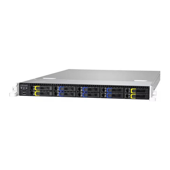
About the Product The following views show you the product. 1.5.1 System Front View http://www.tyan.com... - Page 26 M1706G62-FPB I/O and LED Indication Power/ID LED LAN2 LED LAN1 LED Warning (IPMI) LED HDD LED Power Button ID Button Reset Button USB Ports NOTE: HDD form factor and capacity size support: 2.5” Enterprise 15mm SATA & SAS HDD http://www.tyan.com...
-
Page 27: Led Definitions
Power up and power down the system(Use a pin) Press once the ID (UID) on the Front Panel, the blue ID ID(UID) LED on the rear panel will light up. The Power LED on the front panel will turn blue. Reset Press to reset the system. http://www.tyan.com... -
Page 28: System Rear View
System Rear View B7076G62BV10H Power Supply LAN2 Port (i350) USB3.0 Ports VGA Port Serial Port (COM1) ID LED Button Expansion Slot (support full-height card) Expansion Slot (support half-height card) LAN1 Port (Intel i350, shared with IPMI) ID LED (blue) http://www.tyan.com... - Page 29 B7076G62BV6E4HR & B7076G62BV10HR 1+1 RPSU LAN2 Port (i350) USB3.0 Ports VGA Port Serial Port (COM1) ID LED Button Expansion Slot (support full-height card) Expansion Slot (support half-height card) LAN1 Port (Intel i350, shared with IPMI) ID LED (blue) http://www.tyan.com...
-
Page 30: Motherboard (S7076) Layout
The board you receive may not look exactly like the above diagram. The DIMM slot numbers shown above can be used as a reference when reviewing the DIMM population guidelines shown later in the manual. For the latest board revision, please visit our web site at http://www.tyan.com. http://www.tyan.com... -
Page 31: Jumpers & Connectors
41 ATX 24-pin Main Power Connector 19 Front Panel Header (J50) (PW2) 20 PCH SATA SGPIO Header for BB HD 42 TYAN Module Header (J48) Board (J43) 21 USB3.0 Header (J36) 43 FAN Header for BB FAN Board (J29) 22 7-pin Vertical SATA3.0 Connector... - Page 32 CPU0_DIMM_A0/A1 CPU1_DIMM_G0/G1 CPU1_DIMM_H0/H1 CPU1_DIMM_F0/F1 CPU1_DIMM_E0/E1 Jumper Legend OPEN - Jumper OFF Without jumper cover CLOSED - Jumper ON With jumper cover http://www.tyan.com...
-
Page 33: System Architecture Scheme
1.5.6 System Architecture Scheme http://www.tyan.com... -
Page 34: System Top View
1.5.7 System Top View B7076G62BV10H HDD Trays M1706G62-FPB and Front Panel Tray M1264G62-BP12-10 HDD Backplane Board System Fans Power Supply http://www.tyan.com... - Page 35 B7076G62BV10HR HDD Trays M1706G62-FPB and Front Panel Tray M1264G62-BP12-10 HDD Backplane Board System Fans 1+1 RPSU http://www.tyan.com...
- Page 36 B7076G62BV6E4HR HDD Trays M1706G62-FPB and Front Panel Tray M1274G62-BP12E-10 HDD Backplane Board System Fans 1+1 RPSU http://www.tyan.com...
-
Page 37: Chapter 2: Setting Up
Caution! To avoid damaging the motherboard and associated components, do not use torque force greater than 7kgf/cm (6.09 lb/in) on each mounting screw for motherboard installation. Do not apply power to the board if it has been damaged. http://www.tyan.com... -
Page 38: Precautions
Working on a system that is connected to a power supply can be extremely dangerous. Follow the guidelines below to avoid damage to GT62B-B7076 or injury to yourself. Ground yourself properly before removing the top cover of the system. -
Page 39: Installing Motherboard Components
CPUs, memory modules, HDD and PCI-E cards. 2.1.1 Removing the Chassis Cover Follow these instructions to remove the GT62B-B7076 chassis cover. Loosen the screw on the left side and the thumb screw on the back side. Slide the top cover out. - Page 40 http://www.tyan.com...
-
Page 41: Installing The Cpu And Heatsink
Follow the steps below on installing CPUs and CPU heatsinks. Locate the CPU sockets. Always start with CPU0 first. Pull the levers slightly away from the socket and then push them to a fully open position. Push the CPU socket cover to a fully open position. http://www.tyan.com... - Page 42 Take out the protection cap when installing the CPU. Place the CPU into the socket and make sure that the gold arrow is located in the right direction. Close the CPU socket cover and press the levers down to secure the CPU. http://www.tyan.com...
- Page 43 Position the heatsink on top of the CPU and secure it with 4 screws. http://www.tyan.com...
-
Page 44: Installing The Pci-E Card
2.1.3 Installing the PCI-E Card Follow these instructions to install the PCI-E card. Unscrew to take off the Riser Bracket. Unscrew to take off the PCI-E dummy brackets. http://www.tyan.com... - Page 45 Insert the PCI-E card and screw it to the Riser Bracket. Replace the Riser Bracket. http://www.tyan.com...
-
Page 46: Installing The Memory
Align the memory module with the slot. When inserted properly, the memory slot locking levers lock automatically onto the indentations at the ends of the module. Follow the recommended memory population table to install the other memory modules. http://www.tyan.com... - Page 47 S7076 Recommended Memory Population Table Single CPU Installed (CPU0 only) Quantity of memory installed √ √ √ √ √ √ CPU0_DIMM_A0 √ √ CPU0_DIMM_A1 √ √ √ √ √ CPU0_DIMM_B0 √ √ CPU0_DIMM_B1 √ √ √ CPU0_DIMM_C0 √ CPU0_DIMM_C1 http://www.tyan.com...
- Page 48 √ √ √ √ √ CPU1_DIMM_E0 √ √ √ CPU1_DIMM_E1 √ √ √ √ √ √ CPU1_DIMM_F0 √ CPU1_DIMM_F1 √ √ √ √ √ √ √ √ CPU1_DIMM_G0 √ √ CPU1_DIMM_G1 √ √ √ √ √ CPU1_DIMM_H0 √ CPU1_DIMM_H1 http://www.tyan.com...
-
Page 49: Installing Hard Drives
2.1.5 Installing Hard Drives Follow these instructions to install a hard drive. Pull the locking lever open. Slide the HDD tray out. Unscrew the HDD tray bracket. http://www.tyan.com... - Page 50 Place a hard drive into the drive tray and use 4 screws to secure the HDD. Reinsert the HDD tray into the chassis and push the locking lever back to secure the tray. http://www.tyan.com...
-
Page 51: Rack Mounting
Screws Kit x 1 Mounting Brackets x 4 Installing the Server in a Rack Follow these instructions to mount the TYAN GT62B-B7076 into an industry standard 19" rack. NOTE: Before mounting the TYAN GT62B-B7076 in a rack, ensure that all internal components have been installed and that the unit has been fully tested. -
Page 52: Installing The Inner Rails To The Chassis
2.2.1 Installing the inner Rails to the Chassis Screw the mounting ear to each side of TYAN KGT62A as shown using two screws of #6-32 L5.3(D) from the supplied screws kit. Draw out the inner rails from rail assembly. Install inner rails to left and right sides of chassis using 1 M4-4L(A) screw for each side. -
Page 53: Installing The Outer Rails To The Rack
Rear Bra cket x 2 Front Brack et x2 Secure the front bracket to outer rail with 2 M4-4L(A) screws. Reserve the distance same as in Step 2 on rear bracket. Secure the rear bracket to outer rail with 2 M4-4L(B) screws. http://www.tyan.com... - Page 54 Secure the outer rail to the rack using 2 brackets and 4 M5-20L(C) screws for each side. Secure the mounting brackets from inside, not outside, of the rack. Mounting Bra cket http://www.tyan.com...
-
Page 55: Rack Mounting The Server
Draw out the middle rail to the latch position. Lift the chassis and then insert the inner slide rails into the middle rails. Push the chassis in and press the latch key (A). Then push the whole system into the rack (B). http://www.tyan.com... - Page 56 Secure the mounting ears of chassis to the rack with 2 M5-15L(C) screws. NOTE: To avoid injury, it is strongly recommended that two people lift the TYAN GT62B-B7076 into the place while a third person screws it to the rack. http://www.tyan.com...
- Page 57 NOTE http://www.tyan.com...
-
Page 58: Chapter 3: Replacing Pre-Installed Components
This chapter explains how to replace the pre-installed components, including the S7076 Motherboard, M1706G62-FPB Front Panel Board, M1264G62B-BP12-10 / M1274G62B-BP12E-10 SATA/SAS HDD Backplane Board, PCI-E Card, System Fan and Power Supply Unit etc. 3.0.2 Disassembly Flowchart The following flowchart outlines the disassembly procedures. http://www.tyan.com... -
Page 59: Removing The Cover
Removing the Cover Before replacing any parts you must remove the chassis cover. Follow Section 2.1.1 Removing the Chassis Cover (page 39) to remove the cover of the GT62B-B7076. Removing Motherboard Procedures Follow these instructions to replace the motherboard. 3.2.1... - Page 60 http://www.tyan.com...
- Page 61 http://www.tyan.com...
-
Page 62: Removing The Motherboard
After removing all of the aforementioned cables, follow these instructions to remove the motherboard from the chassis. Remove the heatsinks and processors if installed. Remove the nine screws securing the motherboard to the chassis. Carefully lift the motherboard from the chassis as the image shows. http://www.tyan.com... -
Page 63: Replacing The Front Panel Board
Replacing the Front Panel Board Follow these instructions to replace the M1706G62-FPB Front Panel Board. Release cables from the cable clip. Unscrew the front panel tray. Pull the front panel tray from the chassis. Disconnect cables from the front panel board. http://www.tyan.com... - Page 64 Unscrew the Front Panel Board to replace a new one. Follow the steps described earlier in reverse to reinstall the USB Board. Repeat the procedures described earlier in reverse order to place the front panel tray back into place. http://www.tyan.com...
-
Page 65: Front Panel Board Features
Pin Net Name Function Pin Net Name Function VCC_USB0 Power connect to 5V (for USB) 6 USB_P1_P USB_P1 + VCC_USB1 Power connect to 5V (for USB) 7 Ground USB_P0_N USB_P0 - Ground USB_P1_N USB_P1 - USB_P0_P USB_P0 + 10 NC http://www.tyan.com... -
Page 66: Replacing The System Fans
Replacing the System Fans Follow these instructions to replace the system fans. Disconnect the fan power cords from the HDD backplane board. Take out the failed fan. http://www.tyan.com... - Page 67 Pull the front rubber screws out. Pull the rear rubber screws out. After replacing the new fan, follow the steps described earlier in reverse order to reinstall the fan into the chassis. http://www.tyan.com...
- Page 68 Connect the fan cables to the backplane fan connectors. http://www.tyan.com...
-
Page 69: Replacing The Hdd Backplane Board
1. M1264G62B-BP12-10: B7076G62BV10H and B7076G62BV10HR 2. M1274G62B-BP12E-10: B7076G62BV6E4HR Disconnect all cables attached to the HDD BP Board. Unscrew to lift the HDD Backplane bracket up. Loosen 8 screws to lift up the mylar and replace with a new HDD BP Board. http://www.tyan.com... -
Page 70: Hdd Backplane Board Specifications
(2) 4-in-1 Mini SAS HD connectors to MB (2) Big 4-pin HDD power connector (2) 7-pin SATA HDD connector (10) HDD Access LEDs (Front view, lower) LEDs (10) HDD Failed LEDs (Front view, upper) http://www.tyan.com... - Page 71 (2+1) 4Pin power connector connect to MB (2) 2x5 pin JTAG connector (TBD) (1) 2x5 pin SGPIO connector connect to MB (10) Green LEDS for HDD activity LEDs (10) Red LEDS for HDD fault http://www.tyan.com...
- Page 72 J29: Front Panel Connector Signal Signal TACH1 TACH6 TACH2 TACH7 TACH3 TACH8 TACH4 TACH9 TACH5 TACH10 TACH11 TACH12 FAN1/2/3/4/5/6: 8-pin Fan Header Signal Signal PWM1 VCC1 TACK1 GND1 GND2 TACK2 VCC2 PWM2 http://www.tyan.com...
-
Page 73: Hdd Bp Board Led Definitions
Identify (Locate the HDD) Blinking(1Hz) Don’t care Rebuild Blinking(4Hz) Don’t care NOTE: Some RAID cards have compatibility issue, therefore, when the HDD is under the HDD Fail, Identify or Rebuild state, simply ignore the Activity LED and focus on the Status LED. http://www.tyan.com... -
Page 74: Replacing The Power Distribution Board (Optional)
Replacing the Power Distribution Board (optional) Follow these instructions to replace the power distribution board. This M7016-B7066 section is for B7076G62BV10HR and B7076G62BV6E4HR only. Press the latch to pull the two power supplies out. http://www.tyan.com... - Page 75 Disconnect the cables from the M7016-B7066 power distribution board. Remove six (6) screws that secure the power distribution board to the chassis. After replacing a new power distribution board, follow the procedures in reverse order to reinstall the power distribution board back into the chassis. http://www.tyan.com...
-
Page 76: Power Distribution Board Feature
36.7 x 420.40 x 2mm, 6-layer PCB (1) ATX 24pin Power Connector (2) 2x4pin Power Connector (2) Power input Connector Integrated I/O (2) 1x4pin Power Connector (1) 2x2pin Power Connector (1) PSMI Connector http://www.tyan.com... -
Page 77: Power Distribution Board Pin Definitions
Power Distribution Board Pin Definitions ATX1 Definition Definition +12V2 +12V2 +12V3b +12V3b ATX2 Definition Definition +12V1 +12V1 +12V3a +12V3a PW1: 24-pin Power Connector Definition Definition 3.3V 3.3V Power Good 5VSB +12V +12V 3.3V 3.3V +12V PS_ON Reset PW2/PW3: 4-pin Power Connector Definition +12V http://www.tyan.com... - Page 78 PW4: 4-pin Power Connector Definition Definition +12V +12V J4: PSMI Connector Definition SMBUS_CLK SMBUS_DATA http://www.tyan.com...
-
Page 79: Replacing The Power Supply
Please unplug the power cord before you follow these instructions to replace the power supply units. B7076G62BV10H Disconnect the power cables from and the M1277. Disconnect the power cables from and the Motherboard. Remove seven (7) screws that secure the power supply with bracket to the chassis. http://www.tyan.com... - Page 80 Slide out the power supply unit. Unscrew the power supply bracket. http://www.tyan.com...
- Page 81 After replacing a new power supply unit, follow the procedures in reverse order to reinstall the power supply back into the chassis. http://www.tyan.com...
- Page 82 B7076G62BV6E4HR & B7076G62BV10HR Located the power supply cage. Press the latch to pull the power supply out. http://www.tyan.com...
- Page 83 After replacing a new power supply, press and hold the latch to push the power supply back into the chassis. http://www.tyan.com...
-
Page 84: Appendix I: Cable Connection Tables
→ Fan4 FAN4 → Fan5 FAN5 → Fan6 FAN6 System Fan to M1274 Backplane (BP) Board System Fan Connect to M1274 → Fan1 FAN1 → Fan2 FAN2 → Fan3 FAN3 → Fan4 FAN4 → Fan5 FAN5 → Fan6 FAN6 http://www.tyan.com... - Page 85 SATA CABLE → SGPIO CABLE SGPIO → FAN CABLE M1274 Backplane (BP) Board to S7076 MB M1274 Connect to S7076GM2NRE Mini-SAS HD → NVMe0 CABLE Mini-SAS HD → NVMe1 CABLE Mini-SAS HD → NVMe2 CABLE Mini-SAS HD → NVMe3 CABLE http://www.tyan.com...
- Page 86 PSMI P8 PSU to M1264 Backplane (BP) Board Connect to M1264 → B4P P4 → B4P P5 5. Power Cables (FOR REDUNDANT SKU) M7016-PDB to S7076 MB M7016 Connect to S7076 → PWR1 2x12P CABLE → ATX1 2x4P CABLE http://www.tyan.com...
- Page 87 M7016-PDB to M1264 Backplane (BP) Board M7016 Connect to M1264 → B4P CABLE 1x4P PWR → 1x4P PWR B4P CABLE M7016-PDB to M1274 Backplane (BP) Board M7016 Connect to M1274 → 1x4P PWR B4P CABLE → 1x4P PWR B4P CABLE http://www.tyan.com...
-
Page 88: Appendix Ii: Fan And Temp Sensors
This section aims to help readers identify the locations of some specific FAN and Temp Sensors on the motherboard. A table of BIOS Temp sensor name explanation is also included for readers’ reference. NOTE: The red mark indicates the sensor. http://www.tyan.com... - Page 89 (rpm) Temp Sensor: Temp. Temp sensor detects the system temperature around. NOTE: The system temperature is measured in a scale defined by Intel, not in Fahrenheit or Celsius. BIOS Temp Sensor Name Explanation: http://www.tyan.com...
- Page 90 Interface (PECI) PCH_Area_Temp Temperature of the PCH Area SAS_Area_Temp Temperature of the SAS Area (reserved for TYAN OCP SAS Card) LAN_Area_Temp Temperature of the LAN Area (reserved for TYAN OCP LAN Card) SYS_Inlet_Temp Temperature of the Air Inlet Area (reserved for TYAN FPB)
- Page 91 Temperature of CPU1 DIMM D0 Slot CPU1_DIMM_D1 Temperature of CPU1 DIMM D1 Slot SYS_FAN_1 Fan Speed of SYS_FAN_1 SYS_FAN_2 Fan Speed of SYS_FAN_2 SYS_FAN_3 Fan Speed of SYS_FAN_3 SYS_FAN_4 Fan Speed of SYS_FAN_4 SYS_FAN_5 Fan Speed of SYS_FAN_5 SYS_FAN_6 Fan Speed of SYS_FAN_6 http://www.tyan.com...
-
Page 92: Appendix Iii: Fru Parts Table
Appendix III: FRU Parts Table GT62B-B7076 FRU Parts Item Model Number Part Number Picture Description M2091 411739100498 M2091 PCBA M2091-R 411T50200010 M2091-R MINI-SAS HD CABLE, SHORT MINI-SAS HD TO SHORT MINI-SAS, 450 MM FRU-CS-0190 422T51400001 MINI-SAS HD CABLE, SHORT MINI-SAS... - Page 93 Rack Mounting CRAL-0034 452T15200001 Slide Rail Kit 1U-PASSIVE HEATSINK, Heatsink FRU-TH-0130 343T51400003 105.5X80X25.5MM,SCREW http://www.tyan.com...
-
Page 94: Appendix Iv: Technical Support
By offering plenty of options for users, MiTAC serves multiple market segments with the industry’s most competitive services to support them. Please feel free to contact us directly for this service at tech-support@tyan.com Help Resources: 1. See the beep codes section of this manual. - Page 95 (RMA) number. The RMA number should be prominently displayed on the outside of the shipping carton and the package should be mailed prepaid. TYAN will pay to have the board shipped back to you. TYAN® GT62B-B7076 Service Engineer’s Manual V1.1a Document No.: D2282-110 http://www.tyan.com...
Need help?
Do you have a question about the GT62B-B7076 and is the answer not in the manual?
Questions and answers