Table of Contents
Advertisement
Quick Links
Advertisement
Table of Contents

Related Manuals for TYAN GT20 B7002


Summary of Contents for TYAN GT20 B7002
- Page 1 ® TYAN GT20 B7002 Service Engineer’s Manual...
- Page 2 http://www.tyan.com...
- Page 3 Corporation and has been reviewed for accuracy and reliability prior to ® printing. TYAN assumes no liability whatsoever, and disclaims any ® express or implied warranty, relating to sale and/or use of TYAN products including liability or warranties relating to fitness for a particular purpose or ® merchantability. TYAN retains the right to make changes to produce descriptions and/or specifications at any time, without notice.
- Page 4 There will be danger of explosion if battery is incorrectly replaced. Replace only with the same or equivalent type recommended by manufacturer. Dispose of used battery according to manufacturer instructions and in accordance with your local regulatio- -ns. http://www.tyan.com...
- Page 5 About this Manual This manual provides you with instructions on installing your ® TYAN GT20. This Manual is intended for experienced users and integrators with hardware knowledge of personal computers. This manual consists of the following parts: Chapter1: Provides an introduction to the GT20-B7002 bare-...
- Page 6 ·When service or repairs have been done, perform routine safety checks to verify that the system is operating correctly. ·Avoid using the system near water, in direct sunlight, or near a heating device. ·Cover the unit when not in use. http://www.tyan.com...
-
Page 7: Table Of Contents
Table of Contents Chapter 1: Overview ................. 9 1.1 About the TYAN GT20-B7002............ 9 1.2 Product Models................. 10 1.3 Features ................... 11 1.4 Standard Parts List ..............15 1.4.1 Box Contents ..............15 1.4.2 Accessories ............... 16 1.5 Optional Parts................17 1.6 About the Product.............. - Page 8 3.7.2 M1232 HDD/FAN Board Connector Pin Definitions ..61 Appendix I: BIOS Differences............65 Appendix II: Replacing Slim DVD-ROM (Optional) ...... 67 Appendix III: Cable Connection Tables ........69 Appendix IV: FRU Parts Table ............71 Appendix V: Technical Support ............ 73 http://www.tyan.com...
-
Page 9: Chapter 1: Overview
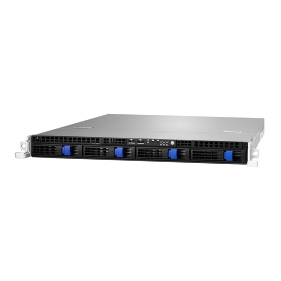
Chapter 1: Overview About the TYAN GT20-B7002 ® Congratulations on your purchase of the TYAN GT20-B7002, a highly- -optimized rack-mountable barebone system. GT20-B7002 is designed to ® support up to two Intel “Nehalem-EP 2S” processors and up to 64GB DDR3-800/1066/1333 memory, providing a rich feature set and incredible ®... -
Page 10: Product Models
Product Models Model HDD Bays Power supply Removable, B7002G20V4H 400W single 4HDDs http://www.tyan.com... -
Page 11: Features
Features TYAN GT20-B7002 (B7002G20V4H) 1U Rackmount Form Factor Chassis Name GT20 System Dimension (D x W x H) 22.4" x 17.2" x 1.72" (568 x 436 x 43.6mm) S7002GM2NR-LE Motherboard Gross Weight 17.7kg Buttons (1) PWR / (1) RST / (1) NMI / (1) ID... - Page 12 Memory Capacity Up to 64GB Memory channel 3-Channel 1.5V Memory voltage PCI-E (1) PCI-E x16 slot Expansion Pre-install TYAN Riser Slots M2083-RS, PCI-E x16 1U riser card (left) Card Port QTY Controller Intel 82574 D-Sub 15pin Connector type Graphic Resolution...
- Page 13 Humidity RoHS RoHS 6/6 Complaint Motherboard (1) S7002GM2NR-LE Manual (1) User's manual / (1) Quick Ref. Guide Package (1) TYAN installation CD Installation CD Contains I/O Shield (1) I/O Shield (1) CCHA-0350, GT20 1U chassis unit (for Chassis Unit B7002)
- Page 14 (1) CFBZ-0070, Front bezel for GT series 1U Front Bezel chassis Optional CRAL-0032, Rail kit / (1) CEAR-0050, Rack Mounting Part accessories for mounting ear kit future upgrade (1) CDVD-0060, slim type DVD-ROM / (1) Peripheral CCBL-0422, slim ODD SATA cable(1) CCBL-0326,SATA cable http://www.tyan.com...
-
Page 15: Standard Parts List
The product should arrive packaged as illustrated below. 1.4.1 Box Contents Component Description 1U chassis,(4) hot swap HDDbays ® TYAN S7002 system board (pre-installed) 400W single Power Supply (5) System FAN M1008: LED control board (pre-installed) M1232 HDD/Fan Board M2083-RS PCI-E riser card http://www.tyan.com... -
Page 16: Accessories
If any items are missing or appear damaged, contact your retailer or ® browse to TYAN ’s website for service: http://www.tyan.com ® The web site also provides information of other TYAN products, as well as FAQs, compatibility lists, BIOS settings, etc. ® 1 x TYAN 1 x Heatsink... -
Page 17: Optional Parts
Rail Kit Rail with Bracket x 2 Screw Sack Optional Parts Model Item Picture Quantity Description Number DVD-ROM CDVD-0060 Slim DVD drive, SATA Chassis Front Bezel for GT series 1U CFBZ-0070 Front-Bezel chassis http://www.tyan.com... -
Page 18: About The Product
ID LED Warning LED Power Status LED(PSMI) USB ports ID button Reset button Power button(with LED) HDD LED(NIC3) NIC2 NMI button NIC1 1.6.2 System Rear View Power supply USB ports LAN1 USB ports LAN2 Serial port & VGA port http://www.tyan.com... -
Page 19: Led Definitions
Description Green 10Mb/100Mb/1000Mb linked RJ-45 Linkage/ Blinking Green 10Mb/100Mb/1000Mb activity Activity(left) No LAN linked Amber 1000Mb linked/activity RJ-45 Linkage/ Green 100Mb linked/activity Activity(Right) 10Mb mode or No LAN linked NOTE: “Left” and “Right” are viewed from the rear panel. http://www.tyan.com... - Page 20 Note: Press ID button when the system is AC (Alternating Current) on, then ID LED will show the system is identified with emitting blue light. Users from remote site could also activate ID LED by input a few commands in IPMI, detailed software support please visit http://www.tyan.com for lastest AST2050 user guide. http://www.tyan.com...
-
Page 21: Motherboard (S7002) Layout
1.6.4 Motherboard (S7002) Layout The diagram is representative of the latest board revision available at the time of publishing. The board you receive may not look exactly like the above diagram. http://www.tyan.com... -
Page 22: Jumpers & Connectors
Front Panel Header Clear CMOS PSMI Connector IPMB Pin Header SGPIO Header BMC RST Button Clear CMOS On Board SAS LSI1068E EN/DIS JP8/JP9 COM2 Select Jumper Legend OPEN - Jumper OFF Without jumper cover CLOSED - Jumper ON With jumper cover http://www.tyan.com... -
Page 23: System Block Diagram
1.6.6 System Block Diagram http://www.tyan.com... -
Page 24: Internal View
1.6.7 Internal View ⑤ ④ ③ ② ① HDD Cage ① M1232 HDD/FAN Board ② System Fan Unit ③ Power Supply ④ M2083 - RS PCI-E Riser Card ⑤ http://www.tyan.com... -
Page 25: Chapter 2: Setting Up
Most of the electrical and mechanical connections can be disconne- -cted with your hands. It is recommended that you do not use pliers to remove connectors as it may damage the soft metal or plastic parts of the connectors. http://www.tyan.com... -
Page 26: Precautions
Metallic parts or metal flakes can cause electrical shorts. Note: All connectors are keyed to only attach one way. All use the correct screw size as indicated in the procedures. http://www.tyan.com... -
Page 27: Installing Motherboard Components
-rd, including CPUs, memory modules and add on cards. 2.1.1 Removing the Chassis Cover Follow these instructions to remove GT20-B7002 chassis cover. Unscrew the rear top cover on the back side as shown in the small diagram. Slide the rear top cover out. http://www.tyan.com... -
Page 28: Installing The Cpu And Heatsink
2.1.2 Installing the CPU and Heatsink Follow the steps below on installing CPUs and CPU heatsinks. 1. Locate the CPU socket. 2. Press the lever and unlock the CPU socket. http://www.tyan.com... - Page 29 3. Lift the CPU protection cap up and lay the CPU into the socket(A), ensuring pin1 is correctly located(B); 4. Close the socket cover and press the CPU lever down to secure the CPU; http://www.tyan.com...
- Page 30 5. Place the heatsink on top of the CPU and secure it with 8 screws. Note: The system supports two CPUs. For CPU sequence please refer to Chapter 1.6.4. http://www.tyan.com...
-
Page 31: Installing The Memory
Press the memory slot locking levers in the direction of the arrows as shown in the following illustration. Align the memory module with the slot. When inserted properly, the memory slot locking levers lock automatically onto the indentations at the ends of the module. http://www.tyan.com... - Page 32 2). Refer to the memory population option table for recommended memory installation instruction. Memory Population Option Table ® To achieve the best performance, TYAN strongly recommended memory installation configuration as listed below: 1. Single CPU installed (CPU0 Only) Quantity of memory...
- Page 33 √ √ √ √ CPU0 DIMM CHC0 √ √ √ √ CPU1 DIMM CHD1 √ CPU1 DIMM CHD0 √ √ √ √ √ √ √ CPU1 DIMM CHE0 √ √ √ √ √ CPU1 DIMM CHF0 √ √ √ http://www.tyan.com...
- Page 34 1). “√”indicates a populated DIMM slot. 2). If installing only one processor, you can choose either CPU0 or CPU1. 3). For two slots per channel configuration, it requires populat- -ion to start with the DIMM slots furthest away from the processor. http://www.tyan.com...
-
Page 35: Installing Hard Drives
The GT20-B7002 supports four 3.5” hard drives. Follow these instructions to install a hard drive. Press the locking lever latch and pull the locking lever open. Slide the HDD tray out. Remove the 6 screws and slide the dummy tray out. http://www.tyan.com... - Page 36 Place a hard drive into the drive tray. Use 6 HDD screws to secure the HDD. http://www.tyan.com...
- Page 37 6. Reinsert the HDD tray into the chassis and press the locking lever to secure the tray. http://www.tyan.com...
-
Page 38: Rack Mounting
Screw Sack Including A: M 5 x 15---------- 4 pcs B: M 5 x 8 -----------10 pcs C: M 4 x 4 -----------18 pcs http://www.tyan.com... -
Page 39: Installing The Inner Rails To The Chassis
Screw the mounting ear to each side of GT20-B7002 as shown using 2 screws from the supplied screws kit. Draw out the inner rails from sliding rails and Install inner rails to left and right sides of chassis using 2 M 4x4 screw for each side. http://www.tyan.com... -
Page 40: Installing The Outer Rails To The Rack
Measure the distance between inner side of the front and rear mounting brackets in the rack. Locate the front and rear brackets. Reserve 4cm on the front bracket. Secure the front bracket to outer rail with 2 M4 x 4 screws. http://www.tyan.com... - Page 41 2 M 4 x 4 screws for each side. Secure the outer rail to the rack using 2 brackets and 4 M 5 x 8 screws for each side (A). Secure the mounting brackets from inside, not outside, of the rack (B). Mounting Bracket http://www.tyan.com...
-
Page 42: Rack Mounting The Server
1. Draw out the middle rail to the latch position. 2. Lift the chassis and then insert the inner slide rails into the middle rails. 3. Press the latch key (A) then push the whole chassis into the sever rack (B). http://www.tyan.com... - Page 43 1 M 5 x 15 screw on each side. Note: To avoid injury, it is strongly recommended that two people lift GT20-B7002 into the place while a third person screws it to the rack. http://www.tyan.com...
- Page 44 http://www.tyan.com...
-
Page 45: Chapter 3: Replacing Pre-Installed Components
HDD/Fan board, M2083-RS PCI-E Riser card, System fan, ODD drive, Power supply unit etc. Disassembly Flowchart The following flowchart outlines the disassembly procedure. Rear Components Chassis rear cover DIMMs Power CPU/Heatsink Assembly PCI Card M2083-RS PCI-E Riser card Mainboard Mainboard http://www.tyan.com... - Page 46 Front Components Chassis rear cover DVD ROM (Optional) PCBs M1008 M1232 HDD/Fan Control Board Board http://www.tyan.com...
-
Page 47: Removing The Cover
Follow the instructions below to disassemble the M2083-RS PCI-E riser card. 1. Locate the riser card on the motherboard, unscrew the bracket from the slot. 2. Unscrew the bracket and pull it up from the slot in the direction as the arrow shows. http://www.tyan.com... - Page 48 3. Unscrew the card from the bracket. 4. Install a new riser card onto the bracket following the above procedures in reverse. http://www.tyan.com...
-
Page 49: Disconnecting All Motherboard Cables
Disconnecting All Motherboard Cables Before replacing the motherboard or certain components, remove cables connected to the motherboard. Follow these instructions to remove all motherboard cables. Disconnect all the power cable. 2. Disconnect SATA cable, Fan cable, USB cable and front panel cable. http://www.tyan.com... -
Page 50: Removing The Motherboard
Remove the nine screws securing the motherboard to the chassis. Carefully lift the motherboard from the chassis as the image shows you. Note: Lift the front edge of the board to an angle of about 45 then slides the whole board out. http://www.tyan.com... -
Page 51: Replacing The Led Control Board
Remove the two screws securing the LED control board unit to the chassis. Push the LED control board unit out and unplug the cables from the connectors at the back of the unit. Remove three screws securing the LED control board to the bracket. http://www.tyan.com... - Page 52 4. Lift the LED control board free from the chassis. After replacem- -ent, insert the unit into the chassis following the above proced- -ures in reverse. http://www.tyan.com...
-
Page 53: M1008 Led Control Board Features
M1008 LED Control Board Connector Pin Definition J1: USB Header Definition Definition USB1- USB2- USB1+ USB2+ J3: SSI Definition Definition PW_LED+ ID_LED+ PW_LED- ID_LED- HD/LAN3 LED+ SYS_FAULT1- HD/LAN3 LED- SYS_FAULT2- PWR_SW+ LAN1_LED+ PWR_SW- LAN1_LED- RESET+ ICH_SMBDAT RESET- ICH_SMBCLK ID_SW+ INTRU# TEMP_SENSER LAN2_LED+ EXT_INT LAN2_LED- http://www.tyan.com... -
Page 54: Replacing The System Fan
Locate the cooling fans in your system. Unplug the cables connected to the HDD/FAN board and lift the fan unit up from the chassis. Install the new fan unit into the chassis after replace the broken single fan following the steps below. http://www.tyan.com... - Page 55 http://www.tyan.com...
- Page 56 http://www.tyan.com...
-
Page 57: Replacing The M1232 Hdd/Fan Board
Replacing the M1232 HDD/FAN Board Step 1: Disconnect all cables connected to M1232 HDD/FAN Board PW cable: FAN cable: SATA cable and fan control cable: http://www.tyan.com... - Page 58 Step 3: Lift the bracket up from the chassis. Step 4: Unscrew M1232 board from the bracket. Step 5: Replace a new M1232 HDD/FAN Board and reinstall it into the chassis following the above steps in reverse. http://www.tyan.com...
-
Page 59: M1232 Hdd/Fan Board Features
3.7.1 M1232 HDD/FAN Board Features Front View J17: SATA Connector FAN7 FAN1 FAN2 FAN3 FAN4 FAN5 J16: SATA Connector FAN6 J39: Mini SAS Connector http://www.tyan.com... - Page 60 Rear View: LED1 LED2 LED4 LED3 LED6 LED5 LED7 LED8 http://www.tyan.com...
-
Page 61: M1232 Hdd/Fan Board Connector Pin Definitions
M1232 HDD/FAN Board Connector Pin Definitions Definition +12V Definition Definition +12V +12V J15 SGPIO JTAG Definition Definition 3.3V J41 SGPIO for IOH Definition Definition SM_CLK SGPIO_0 SM_DATA SGPIO_1 SGPIO_2 SGPIO_3 HD_ERR_LED J5 Slim Hard Disk power Definition +12V J18 Slim CDROM power Definition +12V http://www.tyan.com... - Page 62 Pin 1-2 chose by CPU_PWM (Default) Pin 2-3 chose by CPU_PWM2 LED Definition: Color State Description HDD fail LED Amber SATA/SAS HDD fail (LED 2/4/6/8) No failure found SATA/SAS HDD ready Green Power/Access SATA/SAS HDD Blinking access activity (LED 1/3/5/7) Power disconnected http://www.tyan.com...
-
Page 63: Replacing The Power Supply
Replacing the Power Supply 1. Disconnect the power cables from the motherboard and the HDD/FAN board. 2. Remove the screws that secure the power supply to the chassis. http://www.tyan.com... - Page 64 3. Take out the power unit and install a new one follow the above steps in reverse. http://www.tyan.com...
-
Page 65: Appendix I: Bios Differences
Options each sensor event. Manual Sensor Data Register Monitoring 1x4 FAN ← → Select Screen 1X8 FAN Chassis Sensor Configuration Select Item ↑↓ GT20 Change Option Chassis Select [Auto] GT57 Select Field AUTO General Help Save and Exit Exit http://www.tyan.com... - Page 66 Please be noticed that the BIOS menu are continually changing due to BIOS updating. The BIOS menu provided are the most updated when this manual is written. Please ® visit TYAN ’s website at http://www.TYAN.com for the information of the latest BIOS edition.
-
Page 67: Appendix Ii: Replacing Slim Dvd-Rom (Optional)
GT20-B7002 provides you with an optional slim DVD ROM. Follow these instructions to install the DVD-ROM. Remove the DVD cover from the chassis front panel. Connect the power and SATA cable of the DVD ROM. Push the DVD through the front of the GT20-B7002. http://www.tyan.com... - Page 68 Connect the power cable and DVD SATA cable to the HDD board and mother board. http://www.tyan.com...
-
Page 69: Appendix Iii: Cable Connection Tables
Mini-SAS Cable SATA0~3 → Fan Control Cable M1008 LED Control Board to S7002 Motherboard M1008 Connect to S7002 Motherboard → Control Cable → USB Cable Power Supply Cables PSU to S7002 Connect to S7002 Motherboard → 2X12 PWR → → http://www.tyan.com... - Page 70 PSU to M1232 Connect to M1232 → → http://www.tyan.com...
-
Page 71: Appendix Iv: Fru Parts Table
Chassis Front Bezel CFBZ-0070 541273910008 Chassis HDD Tray CHDT-0051 340746300001 3.5" HDD Tray Power Supply CPSU-0281 471015200218 400W single Power Supply CFAN-0241 336252012294 14700RPM,40*40*28MM,4PIN Heatsink & Cooler CHSK-0370 343782700001 Passive Heatsink Peripheral Drives & CDVD-0060 523410299033 Slim DVD Driver, SATA Parts http://www.tyan.com... - Page 72 CCBL-0422 422772300003 Slim ODD SATA Cable,110mm A/C Power Cord, L=1830mm,US CCBL-0310 332810000280 type A/C Power Cord, L=1830mm,EU CCBL-0300 332810000281 type Note: The table is subject to change without notice. Please visit our Web site at http://www.tyan.com for latest update. http://www.tyan.com...
-
Page 73: Appendix V: Technical Support
's tech support is some of the most impressive we've seen, with great response time and exceptional organization in general.” — Anandtech.com Please feel free to contact us directly for this service at tech-support@tyan.com Help Resources: 1. See the beep codes section of this manual. - Page 74 -mber. The RMA number should be prominently displayed on the outside of the shipping carton and the package should be mailed prepaid. ® TYAN will pay to have the board shipped back to you. ® TYAN GT20-B7002 User’s Manual V1.10 Document No.:...
Need help?
Do you have a question about the GT20 B7002 and is the answer not in the manual?
Questions and answers