Table of Contents
Advertisement
Quick Links
Advertisement
Table of Contents

Related Manuals for TYAN GT24B-B7076


Summary of Contents for TYAN GT24B-B7076
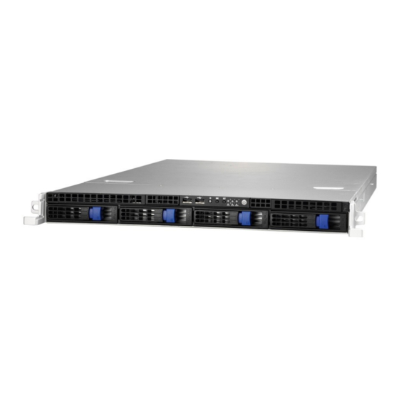
- Page 1 GT24B-B7076 Service Engineer’s Manual...
- Page 2 Neither this manual, nor any material contained herein, may be reproduced without written consent of manufacturer. ® Copyright 2015 MiTAC International Corporation. All rights reserved. TYAN a registered trademark of MiTAC International Corporation. Version 1.0 Disclaimer Information contained in this document is furnished by MiTAC International Corporation and has been reviewed for accuracy and reliability prior to printing.
- Page 3 There will be danger of explosion if battery is incorrectly replaced. Replace only with the same or equivalent type recommended by manufacturer. Dispose of used battery according to manufacturer instructions and in accordance with your local regulations. http://www.tyan.com...
-
Page 4: About This Manual
About this Manual This manual provides you with instructions on installing your TYAN GT24B-B7076.This manual is intended for trained service technician/ personnel with hardware knowledge of computers.. This manual consists of the following parts: Chapter1: Product Introduction Provides an introduction to the TYAN GT24B-B7076 barebones, standard parts list, describes the external components, gives a table of key components, and provides block diagram of the system. -
Page 5: Safety And Compliance Information
Safety and Compliance Information Before installing and using TYAN GT24B-B7076, take note of the following precautions: ·Read all instructions carefully. ·Do not place the unit on an unstable surface, cart, or stand. ·Do not block the slots and opening on the unit, which are provided for ventilation. -
Page 6: Safety Information
You must become familiar with the safety information in this guide before you install, operate, or service TYAN products. Symbols on Equipment Caution. This symbol indicates a potential hazard. -
Page 7: General Precautions
· Do not attempt to move a fully loaded rack. Remove equipment from the rack before moving it. · Do not attempt to move a rack on an incline that is greater than 10 degrees from the horizontal. http://www.tyan.com... - Page 8 This will reduce the risk of personal injury, fire, or damage to the equipment. The total rack load should not exceed 80 percent of the branch circuit rating. Consult the electrical authority having jurisdiction over your facility wiring and installation requirements. http://www.tyan.com...
- Page 9 TYAN, your authorized TYAN partner, or their agents. Equipment Modifications · Do not make mechanical modifications to the system. TYAN is not responsible for the regulatory compliance of TYAN equipment that has been modified.
- Page 10 – Liquid has been spilled on the product or an object has fallen into the product. – The product has been exposed to rain or water. – The product has been dropped or damaged. – The product does not operate normally when you follow the operating instructions. http://www.tyan.com...
-
Page 11: Table Of Contents
Table of Contents Chapter 1: Overview ................ 13 About the TYAN GT24B-B7076 ..........13 Product Model ................ 13 Features ................. 14 Standard Parts List ..............19 1.4.1 Box Contents ..............19 About the Product ..............20 1.6.1 System Front View ............20 1.6.2... - Page 12 M7016-B7066 Power Distribution Board Pin Definitions 75 3.11 Replacing the Redundant Power Supply ......77 Appendix I: Fan and Temp Sensors ..........79 Appendix II: Cable Connection Tables .......... 83 Appendix III: FRU Parts Table ............85 Appendix IV: Technical Support ............. 86 http://www.tyan.com...
-
Page 13: Chapter 1: Overview
IT demand but also offers a smooth path for future application usage. ® TYAN also offers the GT24B-B7076 in a version that can support up to to four ® hot-swap hard drives. The GT24B-B7076 uses TYAN ’s latest chassis, featuring a... -
Page 14: Features
Features TYAN GT24B7076 (B7076G24BV4HR) Form Factor 1U Rackmount Gross Weight 16 kg Chassis Model GT24B System Dimension (D x W x 25.4" x 17.2" x 1.72" (645 x 436 x 43.6mm) Motherboard S7076GM2NR Board Dimension EATX, 12"x13" (305x330mm) Buttons (1) PWR / (1) RST / (1) NMI / (1) ID... - Page 15 Broadcom 10GbE Mezz Card M7076-X540-2T, PCI-E Recommended Gen3 x8, Intel 10GbE Mezz Card M7076-I350, PCI-E TYAN OCP Card Gen3 x8, Intel (2)GbE Mezz Card M7062-I599-1T, PCI-E Gen3 x8, Intel 10GbE Mezz Card M7062-I599-2T, PCI-E Gen3 x8, Intel 10GbE Mezz Card...
- Page 16 RoHS RoHS 6/6 Compliant Yes Barebone (1) GT24B-B7076 Package Manual (1) Quick Installation Guide Contains Installation CD (1) TYAN installation CD TYAN GT24B7076 (B7076G24BV4H) Form Factor 1U Rackmount Gross Weight 16 kg Chassis Model GT24B System Dimension (D x W x 25.4"...
- Page 17 Expansion PCI-E Gen3 x8, LSI SAS 12G Mezz Card Recommended Slots M7094-2308G-8I, PCI-E Gen3 x8, LSI SAS 6G Mezz TYAN OCP Card Card M7076-3008-8I, PCI-E Gen3 x8, LSI SAS 12G Mezz Card M7076-I350, PCI-E Gen3 x8, Intel (2)GbE Mezz Card...
- Page 18 - 40° C ~ 70° C (-40° F ~ 158° F) Temp. Environment In/Non-operating 90%, non-condensing at 35° C Humidity RoHS 6/6 RoHS Compliant Barebone (1) GT24B-B7076 Package Manual (1) Quick Installation Guide Contains Installation CD (1) TYAN installation CD http://www.tyan.com...
-
Page 19: Standard Parts List
Standard Parts List This section describes GT24B-B7076 package contents and accessories. Open the box carefully and ensure that all components are present and undamaged. The product should arrive packaged as illustrated below. 1.4.1 Box Contents GT24B-B7076 Box Content (1) 1U chassis ... -
Page 20: About The Product
About the Product The following views show you the product. 1.6.1 System Front View M1008-G2024 FPB http://www.tyan.com... -
Page 21: System Rear View
1.6.2 System Rear View B7076G24BV4H B7076G24BV4HR http://www.tyan.com... -
Page 22: Led Definitions
10 Mbps Active Blinking Green Solid Green Link Green 100 Mbps Solid Green Active Blinking Green Solid Yellow Link Green 1000 Mbps Solid Yellow Active Blinking Green No Link NOTE: “Left” and “Right” are viewed from the rear panel. http://www.tyan.com... - Page 23 Status LED Activity LED Color: Orange Color: Green No Driver Present or power disconnected Driver Present No Activity On Solid Access Activity Blinking HDD Fail On Solid Don’t care Identify (Locate the HDD) Blinking(1Hz) Don’t care Rebuild Blinking(4Hz) Don’t care http://www.tyan.com...
-
Page 24: Motherboard (S7076) Layout
1.6.4 Motherboard (S7076) Layout The diagram is representative of the latest board revision available at the time of publishing. The board you receive may not look exactly like the above diagram. http://www.tyan.com... -
Page 25: Jumpers & Connectors
19 PCH SATA SGPIO Header for BB HD 40 ATX 24-pin Main Power Connector Board (J43) (PW2) 20 USB3.0 Header (J36) 41 TYAN Module Header (J48) 21 7-pin Vertical SATA3.0 Connector 42 FAN Header for BB FAN Board (J29) (SATA4, J45) 43 PSMI Pin Header (J49) - Page 26 CPU0_DIMM_B0/B1 CPU0_DIMM_A0/A1 CPU1_DIMM_G0/G1 CPU1_DIMM_H0/H1 CPU1_DIMM_F0/F1 CPU1_DIMM_E0/E1 Jumper Legend OPEN - Jumper OFF Without jumper cover CLOSED - Jumper ON With jumper cover http://www.tyan.com...
-
Page 27: System Block Diagram
1.6.6 System Block Diagram http://www.tyan.com... -
Page 28: Internal View
1.6.7 Internal View B7076G24BV4H HDD Cage M1277 HDD Backplane System Fans PCI-E Riser Card Assembly 500W Power Supply http://www.tyan.com... - Page 29 B7076G24BV4HR HDD Cage M1277 HDD Backplane System Fans M7016 Power Distribution Board 450W Power Supply x2 PCI-E Riser Card Assembly http://www.tyan.com...
-
Page 30: Chapter 2: Setting Up
A grounding strap or an anti-static pad Most of the electrical and mechanical connections can be disconnected with your hands. It is recommended that you do not use pliers to remove connectors as it may damage the soft metal or plastic parts of the connectors. http://www.tyan.com... -
Page 31: Precautions
Working on a system that is connected to a power supply can be extremely dangerous. Follow the guidelines below to avoid damage to GT24B-B7076 or injury to yourself. Ground yourself properly before removing the top cover of the system. -
Page 32: Installing Motherboard Components
2.1.1 Removing the Chassis Cover Follow these instructions to remove GT24B-B7076 chassis cover. 1. Remove the screw on the right side, and unscrew the rear top cover on the back side, then push latches on the top cover as the arrow show until the cover is released 2. -
Page 33: Installing The Cpu And Heatsink
Follow the steps below on installing CPUs and CPU heatsinks. Locate the CPU socket, always starts with CPU0. Pull the lever slightly away from the socket and then push it to a fully open position. Push the CPU socket cover to a fully open position. http://www.tyan.com... - Page 34 Take out the protection cap. Place the CPU into the socket and make sure that the gold arrow is located in the right direction. Close the CPU socket cover and press the lever down to secure the CPU. http://www.tyan.com...
- Page 35 Position the heatsink on top of the CPU and secure it with 2 screws. Repeat the procedures mentioned earlier to install the second CPU and heatsink. http://www.tyan.com...
-
Page 36: Installing The Pci-E Cards
2.1.3 Installing the PCI-E Cards The GT24B-B7076 supports one PCI-E expansion slot. Follow these instructions to install the PCI-E card. 1. Unscrew the riser card bracket from the chassis. http://www.tyan.com... - Page 37 2. Release the screws on both sides of the PCIE dummy bracket as shown. 3. Remove the PCI-E cover shields from the chassis. 4. Insert the PCI-E card in the direction of arrows as shown. http://www.tyan.com...
- Page 38 5. Screw the PCI-E cards firmly to the riser card bracket. 6. Secure the riser card bracket to the chassis with two screws. http://www.tyan.com...
- Page 39 7. The installation of PCI-E expansion card is now complete. http://www.tyan.com...
-
Page 40: Installing The Memory
3. Align the memory module with the slot. When inserted properly, the memory slot locking levers lock automatically onto the indentations at the ends of the module. Follow the recommended memory population table to install the other memory modules. http://www.tyan.com... - Page 41 http://www.tyan.com...
- Page 42 √ √ √ √ CPU0_DIMM_C0 CPU0_DIMM_C1 √ CPU0_DIMM_D0 √ √ √ √ √ √ √ CPU0_DIMM_D1 √ CPU1_DIMM_E0 √ √ √ √ √ √ √ √ √ √ √ √ √ CPU1_DIMM_E1 CPU1_DIMM_F0 √ √ √ √ √ √ http://www.tyan.com...
- Page 43 CPU1_DIMM_F1 √ CPU1_DIMM_G0 √ √ √ √ √ √ √ √ CPU1_DIMM_G1 √ √ √ √ √ √ √ CPU1_DIMM_H0 CPU1_DIMM_H1 √ http://www.tyan.com...
-
Page 44: Installing Hard Drives
2.1.5 Installing Hard Drives The GT24B-B7076 supports four 3.5” hard drives. Follow these instructions to install a hard drive. Warning!!! Always install the hard disk drive to the chassis after the chassis has been secured on the rack. Installing 3.5“HDDs 1. - Page 45 Remove the 6 screws. Place a hard drive into the drive tray. Use 6 HDD screws to secure the HDD. http://www.tyan.com...
- Page 46 Reinsert the HDD tray into the chassis. Push to secure the locking lever until it clicks into place. http://www.tyan.com...
- Page 47 1. Press the locking lever latch and pull the locking lever open. 2. Slide the HDD tray out. 3. Turn the HDD tray over and place the 2.5” HDD on its bay. Secure the HDD to the tray using 4 screws. http://www.tyan.com...
- Page 48 Reinsert the HDD tray into the chassis. Push to secure the locking lever until it clicks into place. http://www.tyan.com...
-
Page 49: Rack Mounting
19" rack. NOTE: Before mounting the TYAN GT24B-B7076 in a rack, ensure that all internal components have been installed and that the unit has been fully tested. However, to make the installation easier, we suggest that you remove all HDD trays before you insert the chassis into the rack. - Page 50 Installing the Inner Rails to the Chassis 1. Screw the mounting ears to each side of the GT24B-B7076 as shown using four screws from the supplied mounting ears screw pack. 2. Draw out the inner rail from the rail assembly. When the rail comes to a stop, pull the tab to release the latch and completely draw the inner rail out.
- Page 51 (2) to secure the three hooks Secure the inner sliding rail to the server using one M4 x 4L screw (B). 5. Repeat steps 2 to 4 to secure the sliding rail to the other side of the server. http://www.tyan.com...
- Page 52 Secure the outer rails to the rack using four M5 screws and four washers (A) on each side. Rack Mounting the Server Draw out the middle rail to the latch position. Lift the unit and then insert the inner slide rails into the middle rails. http://www.tyan.com...
- Page 53 When the inner rails come to a stop, pull the tab to release the latch and push the whole system in. Secure the mounting ears of the unit to the rack using two M5 x 20L screws (C). http://www.tyan.com...
- Page 54 NOTE http://www.tyan.com...
-
Page 55: Chapter 3: Replacing Pre-Installed Components
This chapter explains how to replace the pre-installed components, including the Motherboard, M1008-G2024-FPB LED control board, M1277 G24-BP12-4 Backplane, M7016-B7066 Power Distribution board, M2091/M2091-R PCI-E Riser card, System fan, ODD drive, Power supply unit etc. Disassembly Flowchart The following flowchart outlines the disassembly procedure. http://www.tyan.com... -
Page 56: Removing The Cover
Removing the Cover Before replacing any parts you must remove the chassis cover first. Follow Chapter 2.1.1 to remove the cover of the GT24B-B7076. Replacing Motherboard Components Follow these instructions to replace motherboard components, including the motherboard. 3.4.1 Replacing Expansion Card The GT24B-B7076 has preinstalled PCI-E ×16 riser cards,... -
Page 57: Pci-E Riser Cards Specification
3.4.2 PCI-E Riser Cards Specification M2091 riser card M2091-R riser card http://www.tyan.com... -
Page 58: Disconnecting All Motherboard Cables
3.4.3 Disconnecting All Motherboard Cables Before replacing the motherboard or certain components, remove cables connected to the motherboard. Follow these instructions to remove all motherboard cables. Disconnect all power cables and PSMI,SGPIO cable. Disconnect all other cables. http://www.tyan.com... -
Page 59: Removing The Motherboard
After removing all of the aforementioned cables, follow the instructions below to remove the motherboard from the chassis. Remove the heatsinks and processors if installed. Remove the nine screws securing the motherboard to the chassis. Carefully lift the motherboard from the chassis. http://www.tyan.com... -
Page 60: Replacing The Led Control Board
Follow these instructions to replace the M1008 LED control board. Remove the two screws securing the LED control board unit to the chassis. Push the LED control board unit out and unplug the cables from the connectors at the back of the unit. http://www.tyan.com... - Page 61 Remove three screws securing the LED control board to the bracket. Lift the LED control board free from the chassis. After replacing the LED control board, insert the unit into the chassis following the above procedures in reverse http://www.tyan.com...
-
Page 62: M1008-G2024 Led Control Board Features
3.6.1 M1008-G2024 LED Control Board Features 3.6.2 M1008-G2024 LCB Connector Pin Definition http://www.tyan.com... - Page 63 Definition Definition USB1- USB2- USB1+ USB2+ J3:2x15-pin SSI Front Panel Header Definition Definition PW_LED+ ID_LED+ PW_LED- ID_LED- HDD LED+ SYS_FAULT1- HDD LED- SYS_FAULT2- PWR_SW+ LAN1_LED+ LAN1_LED- RESET+ ICH_SMBDAT ICH_SMBCLK ID_SW+ INTRU# TEMP_SENSER LAN2_LED+ NMI_SW LAN2_LED- LAN3 LED+ LAN3 LED- http://www.tyan.com...
-
Page 64: Replacing The System Fan
1. Locate the cooling fans in your system. 2. Unplug the cables connected to the motherboard. 3. Lift the fan unit up from the chassis. 4. Push the latch in the direction as the arrow shown to release the fan from the plastic holder. http://www.tyan.com... -
Page 65: Installing The System Fan
Replace the fan with a new one. 2. Install the fan into the fan cage and connect the fan cage to the group. 3. Align the system fans into the chassis. Connect the fan cables to the HDD backplane board http://www.tyan.com... -
Page 66: Replacing The Hdd Backplane Board
HDDs, otherwise the HDD backplane will be damage when strains at the disassembly. Disconnect the power cables connected to the HDD Backplane. 1. Disconnect the SATA cables and the fan cables. 2. Unscrew the HDD BP Board. http://www.tyan.com... - Page 67 3. Lift the HDD Backplane bracket up. 4. The HDD BP Board bracket show as the following image. 5. Unscrew the HDD BP Board and remove the BP mylar. 6. Take the HDD BP Board and the iron bracket apart. http://www.tyan.com...
-
Page 68: M1277 Hdd Backplane Board Features
(4) SATA/SAS HD connectors (2) 1x4 pin power connector Integrated I/O (1) 4 pin power connector for reserve (1) 2x5 pin JTAG connector (TBD) (1) 2x5 pin SGPIO connector (6+1) FAN connector LEDs 8 LED indicator HDD and RAID status http://www.tyan.com... -
Page 69: Pin Definition
FAN1/6 FAN2/7 FAN3/8 FAN4/9 FAN5/10 FAN11/12: 8-pin Fan Header Signal Signal PWM1 VCC1 TACK1 GND1 GND2 TACK2 VCC2 PWM2 J12:SATA SGPIO Header Signal Signal SDATA IN SMBCLK SMBDATA SDATA OUT- SLOAD SCLOCK VCC3_AUX HD_ERROR_LED J11: ITAG Header Signal Signal TCK_A TDO_A VDD_3P3_RUN TMS_A TDI_A http://www.tyan.com... -
Page 70: Replacing The Power Supply
3.10 Replacing the Power Supply B7076G24BV4H Disconnect the power cables from and the M1277. Disconnect the power cables from and the Motherboard. http://www.tyan.com... - Page 71 Remove ten (10) screws that secure the power supply to the chassis. Remove the power supply bracket and then slide out the whole power supply unit. http://www.tyan.com...
- Page 72 Unscrew the two screws to remove the iron piece from the power supply. Install a new power supply unit following the steps in reverse. http://www.tyan.com...
-
Page 73: Replacing The M7016-B7066 Power Distribution Board
Replacing the M7016-B7066 Power Distribution Board B7076G24BV4HR Press the latch to pull the two power supplies out. Disconnect the cables from the M7016 power distribution board. Remove six (6) screws that secure the power distribution board to the chassis. http://www.tyan.com... - Page 74 http://www.tyan.com...
-
Page 75: M7016-B7066 Power Distribution Board Feature
CONN 1x4 Pin PWR CONN PWR1 1x4 Pin PWR CONN ATX 2 2x2 Pin ATX 1 PWR CONN 3.10.3 M7016-B7066 Power Distribution Board Pin Definitions ATX1 Definition Definition +12V2 +12V2 +12V3b +12V3b ATX2 Definition Definition +12V1 +12V1 +12V3a +12V3a http://www.tyan.com... - Page 76 PW1:24-pin Power Connector Definition Definition 3.3V 3.3V Power Good 5VSB +12V +12V 3.3V 3.3V +12V PS_ON Reset PW2/PW3:4-pin Power Connector Definition Definition +12V PW4:4-pin Power Connector Definition Definition +12V +12V J4: PSMI Connector Definition SMBUS_CLK SMBUS_DATA http://www.tyan.com...
-
Page 77: Replacing The Redundant Power Supply
3.11 Replacing the Redundant Power Supply B7076G24BV4HR Located the power supply cage. Press the latch to pull the power supply out. http://www.tyan.com... - Page 78 After replacing a new power supply, press and hold the latch to push the power supply back into the chassis. http://www.tyan.com...
-
Page 79: Appendix I: Fan And Temp Sensors
(rpm) 2. Temp Sensor: Temp. Temp sensor detects the system temperature around. NOTE: The system temperature is measured in a scale defined by Intel, not in Fahrenheit or Celsius. http://www.tyan.com... - Page 80 BIOS Temp Sensor Name Explanation: http://www.tyan.com...
- Page 81 Temperature of CPU0 DIMM C0 Slot CPU0_DIMM_C1 Temperature of CPU0 DIMM C1 Slot CPU0_DIMM_D0 Temperature of CPU0 DIMM D0 Slot CPU0_DIMM_D1 Temperature of CPU0 DIMM D1 Slot CPU1_DIMM_A0 Temperature of CPU1 DIMM A0 Slot CPU1_DIMM_A1 Temperature of CPU1 DIMM A1 Slot http://www.tyan.com...
- Page 82 Temperature of CPU1 DIMM D1 Slot BIOS Fan Sensor Name Explanation SYS_FAN_1 Fan speed of SYS_FAN_1 SYS_FAN_2 Fan speed of SYS_FAN_2 SYS_FAN_3 Fan speed of SYS_FAN_3 SYS_FAN_4 Fan speed of SYS_FAN_4 SYS_FAN_5 Fan speed of SYS_FAN_5 SYS_FAN_6 Fan speed of SYS_FAN_6 http://www.tyan.com...
-
Page 83: Appendix Ii: Cable Connection Tables
Connect to S7076 Mini-SAS to 4port SATA SATA0~SATA3 → Cable SGPIO Cable → Fan Cable → 3. Control Cable and USB Cable Front Panel Board (FPB) to S7076 (MB) M1008-G2024 Connect to S7076 Control Cable → USB Cable → http://www.tyan.com... -
Page 84: Power Supply Cable
PSU to S7076 (MB) Connect to S7076 2x12P P1 Cable → 2x4P P2 Cable → 2x4P P7 Cable → PSMI P8 Cable → PSU to M1277 SATA/SAS Backplane (BP) Board Connect to M1277 B4P P3 Cable → B4P P4 Cable → http://www.tyan.com... -
Page 85: Appendix Iii: Fru Parts Table
Appendix III: FRU Parts Table GT24B-B7076 FRU Parts Item Model Number Part Number Picture Description TF-RISER CARD;SBU,GT24-B5501,M2091-R/RISER FRU-RC-0130 411970500004 CARD,R01 Riser Card TF-PWA;SBU,PWA-GT24-M2091/RISER M2091 411739100498 BD,R01,FOR BB TF-CABLE ASSY;SAS INTERNAL,SBU,30 AWG,850 mm,MINI-SAS CABLE,SHORT MINI-SAS 36P/SATA FRU-CS-0280 422T54800003 7P*4,L=550/650/750/850MM/2*5P,K8P,P2.0,TX-RX, GT24B-B7076 Cable... -
Page 86: Appendix Iv: Technical Support
TYAN's tech support is some of the most impressive we've seen, with great response time and exceptional organization in general.” — Anandtech.com Please feel free to contact us directly for this service at tech-support@tyan.com Help Resources: 1. - Page 87 Return Merchandise Authorization (RMA) number. The RMA number should be prominently displayed on the outside of the shipping carton and the package should be mailed prepaid. TYAN will pay to have the board shipped back to you. ® TYAN GT24B-B7076 Service Engineer’s Manual V1.0...
Need help?
Do you have a question about the GT24B-B7076 and is the answer not in the manual?
Questions and answers