Table of Contents
Advertisement
Quick Links
Advertisement
Table of Contents

Related Manuals for TYAN Tank GT14 B5372-LC


Summary of Contents for TYAN Tank GT14 B5372-LC
- Page 1 Tank GT14 B5372-LC Service Engineer’s Manual...
- Page 3 TYAN retains the right to make changes to product descriptions and/or specifications at any time, without notice. In no event will TYAN be held liable for any direct or indirect, incidental or consequential damage, loss of use, loss of data or other malady resulting from errors or inaccuracies of information contained in this document.
- Page 4 Federal Communications Commission (FCC) Notice for the USA Compliance Information State- ment (Declaration of Conformity Procedure) DoC FCC Part 15: This device complies with part 15 of the FCC Rules Operation is subject to the following conditions: 1) This device may not cause harmful interference, and 2) This device must accept any interference received including inter- ference that may cause undesired operation.
- Page 5 About this Manual This manual provides you with instructions on installing your Tank GT14. This manual is intended for experienced users and integrators with hardware knowledge of personal computers. This manual consists of the following parts Chapter 1: Provides an Introduction to the Tank GT14 B5372- LC barebones, packing list, describes the external components, and provides block diagrams of the system.
- Page 6 SAFETY INFORMATION Before installing and using the Tank GT14, take note of the following precautions: – Read all instructions carefully. – Do not place the unit on an unstable surface, cart, or stand. – Do not block the slots and opening on the unit, which are pro- vided for ventilation.
-
Page 7: Table Of Contents
Table of Contents Chapter 1:Overview 1.1 About the Tank GT14 B5372-LC ......1 1.2 Product Model......... 1 1.3 Features . - Page 8 3.1.3 Precautions........44 3.2 Disassembly Flowchart ....... . . 45 3.3 Removing the Top Chassis Cover.
-
Page 9: Chapter 1:Overview
Chapter 1: Overview About the Tank GT14 B5372-LC Congratulations on your purchase of the TYAN Tank GT14 B5372-LC, a highly-optimized rack-mountable barebone sys- tem. The Tank GT14 B5372-LC is designed to support up to 2 ® Intel Xeon 5000/5100LV/5300(80W)/5300LV series proces- sors, providing a rich feature set and incredible performance. -
Page 10: Features
• Aligned (1) 64-bit/133MHz PCI-X memory slot and (1) x8 PCI-E slot, supporting PCI-E (x16 slot, M2082- Motherboard • TYAN S5372 G2NR-LC system • Optional 133MHz PCI-X (M2055) board riser card • SSI CEB v1.01 footprint (12 x 10.5 • Supports (1) full height/full length... - Page 11 Server Management • System fan speed monitoring and control • Supports Tyan Server Management (TSM) • Optional TYAN M3291 SMDC kit, IPMI 2.0 compliant • Supports TYAN LCM module System Cooling • (4) 40x40x28mm 15000rpm heavy- duty fans with fan speed monitor/control •...
-
Page 12: Unpacking
Unpacking If any items are missing or appear damaged, contact your retailer or browse to TYAN’s Web site for service: http://www.tyan.com. The Web site also provides information on other TYAN products, plus FAQs, compatibility lists, BIOS settings, and more. Power Cables... - Page 13 Rail Kit Rail kit options: A, B, C The following three rail kits are available to rackmount your GT14 B5372-LC. A. Rail for 4-post rack Sliding Rails x2 Sliding Brackets x4 (Front L-Bracket x2, Rear L-Bracket x2) Mounting Brackets x 4 M4-4L screw x 18pcs M5-8L screw x 10pcs M5-15L screw x 4pcs...
- Page 14 C. Rail for 4-post rack Inner Rails x2 Post Slide Mounting Brackets x4 Assembled Outer Sliding Rails x2 M4-4L screw x 30pcs M5-8L screw x 10pcs M5-15L screw x 4pcs NOTE: For detailed information on rail kit of C, please contact our sales representative.
-
Page 15: About The Product
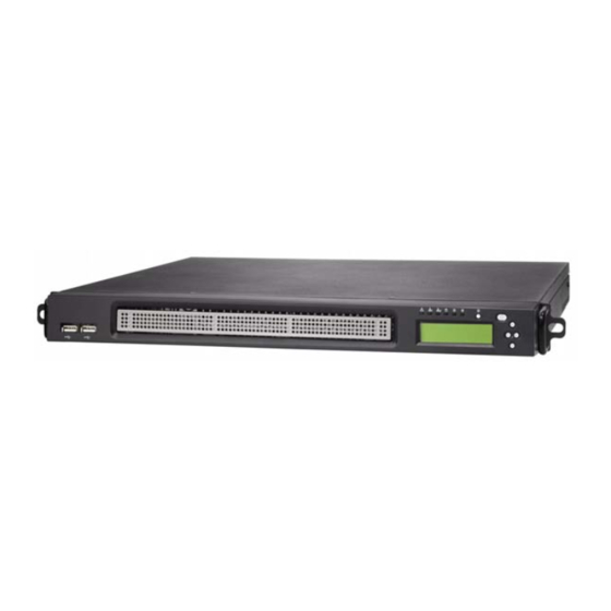
About the Product The following views show you the product. 1.5.1 Front View HDD Access LED LAN2 LED LAN1 LED ID LED Power LED Warning LED Power button LCD buttons ID button LCD Display 2 x USB ports 1.5.2 Rear View Power Supply Socket PCI-E Card PS/2 Mouse/Keyboard Ports... -
Page 16: Led Definition
1.5.3 LED Definition Front Panel Color State Description Power Green Power ON Power OFF HDD Access Amber Random Blink HDD access No disk activity LAN1/LAN2 Activity Green LAN linked Green Blinking LAN accessing No LAN linked Warning System fails (fan fail/ over voltage) Normal ID LED... -
Page 17: Internal View
1.5.4 Internal View FAN4 FAN3 FAN2 FAN1 1. M2082-2 PCI-E (or M2055 5. CPU sockets PCI-X) Riser card 6. Fans (Right to Left: Fan1, 2. Memory slots Fan2, Fan3, Fan4) 3. EPS Power supply 7. Front LED panel 4. Power connector 8. -
Page 18: Motherboard Block Diagram
1.5.5 Motherboard Block Diagram Chapter 1: Overview... -
Page 19: Motherboard Layout
1.5.6 Motherboard Layout Chapter 1: Overview... - Page 20 (CN4: CPU0 Fan / CN8: CPU1 Fan) CN9/CN10/ Chassis Fan Connectors CN13/CN14 (CN9: FAN2 / CN10: FAN1 / CN13: FAN3 / CN14: FAN4) CN11 Tyan SO-DIMM Connector CN12 Front Panel USB2.0 Connector CN15 COM2 Header CN19 Front Panel Header CN20...
-
Page 21: Chapter 2:Setting Up
Chapter 2: Setting Up 2.0.1 Before You Begin This chapter explains how to install the CPU, CPU heatsink, memory modules, and hard drives. Instructions on inserting a PCI-X card are also given. Take note of the precautions mentioned in this section when installing your system. -
Page 22: Precautions
2.0.4 Precautions Components and electronic circuit boards can be damaged by discharges of static electricity. Working on a system that is connected to a power supply can be extremely dangerous. Follow the guidelines below to avoid damage to the Tank GT14 or injury to yourself. •... -
Page 23: Installing Motherboard Components
Installing Motherboard Components This section describes how to install components on to the motherboard, including CPU, memory modules and a PCI-E card. 2.1.1 Removing the Top Chassis Cover Follow these instructions to remove the Tank GT14 top chas- sis cover. 1. -
Page 24: Installing The Cpu And Heatsink
2.1.2 Installing the CPU and Heatsink Follow these instructions to install the CPU and CPU heatsink. 1. Locate the CPU sockets. Start installing the CPU with CPU0 socket first. CPU0 CPU1 2. Take off the CPU protection cap. 3. Pull the CPU lever up to unlock the CPU socket. Chapter 2: Setting Up... - Page 25 4. Open the socket in the direction as shown. 5. Place the CPU in the CPU socket, ensuring that pin 1 is located as shown below. 6. Close the CPU socket cover and press the CPU socket lever down to secure the CPU. Chapter 2: Setting Up...
- Page 26 7. Place the heatsink on the top of the CPU and screw into place as shown. 8. Repeat these steps to install CPU and heatsink for the second CPU socket. Chapter 2: Setting Up...
-
Page 27: Installing The Memory
2.1.3 Installing the Memory Follow these instructions to install the memory modules on the motherboard. 1. Locate the memory slots on the motherboard. 2. Press the memory slot locking levers in the direction of the arrows as shown in the following illustration. Chapter 2: Setting Up... - Page 28 3. Align the memory module with the slot. The module has indentations that align with notches in the slots. 4. Insert the memory module into the slot as shown. See the memory population rules in the following table. When inserted properly, the memory slot locking levers lock automatically onto the indentations at the ends of the module.
-
Page 29: Installing The Pci-E Card
2.1.4 Installing the PCI-E Card Follow these instructions to install a PCI-E card. 1. Remove the screw securing the tab of PCI-X slot from the rear side of your GT14 B5372-LC-LC system. 2. Pull the tab of PCI-X slot on the rear side in the direction as shown to release the I/O shield. - Page 30 4. Insert the PCI-E card in the direction of arrows as shown. 5. Push the tab of PCI-X slot on the rear side in the direction as shown to secure the PCI-X card. 6. Secure the tab of PCI-X slot on the rear side with one screw as shown.
-
Page 31: Installing Dual 2.5" Hard Drives
Installing Dual 2.5” Hard Drives The GT14 chassis kit supports up to two internal SATA hard drives. Follow these instructions to install dual 2.5” internal hard drives. 1. Remove the screw securing the 2.5” drive bracket in the GT14 chassis. 2. - Page 32 3. Place the two 2.5” hard drives into the 2.5” drive bracket. Use 8 HDD screws to secure the hard drives. 4. Place the assembled hard drives with bracket in the spot you picked the 2.5” hard drive bracket from the GT14 chassis (A) and slide it into place (B).
- Page 33 6. Connect the two SATA power connectors to the hard drives. Then connect the hard drives to the motherboard using two supplied SATA cables. Chapter 2: Setting Up...
-
Page 34: Rack Mounting
Rack Mounting After installing the necessary components, the Tank GT14 can be mounted in a rack using the supplied rack mounting kit. The screw types are listed below for your reference. Screws List Rail for 4-post rack (Rail kit A) Item Screw Size... -
Page 35: Installing The Server In A Rack (With Rail Kit A)
2.3.1 Installing the Server in a Rack (with Rail kit A) Follow these instructions to mount the GT14 into an industry standard 19" rack. (Rail kit A) NOTE: Before mounting the Tank GT14 in a rack, ensure that all internal components have been installed and that the unit has been fully tested. - Page 36 3. Install inner rails to left and right sides of chassis using 1 M4-4L(A) screw for each side. Chapter 2: Setting Up...
- Page 37 Installing Outer Rails to the Rack 4. Measure the distance between inner side of the front and rear mounting brackets in the rack. 5. Reserve the distance same as in step 4 on rear racket. Secure the rear bracket to outer rail with 2 M4-4L(A) screws.
- Page 38 Rackmounting the Server 7. Draw out the middle rails to the latch position. 8. Lift the chassis and then insert the inner slide rails into the middle rails. 9. Push the chassis in and press the latch key (A). Then push the whole system into the rack (B).
- Page 39 10. Secure the mounting ears of chassis to the rack with one M4-15L(F) screw for each side. NOTE: To avoid injury, it is strongly recommended that two people lift the GT14 into the place while a third per- son screws it to the rack. Chapter 2: Setting Up...
-
Page 40: Installing The Server In An Open Rack (With Rail Kit B)
2.3.2 Installing the Server in an Open Rack (with Rail kit B) In addition to rackmounting the GT14 in a 4-post rack, you can also mount it in a 2-post rack. You must use rail kit B to mount the GT14 in this type of rack. 2-post open rack NOTE: Before mounting the Tank GT14 in a rack, ensure that all internal components have been installed and that the unit... - Page 41 2. Lift the chassis and secure the mounting brackets to the front of rack using 3 M5-8L(D) screws for each side. NOTE: To avoid injury, it is strongly recommended that two people lift the GT14 into the place while a third per- son screws it to the rack.
- Page 42 4. Slide the mounting brackets into the rear of inner rail brackets as shown. 5. Secure the mounting brackets with three M4-4L(E) screws for each side. 6. The GT14 has been mounted to the rack as shown. Chapter 2: Setting Up...
-
Page 43: Lcd Software Setup
IP address assigned to the system • Subnet mask of your network’ 2.4.2 M1000 Driver Installation for Windows Step 1. Install TYAN TSM program. Step 2. Install M1000 driver for Windows. 2.4.3 M1000 Driver Installation for Linux Step 1. Install M1000 driver for Linux... -
Page 44: Lcd Console
4. Down: Go to the next selection. After you have installed the TYAN TSM and M1000 driver for Windows (for Windows OS) or the M1000 driver for Linux (for Linux OS), you can use the LCD front panel control but- tons to get access to the information under each submenu. -
Page 45: Dos Mode And Windows Mode
2.5.2 DOS Mode and Windows Mode M1000 supports both DOS Mode and Windows Mode. DOS Mode BIOS Info Model Name DOS Mode Peripheral Device CPU Info RAM Info Item Screen Display BIOS Info V0.08.B10 memory Init. Model Name Tank GT14 −... - Page 46 Windows Mode Performance Memory Hard Disk Net Interface System Sensors Voltage Temperature Power Down Power Ctl Reboot Item Screen Display TYAN Computer Host Name GT14 B5372-LC System Nics NIC0 DHCP IP Address: xx.xx.x.xxx Net Mask: xxx.xxx.xxx.0 Gateway: xxx.xxx.xxx.0 NIC1 DHCP IP Address: xx.xx.x.xxx...
- Page 47 Item Screen Display TYAN Computer Host Name GT14 B5372-LC Performance CPU Usage x.xx% Memory Memory Usage Harddisk Disk Usage xx.xx% Net Interface NIC0 Flow Speed x Bps NIC1 Flow Speed x Bps System Sensors System Fan1 xxxxRPM System Fan2 xxxxRPM...
-
Page 48: Linux Mode
Linux Mode Performance Memory Hard Disk Net Interface System Sensors Voltage Temperature Power Down Power Ctl Reboot Item Screen Display TYAN Computer Host Name GT14 B5372-LC System Nics NIC0 DHCP IP Address: xx.xx.x.xxx Net Mask: xxx.xxx.xxx.0 Gateway: xxx.xxx.xxx.0 NIC1 DHCP IP Address: xx.xx.x.xxx... - Page 49 Item Screen Display TYAN Computer Host Name GT14 B5372-LC Performance CPU Usage x.xx% Memory Memory Usage Harddisk Disk Usage xx.xx% Net Interface NIC0 Flow Speed x Bps NIC1 Flow Speed x Bps System Sensors System Fan1 xxxxRPM System Fan2 xxxxRPM...
- Page 50 Chapter 2: Setting Up...
-
Page 51: Chapter 3:Replacing Pre-Installed Components
Chapter 3: Replacing Pre-Installed Components Introduction This chapter explains how to replace pre installed components including the motherboard, LCD module, LED board, cooling fans, and power supply. Take note of the precautions in this section when installing your system. 3.1.1 Work Area Make sure you have a stable, clean working environment. -
Page 52: Precautions
3.1.3 Precautions Components and electronic circuit boards can be damaged by static electricity. Working on a system that is connected to a power supply can be extremely dangerous. Follow the guidelines below to avoid damage to the Tank GT14 or injury to yourself. -
Page 53: Disassembly Flowchart
Disassembly Flowchart The following flowchart outlines the disassembly procedure. Rear Components DIMMs Chassis rear cover CPU/heatsink assembly Mainboard PCI-E card Power supply Mainboard Front Components Chassis rear cover PCBs LCD Module Front I/O Board USB Board Chapter 3: Replacing Pre-Installed Components... -
Page 54: Removing The Top Chassis Cover
Removing the Top Chassis Cover Before replacing any parts you must remove the top chassis cover. Follow these instructions to remove the Tank GT14 top chas- sis cover. 1. Remove the screw on the back side and two on the top of the top chassis cover. -
Page 55: Replacing Motherboard Components
Replacing Motherboard Components Follow these instructions to replace motherboard components, including the motherboard. 3.4.1 Disconnecting All Motherboard Cables Before replacing the motherboard or certain components, remove cables connected to the motherboard. Follow these instructions to remove all motherboard cabling. 1. Disconnect power cables. Main power EPS 12V power connector connector... -
Page 56: Removing The Motherboard
3.4.2 Removing the Motherboard After removing all of the aforementioned cables, follow these instructions to remove the motherboard from the chassis. 1. Remove the seven screws securing the motherboard to the chassis. 2. Remove the motherboard. Chapter 3: Replacing Pre-Installed Components... -
Page 57: Replacing The Lcd Module And Led Board
Replacing the LCD Module and LED Board Follow these instructions to replace the LCD module in your GT14 B5372-LC system. 1. Remove the chassis front cover as shown. 2. Remove the two screws securing to the LCD module. 3. Disconnect the LCM and control board cables. Chapter 3: Replacing Pre-Installed Components... - Page 58 4. Remove the four screws on both sides of the LCD module. 5. Remove the LCD front bracket from the LCD module. 6. Remove the two screws from the rear LCD bracket. Chapter 3: Replacing Pre-Installed Components...
- Page 59 7. Remove the three screws securing the LED board to the rear LCD bracket. Remove the LED board. 8. Place a new LCD module in position in the chassis following the above steps in reverse. Chapter 3: Replacing Pre-Installed Components...
-
Page 60: M1000 Lcd Module Features
3.5.1 M1000 LCD Module Features J3 2x3 pin header 3.5.2 M1017 LED Board Features Front View J1 2x14 pin header Rear View Warning LED LAN1 LED LAN2 LED ID Button Power Button HDD Access LED Power LED ID LED Chapter 3: Replacing Pre-Installed Components... -
Page 61: M1017 Led Board Connector Pin Definition
3.5.3 M1017 LED Board Connector Pin Definition J1 (2 x 14 Pin Header) HD_LED+ HD_LED- PW_LED+ WARN_LED+ WLED- PCI_SMBUSDA PCI_SMBUSCL FP_NMI_L NMI_PWR INTRUDER_L PWRSW- LAN1_LED+ LAN1_LEDLINK LAN2_LED+ LAN2_LEDLINK IDLED+ ID_LED- IDLEDBTN- ID_SW- Chapter 3: Replacing Pre-Installed Components... -
Page 62: Replacing The Usb Board
Replacing the USB Board Follow these instructions to replace the USB board in your GT14 B5372-LC system. 1. Remove the chassis front cover as shown. 2. Disconnect the USB cable from the USB board. 3. Remove the two screws securing the USB board to separate the USB board from the chassis. -
Page 63: Usb Board Features
4. Place a new USB board in position in the chassis following the above steps in reverse. 3.6.1 USB Board Features USB 2x5 pin Header USB1 USB2 3.6.2 USB Board Connector Pin Definition 2 x 5 Pin USB Header USB1 POWER USB2 POWER USB1 DATA - USB2 DATA -... -
Page 64: Replacing The Cooling Fans
Replacing the Cooling Fans Follow these instructions to replace the cooling fans in your GT14 B5372-LC system. 1. Disconnect the fan cable connectors from the fans and the motherboard. 2. Remove the fan unit from the chassis. 3. Remove the fan you want to replace in the direction of the arrow from the fan cradle. -
Page 65: Replacing The Power Supply
Replacing the Power Supply Follow these instructions to replace the power supply in your GT14 B5372-LC system. 1. Remove the top chassis cover. See “3.3 Removing the Top Chassis Cover” on page 46 for more details. 2. Detach the power cables from the motherboard. See “3.4.1 Disconnecting All Motherboard Cables”... - Page 66 4. Remove the two screws securing the power supply to the chassis. 5. Lift the power supply free from the chassis. 6. Replace a new power supply into the chassis following the above steps in reverse. 7. Remove the two screws that secure the power supply front breaket.
-
Page 67: Appendix I: Bios Differences
Appendix I: BIOS Differences The BIOS of B5372-LC is similar to the BIOS of S5372. How- ever, there is something different. You may refer to the attached motherboard manual for the complete BIOS infor- mation. The difference between B5372-LC and S5372 is on the submenu “Hardware Health Configuration”... - Page 68 PhoenixBIOS Setup Utility Advanced Item Specific Help Auto Fan Control [Disabled] Auto Mode Fan Control Parameters CPU0 Fan header [4 Pins CPU1 Fan header [4 Pins Front Fan1 header [4 Pins Front Fan2 header [4 Pins F1 Help Select Item -/+ Change Values F9 Setup Defaults Esc Exit...
- Page 69 PhoenixBIOS Setup Utility Advanced Item Specific Help Auto Fan Control [Disabled] Auto Mode Fan Control Parameters F1 Help Select Item -/+ Change Values F9 Setup Defaults Esc Exit Select Menu Enter Select F10 Save and Exit Sub-Menu Table of Differences S5372-LC B5372-LC-LC Auto Fan Power...
-
Page 70: Appendix Ii: Cable Connection Tables
Appendix II: Cable Connection Tables SATA Cable Table 1: GT14 B5372-LC Model Connect to Motherboard HDD 1 SATA 0 HDD 2 SATA 2 FAN Cable Table 2: System Fan to Motherboard System Fan Connect to Motherboard Fan 1 Fan 2 Fan 3 CN14 Fan 4... - Page 71 Other Cables Table 4: M1017 LED Board to Motherboard M1017 LED Board Connect to Motherboard CN19 CN22 Table 5: USB Board to Motherboard USB Board Connect to Motherboard USB 2x5 pin header CN12 Table 6: LCD Module to Motherboard M1000 LCD Module Connect to Motherboard CN21...
-
Page 72: Appendix Iii: Installing The Smdc Card
Appendix III: Installing the SMDC Card The following provides you with the information on installing the M3291 SMDC card into your GT14 chassis. 1. Connect the 2x25 pin SMDC cable to M3291 as shown. 2. Remove the two screws as indicated below. 3. - Page 73 4. Align the SMDC plate holder with the secured stand-off screws and secure in place with two screws as shown. 5. Secure the SMDC card to the plate holder with three screws. 6. Connect the other end of SMDC cable to the SMDC connector (CN20) on the motherboard.
- Page 74 Cable Connection Table SMDC Card (M3291) Connects to Motherboard J1 connector CN20...
-
Page 75: Appendix Iv: Fru Parts Table
Appendix IV: FRU Parts Table Model Item Part Number Picture Quantity Description Number S5372G2NR- LC Dual S5372G2N Motherboard ® R-LC Intel Xeon LGA771 CCHA- GT14 1U Chassis Unit 432765400003 0220 chassis Chassis Top CCCV- GT14 Top 340765400001 Cover 0110 Cover Front Bezel Chassis CFBZ-... - Page 76 Model Item Part Number Picture Quantity Description Number Front Control M1017 Board CPCA- USB Board 0400 PCBA SMDC IPMI M3291 Card M2082-2- PCI-E Riser Card Riser Card PCI-X Riser M2055-RS Card LCM Module M1000-RS MODULE LCM Front CMPT- 340765400029 Front-Bracket 0090 with Button LCM Back...
- Page 77 Model Item Part Number Picture Quantity Description Number Front Control CCBL- 422766600001 Board Cable, 0723 950mm CCBL- USB Cable, 422766600006 0356 230mm CCBL- LCM Cable, 422766600002 0603 900mm Power Cable CCBL- 422766600005 (Y Type), 0467 230mm SATA Cable, CCBL- HS/180- 422766600003 0328 HS/180,...
- Page 78 Model Item Part Number Picture Quantity Description Number CEAR- Mounting Ear 340765400025 0120 GT14 CRAL- 340765400009 Standard Rail 0110 Rack for 4-post Mounting Parts GT14 Open CRBK- 452765400031 Rail for 2- 0030 post GT14 Dual CRAL- Rail for 4- 340765400010 0111 post with 2 barebones...
-
Page 79: Technical Support
(which can have expensive consequences). If these options are not available for you then Tyan Computer Corporation can help.Besides designing innovative and qual- ity products for over a decade, Tyan has continuously offered customers service beyond their expectations. - Page 80 RMA number should be prominently displayed on the outside of the shipping carton and the package should be mailed pre- paid. TYAN will pay to have the board shipped back to you. Tank GT14 B5372-LC Service Engineer’s Manual v1.0 Document part No. D1902-100...
Need help?
Do you have a question about the Tank GT14 B5372-LC and is the answer not in the manual?
Questions and answers