Table of Contents
Advertisement
Quick Links
Advertisement
Table of Contents

Related Manuals for TYAN GT62H-B7106


Summary of Contents for TYAN GT62H-B7106
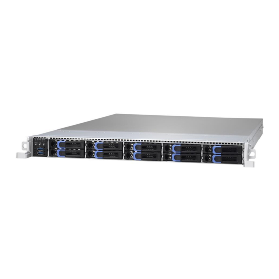
- Page 1 GT62H-B7106 Service Engineer’s Manual...
- Page 2 TECHNOLOGY CORPORATION and has been reviewed for accuracy and reliability prior to printing. MITAC assumes no liability whatsoever, and disclaims any express ® or implied warranty, relating to sale and/or use of TYAN products including liability or warranties relating to fitness for a particular purpose or merchantability. MITAC retains the right to make changes to produce descriptions and/or specifications at any time, without notice.
- Page 3 FCC Declaration ● Notice for the USA Compliance Information Statement (Supplier's Declaration of Conformity, SDoC) Part 15: This device complies with part 15 of the FCC Rules. This device complies with Part 15 of the FCC Rules. Operation is subject to the following conditions: ‧This device may not cause harmful interference.
- Page 4 Warning This equipment is compliant with Class A of CISPR 32. In a residential environment this equipment may cause radio interference. CAUTION Lithium battery included with this board. Do not puncture, mutilate, or dispose of battery in fire. There will be danger of explosion if battery is incorrectly replaced. Replace only with the same or equivalent type recommended by manufacturer.
- Page 5 How this guide is organized This guide contains the following parts: Chapter 1: Overview This chapter provides an introduction to the TYAN GT62H-B7106 barebones and standard parts list, describes the external components, gives an overview of the product from different angles.
- Page 6 Safety and Compliance Information Before installing and using TYAN GT62H-B7106, take note of the following precautions: ·Read all instructions carefully. ·Do not place the unit on an unstable surface, cart, or stand. ·Do not block the slots and opening on the unit, which are provided for ventilation.
- Page 7 You must become familiar with the safety information in this guide before you install, operate, or service TYAN products. Symbols on Equipment Caution. This symbol indicates a potential hazard.
- Page 8 · Make sure the stabilizing feet are attached to the rack if it is a single-rack installation. · Make sure racks are coupled together if it is a multiple-rack installation. · Make sure the rack is level and stable before installing an appliance in the http://www.tyan.com...
- Page 9 · Use only the power cords and power supply units provided with your system. The system might have one or more power cords. · Plug the power cord into a grounded (earthed) electrical outlet that is easily accessible at all times. http://www.tyan.com...
- Page 10 TYAN, your authorized TYAN partner, or their agents. Equipment Modifications · Do not make mechanical modifications to the system. TYAN is not responsible for the regulatory compliance of TYAN equipment that has been modified.
- Page 11 – Liquid has been spilled on the product or an object has fallen into the product. – The product has been exposed to rain or water. – The product has been dropped or damaged. – The product does not operate normally when you follow the operating instructions. http://www.tyan.com...
-
Page 12: Table Of Contents
Table of Contents Chapter 1: Overview ................ 15 About the TYAN GT62H-B7106 ..........15 Product Model ................ 15 Features.................. 16 Standard Parts List ..............20 1.4.1 Box Contents ..............20 1.4.2 Accessories ..............20 About the Product ..............21 1.5.1 System Front View ............ - Page 13 List ..................... 79 Appendix III: Cable Connection Tables ......... 80 Appendix IV: Fan and Temp Sensors ..........83 Appendix V: PSU sensor and PSU FAN spec ....... 87 Appendix VI: FRU Parts Table ............88 Appendix VII: Technical Support ............ 90 http://www.tyan.com...
- Page 14 NOTE http://www.tyan.com...
-
Page 15: Chapter 1: Overview
Leveraging advanced technology from ® Intel , GT62H-B7106 server system is capable of offering scalable 32 and 64-bit computing, high bandwidth memory design, providing a rich feature set and incredible performance, and lightning-fast PCI-E bus implementation. The GT62H-B7106 not only empowers your company in nowadays IT demand but also offers a smooth path for future application usage. -
Page 16: Features
Hot-swap Q'ty / Socket Type (2) LGA3647 Supported CPU Intel Xeon Scalable Processor Series Thermal Design Processor Max up to 165W Power (TDP) Wattage Up to 10.4/9.6 GT/s with Intel System Bus UltraPath Interconnect (UPI) support Chipset Intel C621 http://www.tyan.com... - Page 17 PCI-E (2) PCI-E Gen3 x16 slots (HH, HL) (1) M7106-R16-1F riser card for (1) PCI-E Gen3 x16 slot Pre-install TYAN (1) M2095-L24-2E riser card (not Riser Card sold separately) (left) for (1) PCI-E Gen3 x16 slot + (2) OCuLink x4...
- Page 18 Hardware Monitor, SMBIOS 3.0/PnP/Wake on LAN, Boot from BIOS USB device/PXE via LAN/Storage, Feature User Configurable FAN PWM Duty Cycle, Console Redirection, ACPI sleeping states S4,S5, ACPI 6.1 Please refer to our AVL support Operating System OS supported list lists. http://www.tyan.com...
- Page 19 In/Non-operating 90%, non-condensing at 35° C Humidity RoHS RoHS 6/6 Compliant Barebone (1) GT62H-B7106 Barebone Package Contains Manual (1) Quick Installation Guide NOTE: 1. The specifications are subject to change without prior notice. 2. Please visit our website for the latest specifications.
-
Page 20: Standard Parts List
Standard Parts List This section describes GT62H-B7106 package contents and accessories. Open the box carefully and ensure that all components are present and undamaged. The product should arrive with packaged as illustrated below. 1.4.1 Box Contents If any items are missing or appear damaged, contact your retailer or browse to TYAN’s website for service:... -
Page 21: About The Product
Access Green Access / Green Blinking Linking / Green Off Link Green Off Link / Green Off Off Link LAN2 Access Green Access / Green Blinking Linking / Green Off Link Green Off Link / Green Off Off Link http://www.tyan.com... -
Page 22: System Rear View
Expansion Slots for Mezzanine Card D-sub VGA Port 1Gb RJ45 LAN3 from Realtek RTL8211E (dedicated for IPMI) Security screw hole. (Screw NOT included in the system.) ID LED State Color Description Blue System identified ID LED System not identified http://www.tyan.com... - Page 23 10/100/1000 Mbps LAN Link/Activity LED Scheme Left LED Right LED Link Green 10 Mbps Active Blinking Green Link Green Green 100 Mbps Active Blinking Green Green Link Green Amber 1000 Mbps (1 Gbps) Active Blinking Green Amber No Link http://www.tyan.com...
-
Page 24: System Top View
M1301G62H-BP12E-10 HDD Backplane Board (6) System fans Memory Slots CPU Sockets PCIe x16 slot (M2095-L24-2E, pre-installed) PCIe x16 slot (M7106-R16-1F, pre-installed) M7106V-4E NVMe OCP card M7106R-4E NVMe OCP card (2) Zippy M1R-2800K2 Power Supply* refer to appendix V M1623G62H-D-PDB Power Distribution Board http://www.tyan.com... -
Page 25: Board Image
1.5.4 Board Image S7106 This picture is representative of the latest board revision available at the time of publishing. The board you receive may not look exactly like the above picture. http://www.tyan.com... -
Page 26: Board Parts, Jumpers And Connectors
The board you receive may not look exactly like the above diagram. The DIMM slot numbers shown above can be used as a reference when reviewing the DIMM population guidelines shown later in the manual. For the latest board revision, please visit our web site at http://www.tyan.com. http://www.tyan.com... - Page 27 29. SSI 8-pin CPU1 Power Connector (PW2) 11. Rear ID LED (ID_LED1) 30. SSI 8-pin CPU0 Power Connector (PW1) 31. CPU0 PVCCP POWER OK LED 12. TYAN Module Header (DBG_HD1) (P0_PG_LED1) 13. Front Panel USB3.0 Header (USB3_FPIO1) 32. SYS_FAN 1 Header (SYS_FAN_1) 14.
-
Page 28: Block Diagram
1.5.6 Block Diagram S7106 Block Diagram NOTE: Please refer to Tyan S7106 User Guide for more MB details. http://www.tyan.com... -
Page 29: Chapter 2: Setting Up
Caution! To avoid damaging the motherboard and associated components, use torque force within the range kgf/cm (6.09 lb/in) on each mounting screw for motherboard installation. Do not apply power to the board if it has been damaged. http://www.tyan.com... -
Page 30: Precautions
Working on a system that is connected to a power supply can be extremely dangerous. Follow the guidelines below to avoid damage to GT62H-B7106 or injury to yourself. Ground yourself properly before removing the top cover of the system. -
Page 31: Installing Motherboard Components
CPUs, memory modules and add on cards. 2.1.1 Removing the Chassis Cover Follow these instructions to remove GT62H-B7106 chassis cover. Loosen the Thumb screw on the back side of the chassis as in the small diagram in a counterclockwise direction. -
Page 32: Installing The Cpu And Heatsink
Installing the CPU and Heatsink Follow the steps below on installing CPUs and CPU heatsinks. GT62H-B7106 has two CPU sockets. Align and install the processor on the carrier. Carefully flip the heatsink. Then install the carrier assembly on the bottom of the heatsink and make sure the gold arrow is located in the correct direction. - Page 33 A new heatsink comes with pre-applied thermal grease. Once the heatsink has been removed from the processor, you need to clean the processor and heatsink using an alcohol solvent. Then apply new thermal grease before reinstalling the heatsink. Take out the protection cap. http://www.tyan.com...
- Page 34 To secure the heatsink, use a T30 Security Torx to tighten the screws in a sequential order (1 2 3 4). When disassembling the heatsink, loosen the screws in reverse order (4 3 2 1). http://www.tyan.com...
-
Page 35: Installing The Memory
2. Align the memory module with the slot. When inserted properly, the memory slot locking levers lock automatically onto the indentations at the ends of the module. Follow the recommended memory population table to install the other memory modules. http://www.tyan.com... - Page 36 Memory Population NOTE: The PCIE HOLDER should be removed before installing the MEMORY, otherwise it can’t be able to installed, especially the four yellow ones. http://www.tyan.com...
- Page 37 3. Populate the same DIMM type in each channel, specifically - Use the same DIMM size - Use the same # of ranks per DIMM 4. Always install with CPU0 Socket and DIMM_0 Slot first, following the alphabetical order. http://www.tyan.com...
- Page 38 3. Populate the same DIMM type in each channel, specifically - Use the same DIMM size - Use the same # of ranks per DIMM 4. Always install with CPU0 Socket and DIMM_0 Slot first, following the alphabetical order. http://www.tyan.com...
-
Page 39: Installing The Add-On Card
The following instructions are for Add-On card installation. You may refer to the procedures below for the installation. 1. Disconnect all the cables on the riser card bracket. 2. Unscrew the riser card bracket. 3. Take up the riser card bracket. http://www.tyan.com... - Page 40 4. Remove the PCI-E cover shields from the chassis. 5. Insert the PCI-E card in the direction of arrows as shown. http://www.tyan.com...
- Page 41 6. Screw the PCI-E cards firmly to the riser card bracket. http://www.tyan.com...
-
Page 42: Installing Hard Drives
2.1.5 Installing Hard Drives The GT62H-B7106 supports (10) 2.5” Hard Drives. Follow these instructions to install a hard drive. Located at the 2.5” HDD tray. Press the locking lever to release the 2.5” MVMe/ HDD tray Pull out the 2.5”SSD/ HDD tray. - Page 43 4. Remove the 4 screws to detach HDD tray bracket. 5. Place a hard drive into the drive tray. Use four screws to secure the HDD. Reinsert the HDD tray into the chassis. Press the locking lever to lock the 2.5”SSD/ HDD tray http://www.tyan.com...
-
Page 44: Rack Mounting
Rack mounting kit Sliding Rails x 2 Mounting Ears (including screws) x 2 Installing the Server in a Rack Follow these instructions to mount the TYAN GT62H-B7106 into an industry standard 19" rack. Screws List Screw Size Quantity... -
Page 45: Installing The Server In A Rack
19" rack. NOTE: Before mounting the TYAN GT62H-B7106 in a rack, ensure that all internal components have been installed and that the unit has been fully tested. However, to make the installation easier, we suggest that you remove all HDD trays before you insert the chassis into the rack. - Page 46 Pull the inner sliding rail forward to secure it to the chassis. Screw the mounting ear to each side of TYAN GT62H as shown using two screws of #6-32 L5.3 (B) from the supplied screws kit. The installation of the inner rail has completed.
-
Page 47: Installing The Outer Rails To The Rack
2.2.3 Installing the Outer Rails to the Rack Stuck the outer rail to the rack for each side. 2.2.4 Rack mounting the Server Lift the unit and then insert the inner slide rails into the middle rails. http://www.tyan.com... - Page 48 Secure the mounting ears of chassis to the rack with 2 M5x20L (A) screws. http://www.tyan.com...
- Page 49 NOTE http://www.tyan.com...
-
Page 50: Chapter 3: Replacing Pre-Installed Components
This chapter explains how to replace the pre-installed components, including the Motherboard, M1716-G75-FPB Front Panel Board, M1301G62H-BP12E-10 Backplane, M1623G62H-D-PDB Power Distribution board, M2095-L24-2E M7106-R16-1F Riser cards, System fan and Power supply unit etc. Disassembly Flowchart The following flowchart outlines the disassembly procedure. http://www.tyan.com... -
Page 51: Removing The Cover
Removing the Cover Before replacing any parts you must remove the chassis cover first. Follow Chapter 2.1.1 to remove the cover of the GT62H-B7106. Replacing Motherboard Components Follow these instructions to replace motherboard components, including the motherboard. 3.4.1 Disconnecting All Motherboard Cables Disconnect Mini SAS HD cables and power cables connected to the motherboard. - Page 52 Disconnect front panel cables, USB cable and Fan HD cables connected to the motherboard. http://www.tyan.com...
-
Page 53: Replacing The Riser Card
M7106-R16-1F Riser cards. 1. The GT62H-B7106 has preinstalled (2) riser cards. Release the 2 screw to lift the riser bracket from the chassis. Remove the screw of PCI-E bracket and lift up the bracket. 2. Remove the PCI-E cover shields from the chassis. - Page 54 3. Remove the 2 screws to release the M7106-R16-1F riser card. 4. Remove the 2 screws to release the M2095-L24-2E riser card. http://www.tyan.com...
-
Page 55: Riser Card Features
3.4.3 Riser Card Features M7106-R16-1F Riser Card M2095-L24-2E Riser Card (not sold separately) Location Definition PCIe X16 SLOT NVME0 OCU LINK Connector NVME1 OCU LINK Connector http://www.tyan.com... -
Page 56: Removing The Motherboard
After removing all of the aforementioned cables, follow the instructions below to remove the motherboard from the chassis. Remove the air duct, processor and heatsink if installed. Remove nine screws securing the motherboard to the chassis. Carefully lift the motherboard from the chassis. http://www.tyan.com... -
Page 57: Replacing The Front Panel Board
Replacing the Front Panel Board Follow these instructions to replace the M1716G75-FPB Front Panel Board. Unscrew the front panel tray. Pull the front panel tray forwards. Disconnect the control cable and USB3.0 cable from the front panel board. http://www.tyan.com... - Page 58 Unscrew the front panel board from the front panel tray for a new one. Reinstall the Front Panel Board into the chassis following the steps in reverse. http://www.tyan.com...
-
Page 59: Front Panel Board Features
Form Factor 28 x 35.4 x 1.6 (mm), 4-layer PCB I/O: (2) USB3.0 Port LED Indicators: (1) HDD LED (1) Warning LED Specifications (2) LAN LED (1) Power/ID LED Switch: (1) Reset Button (1) ID Button (1) Power Button http://www.tyan.com... -
Page 60: Connector Definition
3.5.2 Connector Definition Location Definition HDD_LED HDD LED BMC_EVENT_LED Warning LED LAN1_LED LAN1 LED LAN2_LED LAN2 LED ID_PW_LED Power/ID LED USB3.0 Port USB3.0 Port Reset Button ID Button Power Button Front Panel Control Board Connector USB3.0 Connector http://www.tyan.com... -
Page 61: Replacing The System Fan
Replacing the System Fan 1. GT62H-B7106 has equipment with system fans. Disconnect the fan cable which you need to replace up. 2. Take out the fan module from the chassis. http://www.tyan.com... - Page 62 3. Release the rubber screws and the push pins from the fan. 4. Replace the failed fan module with a new one. Follow the procedures described earlier in reverse order to reinstall. http://www.tyan.com...
-
Page 63: Replacing The Hdd Backplane Board
First pull the HDD trays slightly forwards to make the HDD BP Board easier to uninstall. Disconnect the power cables and SGPIO cables connected to the HDD Backplane. Disconnect the OCUlink cables connected to the HDD Backplane. http://www.tyan.com... - Page 64 Remove the four screws securing the bracket and lift the bracket. Remove the four screws securing the bracket and lift the bracket. Remove the eight screws to release the bracket to the HDD backplane. http://www.tyan.com...
-
Page 65: Hdd Backplane Features
(1) 8 Pin FAN connector (Power1) (1) 4Pin power connector connect to MB (2) 2x5 pin JTAG connector (1) 2x5 pin SGPIO connector connect to MB (J7) (10) Green LEDS for HDD activity LEDs (10) Red LEDS for HDD fault http://www.tyan.com... -
Page 66: Connector Definition
NVME 5 NVMe Connector NVME 6 NVMe Connector NVME 7 NVMe Connector NVME 8 NVMe Connector NVME 9 NVMe Connector SATA0_3 Mini SAS Connector OCULink Connector OCULink Connector OCULink Connector OCULink Connector OCULink Connector Power Connector 4X2P Power Connector 4X1P http://www.tyan.com... -
Page 67: Hdd Bp Board Led Definitions
3.7.3 HDD BP Board LED Definitions Color State Description Amber NVME/SATA HDD fail Status LED No failure found NVME/SATA HDD ready Green HDD Power/ Blinking NVME/SATA HDD access activity Active LED Power disconnected http://www.tyan.com... -
Page 68: Replacing The Power Distribution Board
Board in your system. Disconnect all cables connected to the power distribution board. Unscrew to take off the power distribution board and replace with a new one. Insert the PDB into the chassis following the above procedures in reverse. http://www.tyan.com... -
Page 69: Power Distribution Features
M1623G62H-D-PDB Front View Rear View PCB Dimensions: 420.4x36.7x2 MM (1) ATX 24 Pin Connector (3) ATX 8 Pin Connectors (2) HDD 4 Pin PWR Connector Integrated I/O (2) DOM 5V PWR (1) PMBUS (PW1) Power supply slots http://www.tyan.com... -
Page 70: Connector Definition
3.8.2 Connector Definition Location Definition Power supply slot Power supply slot PWR1 ATX Power 12x2 ATX Power 4x2 ATX Power 4x2 ATX Power 4x2 HDD Power 4x1 HDD Power 4x1 PMBUS DOM_5V_PW1 DOM Power DOM_5V_PW2 DOM Power http://www.tyan.com... -
Page 71: Replacing The Power Supply
Follow these instructions to replace the power supply module in your system. Press the latch to pull the power supply out. After replacing a new power supply, press and hold the latch to push the power supply back into the chassis. http://www.tyan.com... -
Page 72: Uninstalling Nvme Cards
3.10 Uninstalling NVMe Cards Follow these instructions to uninstalled the NVMe Cards. GT62H-B7106 equiped with two NVMe Cards,M7106R-4E/ M7106V-4E. Disconnect all the cable on the riser cards. Unscrew the riser card bracket. http://www.tyan.com... - Page 73 Remove the riser card bracket from the chassis. Disconnect the cables and use a screwdriver to unscrew the M7106R-4E NVMe card. Use a screwdriver to unscrew the M7106V-4E NVMe card. http://www.tyan.com...
-
Page 74: Power Distribution Features
3.10.1 Power Distribution Features M7106V-4E NVMe Card Front View Rear View Location Definition OCP Connector A OCP Connector B NVME01 OCULink Connector NVME23 OCULink Connector http://www.tyan.com... - Page 75 M7106R-4E NVMe Card Front View Rear View Location Definition OCP Connector A OCP Connector B NVMe01 OCU LINK Connector NVMe23 OCU LINK Connector Mini SAS HD EXT Connector http://www.tyan.com...
- Page 76 NOTE http://www.tyan.com...
-
Page 77: Appendix I: How To Recover Uefi Bios
UEFI recovery bootloader that would prevent the recovery process itself from working. In no event shall Tyan be liable for direct, indirect, incidental, special or consequential damages arising from the BIOS update or recovery. - Page 78 “Flash update completed. Press any key to reset the system” displayed on screen. Remove the USB disk and reboot. If your system does not have video output or the POST code halts at “FF” on the right-lower portion of the screen, please contact Tyan representatives for RMA service. http://www.tyan.com...
-
Page 79: Appendix Ii: Pcie Slot Location And Setup Items Corresponding
BIOS Setup: Socket Configuration>IIO PCIE PORT PCIE Slot Riser Type Reference on Configuration Location Socket0 IOU2(IIO 3A3B3C3D (7) PCIe M2095-L24-2E Configuration PCIe Br3) x16 slot 1.5.3 System Top View Socket1 IOU1(IIO 2A2B2C2D (8) PCIe M7106-R16-1F Configuration PCIe Br2) x16 slot http://www.tyan.com... -
Page 80: Appendix Iii: Cable Connection Tables
→ Cable (150mm) → B4P PWR Cable 3. Power Cable & PSMI Cable M1623G62H-D-PDB to S7106(MB) Cable M1623G62H Connect to S7106 2x4P PWR → Cable(350mm) 2x4P PWR → Cable(500mm) 2x12P PWR → PWR1 PWR1 Cable → PSMI Cable PSMI_HD1 http://www.tyan.com... - Page 81 → Chassis J121 Switch Cable 7. Oculink Cable (B7106G62HE10HR SKU) M1301G62H-BP12E-10 HDD BP to M7106R-4E OCP Card Cable M1301G62H Connect to M7106R-4E → Oculink Cable 5 NVME23 → Oculink Cable 4 NVME01 M1301G62H-BP12E-10 HDD BP to M2095-L24-2E Riser Card http://www.tyan.com...
- Page 82 Cable M1301G62H Connect to M2095 NVME0(P2) → Oculink Cable 3 NVME1(P1) M1301G62H-BP12E-10 HDD BP to M7106V-4E OCP Card Cable M1301G62H Connect to M7106V-4E → Oculink Cable 2 NVME23 → Oculink Cable 1 NVME01 http://www.tyan.com...
-
Page 83: Appendix Iv: Fan And Temp Sensors
(rpm) Temp Sensor: SYS_Air_Outlet (RT3) MB_Air_Inlet (RT2). They detect the system temperature around. NOTE: The system temperature is measured in a scale defined by Intel, not in Fahrenheit or Celsius. http://www.tyan.com... - Page 84 BIOS Temp Sensor Name Explanation: http://www.tyan.com...
- Page 85 http://www.tyan.com...
- Page 86 Fan speed of CPU0_FAN CPU1_FAN Fan speed of CPU1_FAN SYS_FAN_1 Fan speed of SYS_FAN_1 SYS_FAN_2 Fan speed of SYS_FAN_2 SYS_FAN_3 Fan speed of SYS_FAN_3 SYS_FAN_4 Fan speed of SYS_FAN_4 SYS_FAN_5 Fan speed of SYS_FAN_5 SYS_FAN_6 Fan speed of SYS_FAN_6 http://www.tyan.com...
-
Page 87: Appendix V: Psu Sensor And Psu Fan Spec
"When" PSU 0 or PSU 1 "is" removed unexpectedly or "got" damaged, the sensor table would still show the residual value of the last moment before PSU got shut down. Output Loading ZIPPY Fan Speed 9000±25% PSU FAN SPEC 15000±15% 100% 26500±10% http://www.tyan.com... -
Page 88: Appendix Vi: Fru Parts Table
SATA 6Gb/s, FRU-AS-9130 452T56500007 Tool-less Slide Rail Slide Rail Kit CEAR-0050 340740900010 Mounting Ear Kit FRU-CS-0330 332810000514 AC Power Cord, US type, 1800mm, CCBL-0300 332810000281 AC Power Cord; EU type, 1830MM Cable MINI-SAS HD to MiniSAS cable, FRU-CS-0870 422T56100001 700MM http://www.tyan.com... - Page 89 FRU-CS-0950 Vertical Oculink cable 80pin 422T60000001 422T60000002 FRU-CS-0960 Oculink cable 42pin x 2 http://www.tyan.com...
-
Page 90: Appendix Vii: Technical Support
MITAC serves multiple market segments with the industry’s most competitive services to support them. TYAN's tech support is some of the most impressive we've seen, with great response time and exceptional organization in general.” — Anandtech.com Please feel free to contact us directly for this service at tech-support@tyan.com... - Page 91 Return Merchandise Authorization (RMA) number. The RMA number should be prominently displayed on the outside of the shipping carton and the package should be mailed prepaid. TYAN will pay to have the board shipped back to you. ® GT62H-B7106 Service Engineer’s Manual V1.0d...
Need help?
Do you have a question about the GT62H-B7106 and is the answer not in the manual?
Questions and answers