Table of Contents
Advertisement
Quick Links
Advertisement
Table of Contents

Subscribe to Our Youtube Channel
Related Manuals for TYAN Transport GT20 B5350


Summary of Contents for TYAN Transport GT20 B5350
- Page 1 Transport GT20 B5350 Service Engineer’s Manual...
- Page 3 TYAN retains the right to make changes to product descriptions and/or specifications at any time, without notice. In no event will TYAN be held liable for any direct or indirect, incidental or consequential damage, loss of use, loss of data or other malady resulting from errors or inaccuracies of information contained in this document.
- Page 4 Federal Communications Commission (FCC) Notice for the USA Compliance Information State- ment (Declaration of Conformity Procedure) DoC FCC Part 15: This device complies with part 15 of the FCC Rules Operation is subject to the following conditions: 1) This device may not cause harmful interference, and 2) This device must accept any interference received including inter- ference that may cause undesired operation.
- Page 5 About this Manual This manual provides you with instructions on installing your Transport GT20. This manual is intended for experienced users and integrators with hardware knowledge of personal computers. This manual consists of the following parts Chapter 1: Provides an Introduction to the Transport GT20 B5350 bare-bones, packing list, describes the external components, gives a table of key compo- nents, and provides block diagrams of the system.
- Page 6 SAFETY INFORMATION Before installing and using the Transport GT20, take note of the fol- lowing precautions: – Read all instructions carefully. – Do not place the unit on an unstable surface, cart, or stand. – Do not block the slots and opening on the unit, which are pro- vided for ventilation.
-
Page 7: Table Of Contents
Table of Contents Chapter 1:Overview 1.1 About the Transport GT20 B5350 ......1 1.2 Product Models ........1 1.3 Features . - Page 8 3.7 Replacing the M1010 Adapter Board ..... . 46 3.7.1 M1010 Adapter Board Features for B5350 ... . 47 3.7.2 System Fan Layout .
-
Page 9: Chapter 1:Overview
Chapter 1: Overview About the Transport GT20 B5350 Congratulations on your purchase of the TYAN Transport GT20 (B5350), a highly-optimized rack-mountable barebone system. The Transport GT20 (B5350) offers the latest in dual processor server systems, providing a rich feature set and incredible performance. - Page 10 B5350G20S4H B5350G20S2H B5350G20S4 Chapter 1: Overview...
-
Page 11: Features
• Stacked two USB 2.0 ports • 8MB Frame Buffer of video memory • One 9-pin UART serial port Motherboard • One 15-pin VGA port • Tyan Tiger i7320 S5350G2NR-1U • Two RJ45 connectors system board Front Panel Features • ATX footprint (10.2”’ x 12”) •... - Page 12 • Five 40x40x28mm 15000rpm • System fan speed control and moni- heavy-duty fans toring • Two passive CPU heatsinks • Chassis intrusion alert • Supports Tyan Server Management Regulatory (TSM) • FCC Class B (Declaration of Con- Environment Temperature formity) •...
-
Page 13: Unpacking
If any items are missing or appear damaged, contact your retailer or browse to TYAN’s Web site for service: http://www.tyan.com. The Web site also provides information on other TYAN prod- ucts, plus FAQs, compatibility lists, BIOS settings, and more. 1 x Tyan driver CD... - Page 14 Barebone Manual Mainboard Manual Heatsink x 2 Rail Kit Sliding Rail x 2 & Bracket x 4 Mounting Bracket x 4 Screws Kit Chapter 1: Overview...
-
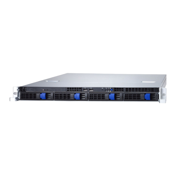
Page 15: About The Product
About the Product The following views show you the product. 1.5.1 Front View Reset switch Warning LED HDD activity LED Power LED *Reserved USB ports CD-ROM Drive Power switch LAN LEDs Hard Drive Bay x 4 *Reserved: reserved for future upgrade 1.5.2 Rear View Power Supply Socket Power Supply LED... -
Page 16: Led Definition
LAN access activity Warning 1. In DOS OS: Fan Fails 2. In Window OS: Fan Fails or System/CPU Overheat (Need to install Tyan TSM AP to get this feature. Users can use TSM to configure the warning condition.) Normal Hot Swappable HDD... - Page 17 RJ45 NIC2 Mode Amber Gigabit mode (Right Side) Green 100M mode 10M mode Delta Power Green Output ON and OK Supply LED Green 1Hz Blinking AC present/Only 5Vsb ON Amber Power supply critical event causing a shutdown: fail- ure, OCP, OVP, fan fail Amber 1Hz Blinking Power supply warning...
-
Page 18: Internal View
1.5.4 Internal View 1. PCI-X Slot 11. M8110 TARO SO-DIMM SATA card 2. Link Bar 12. SATA Cable 3. Memory Slots 13. CD-ROM Cable 4. Power Connectors 14. USB Cable 5. EPS 12V Power Supply 15. Four SATA HDDs 6. Air Duct 7. -
Page 19: Motherboard Block Diagram
1.5.5 Motherboard Block Diagram CPU0 VRD CPU1 VRD NOCONA NOCONA DDR 266/333 ECC REGISTERED DIMMs A HOST BUS 800 MEM CNTRL AND DATA PCI-EX 1 BCM5721 GLAN Intel E7320 MEM CNTRL AND DATA PCI-EX 1 BCM5721 GLAN HI 1.5 DDR 266/333 ECC REGISTERED DIMMs B PCI-X SLOT PRIMARY IDE CONN... -
Page 20: Motherboard Layout
1.5.6 Motherboard Layout CPUFAN1 FAN7 USB1 CPU1 (COM1) (VGA) LAN1 BATT CPU2 LAN2 Intel S5350 E7320 LED1 JP39 64-bit 66MHz PCI-X PCIX-P1 FAN6 FAN5 CPUFAN2 FAN4 SO_DIMM PCIX-P3 J19(Optional) RAGE XL FAN1 FAN3 JP25 FAN2 Intel JP24 6300ESB JP21 BIOS SMSC DME1737 JP18... - Page 21 Jumpers & Connectors Jumper Function /Connector SO-DIMM socket SMDC connector Front Panel connector Reserved External Speaker header Reserved Reserved FAN1/2/3/4/5 Chassis Fan Connectors with tachometer monitoring and fan speed control JP13 Front Panel USB Header CPUFAN1/2 CPU Fan Connectors with tachometer monitoring and fan speed control JP16 SATA activity LED header...
- Page 22 Memo Chapter 1: Overview...
-
Page 23: Chapter 2:Setting Up
Chapter 2: Setting Up 2.0.1 Before You Begin This chapter explains how to install the CPU, CPU heatsink, memory modules, and hard drives. Instructions on inserting a PCI card are also given. Take note of the precautions mentioned in this section when installing your system. -
Page 24: Precautions
2.0.4 Precautions Components and electronic circuit boards can be damaged by discharges of static electricity. Working on a system that is connected to a power supply can be extremely dangerous. Follow the guidelines below to avoid damage to the Transport GT20 or injury to yourself. •... -
Page 25: Rack Mounting
Rack Mounting The Transport GT20 can be mounted in a rack using the sup- plied rack mounting kit. Rack mounting kit Sliding Rails x 2: Sliding Rail Brackets x 4 Mounting Ears x 2 Mounting Brackets x 4 Screws Kit x 1 2.1.1 Installing the Server in a Rack Follow these instructions to mount the Transport GT20 B5350 into an industry standard 19"... - Page 26 2. Using two screws from the supplied screws kit to secure the sliding rail to the bracket. Sliding Rail & Bracke 3. Slide each sliding rail to the side of Transport GT20 as shown. 4. Using two screws from the supplied screws kit to secure the sliding rail to the side of Transport GT20.
- Page 27 5. Find the mounting bracket from the supplied kit and screw it to the rack using 2 screws on each side. Be care- ful that the mounting bracket should be secured from the inside of rack, not from the outside of rack. See the picture below for the correct direction.
- Page 28 6. Lift the unit into place in the rack (A). Ensure the unit is completely inserted into the rack (B). Then screw the unit into place as shown (C). Note: To avoid injury, it is strongly recom- mended that two people lift the Transport GT20 into place while a third per- son screws it to the rack.
-
Page 29: Installing Motherboard Components
Installing Motherboard Components This section describes how to install components on to the motherboard, including CPU, memory modules and PCI card. 2.2.1 Removing the Chassis Cover Follow these instructions to remove the Transport GT20 chassis cover. 1. Remove the screw on the back side. Then slide the chas- sis cover in the direction of arrow. -
Page 30: Installing The Cpu, Heatsink And Air Duct
2.2.2 Installing the CPU, Heatsink and Air Duct Follow these instructions to install the CPU, CPU heatsink and air duct. 1. Remove the pre-installed air duct. Then locate the CPU socket. CPU socket 2. Pull the CPU lever up to unlock the CPU socket. Chapter 2: Setting Up... - Page 31 3. Place the CPU on the CPU socket, ensuring that pin 1 is located in the right direction. 4. Press the CPU socket lever down in the direction shown to secure the CPU. Chapter 2: Setting Up...
- Page 32 5. Align the heatsink screw holes with the holes on the motherboard and insert heatsink screws in the orders as shown. 6. Place the air duct over the heatsink and secure the air duct to the motherboard using two screws. Chapter 2: Setting Up...
- Page 33 2.2.3 Installing the Memory Follow these instructions to install the memory modules on the motherboard. 1. Locate the memory slots on the motherboard. Memory slots 2. Press the memory slot locking levers in the direction of the arrows as shown in the following illustration. 3.
-
Page 34: Installing The Memory
4. Insert the memory module into the slot as shown. When inserted properly, the memory slot locking levers lock automatically onto the indentations at the ends of the module. NOTE: When installing memory, always install the memory beginning with DIMM4, not DIMM1. That means starting the installation from the memory module near the power supply. - Page 35 2. Move the bracket to right as shown and then take off the bracket. 3. Insert the PCI card in the directions of arrow as shown. 4. Push the tab of PCI slot on the rear panel in the direction as shown to fix PCI card.
-
Page 36: Installing The Hard Drive
Installing the Hard Drive The Transport GT20 barebone system supports Serial ATA hard drives. Follow these instructions to install a SATA hard drive. 1. Press the locking lever latch in the direction of arrow (A) and then pull the locking lever open (B). 2. - Page 37 4. Secure SATA hard drive using 4 screws 5. Reinsert the drive bay into the chassis (A), ensuring that the drive bay is completely inserted into the chassis (B). 6. Press the locking lever to secure the hard drive bay. Chapter 2: Setting Up...
-
Page 38: Installing The Slim Fdd (Option)
Installing the Slim FDD (Option) 1. Locate the two FDD rails and screws from the FDD kit. Secure the two rails to FDD using four screws. FDD Rails & Screws 2. Connect the FFC cable to FDD. 3. Using a screw driver to pull open the door of FDD tray. 4. - Page 39 5. Connect the FFC cable to the connector on M1010 adapter board. 6. Locate the FDD cable from FDD kit. Connect the wrinkle side to the connector on M1010 adapter board. Refer to the picture below for the correct direction. For Mainboard For M1010 7.
- Page 40 Memo Chapter 2: Setting Up...
-
Page 41: Chapter 3:Replacing Pre-Installed Components
Chapter 3: Replacing Pre-Installed Components Introduction This chapter explains how to replace pre installed compo- nents including the motherboard, LED control board, HDD, and CD-ROM drive. Take note of the precautions in this section when installing your system. 3.1.1 Work Area Make sure you have a stable, clean working environment. -
Page 42: Precautions
3.1.3 Precautions Components and electronic circuit boards can be damaged by static electricity. Working on a system that is connected to a power supply can be extremely dangerous. Follow the guidelines below to avoid damage to the Transport GT20 or injury to yourself. -
Page 43: Disassembly Flowchart
Disassembly Flowchart The following flowchart outlines the disassembly procedure. Rear Components DIMMs Chassis cover CPU/heatsink assembly Air duct PCI card Mainboard Mainboard Power supply Chassis cover PCBs CD-ROM Control M1010 Board Adapter Board HDD Backplane Chapter 3: Replacing Pre-Installed Components... -
Page 44: Removing The Cover
Removing the Cover Before replacing any parts you must remove the chassis cover. Follow these instructions to remove the cover of the Transport GT20 chassis cover. 1. Remove the screw on the back side. Then slide the chas- sis cover in the direction of arrow. 2. -
Page 45: Replacing Motherboard Components
Replacing Motherboard Components Follow these instructions to replace motherboard compo- nents, including the motherboard. 3.4.1 Disconnecting All Motherboard Cables Before replacing the motherboard or certain components, remove cables connected to the motherboard. Follow these instructions to remove all motherboard cabling. Main Power EPS 12V Power CPUFAN1 FAN7... - Page 46 1. Disconnect ATX power cables Main Power EPS 12V Power 2. Disconnect CD-ROM drive cable. Chapter 3: Replacing Pre-Installed Components...
- Page 47 3. Disconnect the cables from front panel, USB, chassis intrusion, LAN1 and LAN2 connectors. 4. Disconnect all of the fan cables. Chapter 3: Replacing Pre-Installed Components...
- Page 48 5. Follow the instructions below to disconnect the SATA card and SATA cable. A. Disconnect the SATA cable. B. Disconnect the SATA LED cables (B-1) and then remove the two screws as shown (B-2). C. Press the two edges in the directions of arrow to release the SATA card.
-
Page 49: Removing The Motherboard
3.4.2 Removing the Motherboard After removing all of those cables, follow these instructions to remove the motherboard from the chassis. 1. Remove the link bar. 2. Remove nine screws securing the motherboard to the chassis. 3. Remove the motherboard. Chapter 3: Replacing Pre-Installed Components... -
Page 50: Replacing The Slim Cd-Rom
Replacing the Slim CD-ROM Follow these instructions to replace the CD-ROM. 1. Remove power and data cables from the slim CD-ROM adapter. Power Cable Data Cable 2. Press the tab in the directions as show to release the CD- ROM drive. Chapter 3: Replacing Pre-Installed Components... - Page 51 3. The CD-ROM drive will be freed from the drive bay after pressing the tab. 4. Remove two screws that secure CD-ROM drive to the bracket. 5. Replace the CD-ROM drive. 6. Secure CD-ROM to the bracket using two screws. Then replace the unit into the drive bay and connect the CD- ROM power and data cables.
-
Page 52: Replacing The Led Control Board
Replacing the LED Control Board Follow these instructions to replace the LED control board. 1. Remove two screws securing LED control board unit to the chassis. 2. Lift the LED control board unit free of the chassis. 3. Unplug the ribbon cable from the connector. Chapter 3: Replacing Pre-Installed Components... - Page 53 4. Unplug the USB cable from the connector. 5. Remove three screws securing LED control board to the bracket 6. Lift the LED control board free from the chassis. After replacement, insert the unit into the chassis following the reverse procedures from step 1~4. Chapter 3: Replacing Pre-Installed Components...
-
Page 54: Replacing The M1010 Adapter Board
Replacing the M1010 Adapter Board 1. Remove all of those cables connected to the adapter board, including fan cables, CD-ROM power cable, front LED panel cable, power cables, and SATA cables. Refer to p.46 for the location. 2. Remove five screws to release the adapter board. Refer to p.46 for the location. -
Page 55: M1010 Adapter Board Features For B5350
3.7.1 M1010 Adapter Board Features for B5350 J14: Fan Tach Connector J1: Front Panel Connector FDD1 Connector J16: LCM Connector J7:Fan Tach & PWM Connector J3: LAN/ID LED Connector JP1: Fan Input Select Connector J19:CD-ROM Power Connector J5: Fan Connector J9: Fan Connector J11: Fan Connector J10: Fan Connector... -
Page 56: System Fan Layout
3.7.2 System Fan Layout The following picture provides the information for system fan layout. Refer to the tables on p.48 for information on connec- tion. Chapter 3: Replacing Pre-Installed Components... - Page 57 System Fan Speed Control Signal M1010 Adapter Board Connect to Motherboard J7 PWM Connector J20 PWM Signal System Fan Monitoring Signal Barebone System Fan Connect to Motherboard Fan Fan 1 (Fan J13) CPU Fan 1 Fan 2 (Fan J13) CPU Fan 2 Fan 3 (Fan J14) Fan 3 Fan 4 (Fan J14)
-
Page 58: M1010 Adapter Board Connector Pin Definition
3.7.3 M1010 Adapter Board Connector Pin Definition J1 TYFP Front Panel Connector HDLED+ PW_LED+ HDLED - PW_LED - RESET- PWR_SW+ RESET+ PWR_SW - VOLTAGE5 WLED+ EXT_INT WLED- V5SB KEY PIN ICH_SMBDAT ICH_SMBCLK INTRU# J2 Front Panel Connector HDLED+ HDLED- RESET+ RESET- PW_LED+ PW_LED-... - Page 59 J3 LAN/ID LED Connector LAN1_LED+ LAN1_LED- LAN2_LED+ LAN2_LED- LAN3_LED+ LAN3_LED- ID_LED+ ID_LED- ID_SW+ ID_SW- KEY PIN FAN Signal Related Connector Pin Definition NOTE: The FAN signal naming is based on HW circuit design only. It might be different from the system fan naming. J7 Fan TACH &...
- Page 60 J14 Fan TACH Connector FAN4_TACH FAN5_TACH FAN6_TACH FAN7_TACH FAN8_TACH FAN9_TACH FAN10_TACH KEY PIN J6 Fan Connector FAN1_12VPWM FAN1_TACH FAN2_TACH FAN2_12VPWM J10 Fan Connector FAN3_12VPWM FAN3_TACH FAN4_TACH FAN4_12VPWM Chapter 3: Replacing Pre-Installed Components...
- Page 61 J11 Fan Connector FAN5_12VPWM FAN5_TACH FAN6_TACH FAN6_12VPWM J9 Fan Connector FAN7_12VPWM FAN7_TACH FAN8_TACH FAN8_12VPWM J5 Fan Connector FAN9_12VPWM FAN9_TACH FAN10_TACH FAN10_12VPWM Chapter 3: Replacing Pre-Installed Components...
- Page 62 J15 & J16 LCM Connectors LCM_+5V LCM_SIN KEY PIN LCM_+5VSB LCM_SOUT JP1 Fan Input Select Connector Pin1 & Pin2 Close Fan PWM signal from J8 Pin2 & Pin3 Close Fan PWM signal from J7 Chapter 3: Replacing Pre-Installed Components...
-
Page 63: Replacing The Sata Backplane
Replacing the SATA Backplane 1. After removing the M1010 adapter board, disconnect those cables connected to the SATA backplane, including SATA and power cables. 2. Grab the two tabs to lift the SATA backplane off. 3. Remove ten screws that secure the bracket to the adapter board. - Page 64 4. Release the adapter board free from the bracket. 5. After replacement, place and secure the unit into the chassis following the reverse procedures from step 1 to Chapter 3: Replacing Pre-Installed Components...
-
Page 65: Sata Backplane Features
3.8.1 SATA Backplane Features U4, SATA 4 Connector U3, SATA 3 Connector U2, SATA 2 Connector HDD Power LED HDD Active LED U1, SATA 1 Connector Chapter 3: Replacing Pre-Installed Components... - Page 66 Power Connector J4, SATA 4 Connector J3, SATA 3 Connector J4, HDD Access J2, SATA 2 Connector LED Connector 1 JP1, HDD Access J1, SATA 1 Connector LED Connector 2 Chapter 3: Replacing Pre-Installed Components...
- Page 67 HDD Access LED Connector Pin Definition HD_ACCLED1+ HD_ACCLED1_N HD_ACCLED2+ HD_ACCLED2_N HD_ACCLED3+ HD_ACCLED3_N HD_ACCLED4+ HD_ACCLED4_N NOTE: This is a normal HDD access LED connector. It just passes through the LED signal from SATA controller. HD_ACCLED1+ HD_ACCLED1- HD_ACCLED2+ HD_ACCLED2- HD_ACCLED3+ HD_ACCLED3- HD_ACCLED4+ HD_ACCLED4- NOTE: This is a HDD access LED connector with reverse signal circuit design.
-
Page 68: Replacing The Power Supply
Replacing the Power Supply 1. Remove two screws securing the power supply to the chassis. 2. Remove the screw securing fan assembly to the chassis. Chapter 3: Replacing Pre-Installed Components... - Page 69 3. Lift the power supply free from the chassis. After replace- ment, place and secure the unit into the chassis following the reverse procedures from steps 1 to 2. Chapter 3: Replacing Pre-Installed Components...
- Page 70 Memo Chapter 3: Replacing Pre-Installed Components...
-
Page 71: Appendix I: Bios Differences
Appendix I: BIOS Differences The BIOS of B5350 is similar to the BIOS of S5350. However, there is something different. You may refer to the attached motherboard manual for the complete BIOS information. The difference between B5350 and S5350 is on the submenu “Integrated Monitor”... - Page 72 B5350 System BIOS PhoenixBIOS Setup-Copyright 1985-2001 Phoenix Technologies Ltd. Advanced Item Specific V+12 Help VBAT Vcpu1 Vcpu2 VCC= 3.3Vsb= V1.5= VTT= 5Vsb 3.3Vsb= Fan1 Fan2 Fan3 Fan4 Fan5 CPU1 Temp.= CPU2 Temp.= Ambient Temp1= Ambient Temp2= Ambient Temp3= Ambient Temp4= Auto Fan Control [Enabled] F1: Help...
-
Page 73: Appendix Ii: Cable Connection Tables
Appendix II: Cable Connection Tables SATA Cable Table 1: B5350G20S4H Model M1204 SATA Backplane Connect to M8110 Card SATA 1 SATA 0 SATA 2 SATA 1 SATA 3 SATA 2 SATA 4 SATA 3 Table 2: B5350G20S2H Model M1204-2 SATA Backplane Connect to Motherboard SATA 1... - Page 74 Table 4: M1010 Adapter Board to Motherboard J14 Fan 3 cable Fan 3 J14 Fan 4 cable Fan 4 J14 Fan 5 cable Fan 5 J7 PWM cable J20 PWM header Power Supply Cable Table 5: Power Supply to Motherboard Power Supply Connect to Motherboard...
- Page 75 The Other Cable Table 8: M1010 Adapter Board to Motherboard M1010 Connect to M1204 J3 LAN1 LED cable JP21 J3 LAN2 LED cable JP30 J1 Front Panel connector J22 TYFP(1~14pin) Table 9: M1003 Front Panel Control Board Related Cable M1003 J1 USB connector Motherboard JP13 USB2 M1003 J2 connector M1010 J2 connector...
-
Page 76: Technical Support
(which can have expensive consequences). If these options are not available for you then Tyan Computer Corporation can help.Besides designing innovative and qual- ity products for over a decade, Tyan has continuously offered customers service beyond their expectations. - Page 77 RMA number should be prominently displayed on the outside of the shipping carton and the package should be mailed pre- paid. TYAN will pay to have the board shipped back to you. Transport GT20, B5350 Service Engineer’s Manual v1.01 Document part No. D1641-100...
Need help?
Do you have a question about the Transport GT20 B5350 and is the answer not in the manual?
Questions and answers