Table of Contents
Advertisement
Quick Links
Advertisement
Table of Contents

Subscribe to Our Youtube Channel
Related Manuals for TYAN Transport GT26-B4987


Summary of Contents for TYAN Transport GT26-B4987
- Page 1 Transport GT26 B4987 Service Engineer’s Manual...
-
Page 3: Table Of Contents
Table of Contents Chapter 1: Overview 1.1 About the Transport GT26 B4987…………………….……...…….… 1 1.2 Product Models…………………..……………………….………..2 1.3 Features……………………………………………………………….. 3 1.4 Unpacking………………………………….……..………....5 1.4.1 Box Contents……………………...…………………………………… 1.4.2 Accessories…………………………………………………………….. 1.5 About the Product……….………………………..……....... 9 1.5.1 System Front View…………………………..………………………… 1.5.2 System Rear View…………………………………....... 1.5.3 Internal View…………………………………………………………... - Page 4 3.6.2 M1003 LED Control Board Connector Pin Definition………………… 55 3.7 Replacing the M1221 HDD and FAN backplane………..…….... 3.7.1 M1221 HDD and FAN backplane Features for B4987……....57 3.7.2 System Fan Layout……………………………………………....58 3.7.3 M1221 HDD and FAN backplane Connector Pin Definition..………… 59 3.8 Replacing the Power Supply……..…………........
- Page 5 TYAN retains the right to make changes to product descriptions and/or specifications at any time, without notice. In no event will TYAN be held liable for any direct or indirect, incidental or consequential damage, loss of use, loss of data or other malady resulting from errors or inaccuracies of information contained in this document.
-
Page 6: Notice For Canada
Federal Communication Commission (FCC) Notice for the USA Compliance Information Statement (Declaration of Conformity Procedure) DoC FCC Part 15: This device complies with part 15 of the FCC Rules Operation is subject to the following conditions: This device may not cause harmful interference; This device must accept any interference received including interference that may cause undesired operation. -
Page 7: About This Manual
About this Manual This manual provides you with instructions on installing your Transport™GT26-B4987. This Manual is intended for experienced users and integrators with hardware knowledge of personal computers. This manual consists of the following parts: Chapter1: Provides an introduction to the GT26 B4987 barebones, packing list, describes the external components, gives a table of key components, and provides block diagrams of... -
Page 8: Safety Information
SAFETY INFORMATION Before installing and using the Transport™GT26-B4987, take note of the following precautions: – Read all instructions carefully. – Do not place the unit on an unstable surface, cart, or stand. – Do not block the slots and opening on the unit, which are provided for ventilation. -
Page 9: Chapter 1: Overview
TYAN is also proud to deliver the Transport™ GT26 B4987 in SATAII/SAS flavor while supporting up to three (3) hot-swap hard drives and one (1) slim ODD. The Transport™ GT26 B4987 uses TYAN’s latest chassis featuring a robust... -
Page 10: Product Models
Product Models Supported HDD With IB Model Power supply type & quantity Onboard B4987G26W3H SAS(3), Hot-swappable 1000W single B4987G26W3HI SAS(3), Hot-swappable 1000W single Chapter 1: Product Overview... -
Page 11: Features
Features Enclosure Back I/O Ports • Industry 19” rack-mountable 1U • Stacked PS/2 Mouse & Keyboard chassis ports • COM1 connector (1) slim ODD bay • (1) One 15-pin VGA port (3) 3.5” HDD bays • Dimension: • (2) USB2.0 ports •... - Page 12 Conformity) • CE (Declaration of Conformity) (TSM) • VCCI • Watch Dog Timer supported • C-Tick • Support TYAN M3295 SMDC Card Environment Temperature Networking • Operating temperature: 5°C ~ 35°C • Dual Gigabit Ethernet ports • Non-operating temperature: -40°C (Marvell88E1121 Gigabit PHY) •...
-
Page 13: Unpacking
1.4.1 Box Contents Component Description Industry standard 1U chassis, (3) hot-swap HDD bays Tyan S4987 system board (pre-installed) Air Duct 1 x slim ODD drive (pre-installed) M1003: LED and USB control board (pre-installed) Chapter 1: Product Overview... - Page 14 1000W Single Power (7) System fans (40mm x 40mm x 56mm) M1221 HDD and FAN Backplane M4987-HTX (Optional parts) M2061 PCI-E to PCI-X (Optional parts) M2083 (pre-installed) Chapter 1: Product Overview...
-
Page 15: Accessories
If any items are missing or appear damaged, contract your retailer or browse to TYAN’s website for service: http://www.tyan.com The Web site also provides information on other TYAN products, plus FAQs, compatibility lists, BIOS settings, and more. 1 x Tyan Barebone Drive CD... - Page 16 Rail Kit Mounting Bracket x 4 Screw Kit Sliding Brackets Sliding Rail x 2 Front L-Bracket x 2 Rear L-Bracket x 2 Chapter 1: Product Overview...
-
Page 17: About The Product
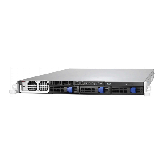
About the Product The following views show you the product. 1.5.1 System Front View Reset Switch Warning LED HDD Activity LED NMI Switch Power LED ID Switch ID LED USB Ports Power Switch 2 x LAN LEDs ODD Drive Power Supply Hard Drive Bay x 3 1.5.2 System Rear View... -
Page 18: Front Panel
LED Definition Front Panel Color State Description Green Power ON Power Power OFF Amber Random Blinking HDD access activity HDD Activity No disk activity Green LAN Linked Green Blinking LAN Accessing LAN1/LAN2 Linkage No LAN link Fan failure(<1500RPM) Over Temperature(90℃) Warning Voltage failure (+/-10%) Normal... - Page 19 Rear I/O LED Color State Description Green LAN Linked OPMA NIC Linkage Green Blinking LAN Accessing (Left Side) No LAN link OPMA NIC Mode Green 100M mode (Right Side) 10M mode Green LAN Linked RJ45 NIC1 Linkage Green Blinking LAN Accessing (Left Side) No LAN link Amber...
-
Page 20: Internal View
1.5.3 Internal View 1. CPU0 Memory Slots 9. M1221 2. CPU0 10. LED Control Board Cable 3. CPU2 Memory Slots 11. Three SATA/SAS HDD Bays 4. CPU2 12. Power Supply 5. CPU3 Memory Slots 13. USB Cable 6. CPU3 14. SAS Connectors 7. -
Page 21: Motherboard Layout
1.5.4 Motherboard Layout This diagram is representative of the latest board revision available at the time of publishing. The board you receive may not look exactly like the above diagram. Chapter 1: Product Overview... -
Page 22: Jumpers & Connectors
1.5.5 Jumpers & Connectors Jumper/Connector Function Front Panel Header (14Pin x 2) IPMB Pin Header (4Pin x 1) USB Pin Header (5Pin x 2) LCM Pin Header (3Pin x 2) FAN Tach Connector (9Pin x 2) M2061 PWR Connector (4Pin x 1) J36/J37 SAS SGPIO Connector (3Pin x 2) SAS Fault LED Connector (5Pin x 2) - Page 23 Jumper Placement PWR6 J3: Front Panel Connector (14Pin x 2) Signal Signal HD LED+ HD LED- Reset Button+ Reset Button- PW LED+ PW LED- Fault LED+ Fault LED- SM BUS DATA SM BUS CLK NMI Button NMI Button- 5VSB INTRUDER# PWR Button+ PWR Button- LAN2 LED+...
- Page 24 J5: IPMB Pin Header (4Pin x 1) Signal Signal IPMB DATA IPMB CLK J12: USB Pin Header (5Pin x 2) Signal Signal +5VPWR +5VPWR DATA1- DATA2- DATA1+ DATA2+ Use this header to connect to the USB devices via the enclosed USB cable. J18: LCM Pin Header (3Pin x 2) Signal Signal...
- Page 25 J36/J37 J35: M2061 PCI-E to PCI-X Riser Connector (4Pin x 1) Signal VDD_5_RUN Pin_1 J36/J37: SAS SGPIO Connector (3Pin x 2) Signal Signal SAS_SIO_DIN SAS_SIO_DOUT SAS_SIO_CLK KEY PIN SAS_SIO_END Chapter 1: Product Overview...
- Page 26 SAS_FAULT_L KEY PIN ED_N7 SAS_FAULT_L ED_N6 JP3/JP4: OPMA Setting Jumper (2Pin) Install: TYAN OPMA Card (Default) Remove: Other OPMA Card JP8: COMS Clear You can reset the CMOS settings by using this jumper if you have forgotten your Pin_3 Pin_1...
-
Page 27: System Block Diagram
1.5.6 System Block Diagram Chapter 1: Product Overview... -
Page 28: Chapter 2: Setting Up
Chapter 2: Setting Up 2.0.1 Before you Begin This chapter explains how to install the CPU, CPU heatsink, memory modules, and hard drives. Instructions on inserting PCI card and HTX card are also given. 2.0.2 Work Area Make sure you have a stable, clean working environment. Dust and dirt can get into components and cause malfunctions. -
Page 29: Precautions
2.0.4 Precautions Components and electronic circuit boards can be damaged by discharges of static electricity. Working on a system that is connected to a power supply can be extremely dangerous. Follow the guidelines below to avoid damage to the Transport GT26 B4987 or injury to yourself. -
Page 30: Rack Mounting
Rack Mounting After installing the necessary components, the Transport GT26 can be mounted in a rack using the supplied rack mounting kit. Rack mounting kit Sliding Rails x 2 Sliding Bracket x 4 (Front x 2, Rear x 2) Mounting Ears x 2 Screws Kit x 1 Mounting Brackets x 4 2.1.1... - Page 31 2.1.1.1 Installing the inner Rails to the Chassis Screw the mounting ear to each side of GT26 as shown using 2 screws from the supplied screws kit. Draw out the inner rails from rail assembly. Install inner rails to left and right sides of chassis using 2 M4-5L (D) screws for each side.
- Page 32 Locate the front and rear brackets. Reserve 90mm for GT26 on the front bracket. Secure the front bracket to outer rail with 2 M4-4L (C) screws. Reserve the distance same as in Step 2 on rear bracket. Secure the rear bracket to outer rail with 2 M4-4L (C) screws. Chapter 2: Setting Up...
- Page 33 Secure the outer rail to the rack using 2 brackets and 4 M4-8L (E) screws for each side (A). Secure the mounting brackets from inside, not outside, of the rack (B). Mounting Bracket Chapter 2: Setting Up...
- Page 34 2.1.1.3 Rackmounting the Server Draw out the middle rail to the latch position. Lift the chassis and then insert the inner slide rails into the middle rails. Push the chassis in and press the latch key (A). Then push the whole system into the rack (B).
- Page 35 Secure the mounting ears of chassis to the rack with 2 M4-15L (F) screws. NOTE: To avoid injury, it is strongly recommended that two people lift the GT26 into the place while a third person screws it to the rack. Chapter 2: Setting Up...
-
Page 36: Installing Motherboard Components
Installing Motherboard Components This section describes how to install components on to the motherboard, including CPU, memory modules, PCI and HTX card. 2.2.1 Removing the Chassis Cover Follow these instructions to remove the Transport GT26 chassis cover. Thumb the screw on the back side as shown in the small diagram. -
Page 37: Installing The Cpu And Heatsink
2.2.2 Installing the CPU and Heatsink Follow these instructions on install CPU0, CPU1, CPU2, CPU3 and the CPU heatsinks. Remove the two screws securing the pre-installed air duct. NOTE: Only CPU3 has air duct above. This step can be omitted when installing other CPUs. - Page 38 4. Lift up the CPU lever to unlock the CPU socket. 5. Open the socket in the direction as shown. Place the CPU in the CPU socket, ensuring that pin1 is located as shown below. Chapter 2: Setting Up...
- Page 39 Close the socket and press the CPU socket lever down to secure the CPU. Place the heatsink on top of the CPU and screws into place as shown. Repeat the above steps to install the other CPU. 10. Place and screw the air duct back with two screws as in step 1. Chapter 2: Setting Up...
-
Page 40: Installing The Memory
2.2.3 Installing the Memory Follow these instructions to install the memory modules on the motherboard. Your GT26-B4987 boasts up to 32DIMM sockets. 1. Press the memory slot locking levers in the direction of the arrows as shown in the following illustration. 2. - Page 41 Memory Population Option Table To correctly install the memory in pairs (DIMMA# + DIMMB#), refer to the following table for supported population options. Start installing Memory modules from DIMM7 and DIMM8. Dual CPU Single CPU installed Four CPU Installed (CPU0 and installed (CPU0 only) CPU1)
- Page 42 CPU2_DIMM20(B) √ CPU2_DIMM21(A) √ √ CPU2_DIMM22(B) √ √ CPU2_DIMM23(A) √ √ √ CPU2_DIMM24(B) √ √ √ CPU3_DIMM25(A) √ CPU3_DIMM26(B) √ CPU3_DIMM27(A) √ CPU3_DIMM28(B) √ CPU3_DIMM29(A) √ √ CPU3_DIMM30(B) √ √ CPU3_DIMM31(A) √ √ √ CPU3_DIMM32(B) √ √ √ Note: 1.√ indicates a populated DIMM slot. 2.
-
Page 43: Installing The Pci Card
2.2.4 Installing the PCI-E Card/PCI-X Card The GT26-B4987 has one PCI-E Card slot: PCI-E x 16 card slot Follow these instructions to install the PCI-E card. Push the tab of PCI-E Slot on the rear panel in the directions as shown to release the bracket. - Page 44 Insert PCI-E (low-profile) card into the PCI-E riser. Push the tab of PCI slot in the direction as shown to fix the PCI-E Card. Chapter 2: Setting Up...
- Page 45 Optional for PCI-X Card Installation The GT26 B4987 also supports PCI-X Card by PCI-E to PCI-X riser card (M2061) on the same slot. Install PCI-X card according to the following steps. Remove the link bar with PCI-E riser (M2083) and disconnect the intrusion header.
- Page 46 Install the bracket with PCI-E to PCI-X riser (M2061) into the slot and connect the intrusion header. Install PCI-X (low-profile) Card in the same steps as PCI-E Card. Chapter 2: Setting Up...
-
Page 47: Installing The Htx Card
2.2.5 Installing the HTX Card (optional) The GT26 B4987 also supports HTX Card on the same slot through M4987-HTX riser. Install HTX card according to the following steps. Remove the link bar with PCI-E riser (M2083) and disconnect the intrusion header. Remove the PCI-E riser (M2083) from the bracket. - Page 48 Install the bracket with HTX riser (M4987-HTX) into the slot, and connect the intrusion header. 10. Install HTX Card in the same steps as PCI-E Card. Chapter 2: Setting Up...
-
Page 49: Installing The Hard Drive
Installing the Hard Driver The GT26 chassis kit supports SATA/SAS hard drives. Follow these instructions to install a SATA or SAS hard drive. Press the locking lever latch in the direction of arrow (A) and then pull the locking lever open (B). Slide the drive tray out. - Page 50 Use 4 HDD screws (6# x 4L, flat) to secure the HDD. Reinsert the drive tray into the chassis (A), ensuring that the drive tray is completely inserted into the chassis (B). Press the locking lever to secure the hard drive tray. Chapter 2: Setting Up...
-
Page 51: Chapter 3: Replacing Pre-Installed Components
Chapter 3: Replacing Pre-Installed Components Introduction This chapter explains how to replace pre-installed components, including the Motherboard, M1221 HDD and FAN backplane, LED control board and ODD drive. 3.1.1 Work Area Make sure you have a stable, clean working environment. Dust and dirt can get into components and cause malfunctions. -
Page 52: Precautions
3.1.3 Precautions Components and electronic circuit boards can be damaged by discharges of static electricity. Working on a system that is connected to a power supply can be extremely dangerous. Follow the guidelines below to avoid damage to the Transport GT26 B4987 or injury to yourself. -
Page 53: Disassembly Flowchart
Disassembly Flowchart The following flowchart outlines the disassembly procedure. Rear Components Chassis rear cover DIMMs Air Duct CPU/Heatsink Assembly PCI Card Power Supply Mainboard Mainboard Front Components Chassis rear cover PCBs Control M1221 Board HDD and FAN Backplane Chapter 3: Replacing Pre-Installed Components... -
Page 54: Removing The Cover
Removing the Cover Before replacing any parts you must remove the chassis cover. Follow these instructions to remove the cover of the Transport GT26 chassis cover. Thumb the screw on the back side as shown in the small diagram. Then slide the chassis cover in the direction of arrow. Remove the cover. -
Page 55: Replacing Motherboard Components
Replacing Motherboard Components Follow these instructions to replace motherboard components, including the motherboard. 3.4.1 Disconnecting All Motherboard Cables Before replacing the motherboard or certain components, remove cables connected to the motherboard. Follow these instructions to remove all motherboard cabling. 1. Disconnect Main Power Cables. 2. - Page 56 3. Disconnect PWR6 cable, ODD Drive cable, Fan Tach connector cable and USB cable. Front right to left: PW6 cable, Fan ODD Drive Cable Tach Connector cable and USB cable Cable Location Diagram Front Panel Fan Header PWR2 PWR6 Chapter 3: Replacing Pre-Installed Components...
-
Page 57: Removing The Motherboard
3.4.2 Removing the Motherboard After removing all of the aforementioned cables, follow these instructions to remove the motherboard from the chassis. Remove the link bar and disconnect the intrusion header. Remove the twenty-four screws securing the motherboard to the chassis. Remove the motherboard. -
Page 58: Replacing The Slim Odd
Replacing the Slim ODD Follow these instructions to replace the ODD. Remove power and data cables from the slim ODD adapter. Press the tab in the directions as shown to release the ODD drive. Free the ODD drive from the drive bay. Chapter 3: Replacing Pre-Installed Components... - Page 59 4. Remove the two screws that secure ODD drive to the bracket. 5. Replace the ODD drive. 6. Secure ODD (FRU NO.: CDVD-0020) to the bracket using two screws. Then replace the unit into the drive bay and connect the ODD power and data cables.
-
Page 60: Replacing The Led Control Board
Replacing the LED Control Board Follow these instructions to replace the LED control board. Remove the two screws securing the LED control board unit to the chassis. Lift the LED control board unit free from the chassis. Unplug the USB cable and ribbon cable from the connector. Chapter 3: Replacing Pre-Installed Components... - Page 61 4. Remove three screws securing the LED control board to the bracket. 5. Lift the LED control board free from the chassis. After replacement, insert the unit into the chassis following the above procedures in reverse. Chapter 3: Replacing Pre-Installed Components...
-
Page 62: M1003 Led Control Board Features
3.6.1 M1003 LED Control Board Features Chapter 3: Replacing Pre-Installed Components... -
Page 63: M1003 Led Control Board Connector Pin Definition
3.6.2 M1003 LED Control Board Connector Pin Definition J1 USB Connector Definition Definition VCC5 VCC5 USB1- USB0- USB1+ USB0+ KEY PIN J2 Front Panel Connector Definition Definition HDLED+ HDLED- RESET+ RESET- PW_LED+ PW_LED- WLED+ WLED- OCJ_SMBDAT ICH_SMBCLK EXT_INT VOLTAGE5 V5SB INTRU# PWR_SW+ PWR_SW-... - Page 64 Replacing the M1221 HDD and FAN Backplane Remove all of those cables connected to the backplane, including fan cables, Fan Tach cable, ODD power cable, PWR6 cables, and SAS/SATA cables. Refer to the pictures below for locations. Front Right to Left: PW6 cable, SAS/SATA cables and Fan Tach ODD Power Cable cable;...
-
Page 65: Replacing The M1221 Hdd And Fan Backplane
3.7.1 M1221 HDD and FAN Backplane Features for GT26-B4987 J1:SAS4 J2:SAS5 J3:SAS6 J29: Fan Tach Connector J8: Fan 1 Connector SAS1: J9: Fan 2 Connector HDD1 Connector J10: Fan 3 Connector J11: Fan 4 Connector SAS2: HDD2 Connector J12: Fan 5 Connector J13: Fan 6 Connector J14: Fan 7 Connector SAS3:... -
Page 66: System Fan Layout
3.7.2 System Fan Layout The following table provides the information for system fan layout. System Fan Speed Control Signal M1221 Connect to Motherboard → J29 (PWM Signal) J29 (PWM Signal) FAN Layout Table 1 M1221 Fan Connector Connect to Barebone System Fan →... -
Page 67: M1221 Hdd And Fan Backplane Connector Pin Definition
3.7.3 M1221 HDD and FAN Backplane Connector Pin Definitions J29 FAN Tach Connector Definition Definition FAN_TACH1 FAN_TACH2 FAN_TACH3 FAN_TACH4 FAN_TACH5 FAN_TACH6 FAN_TACH7 FAN_TACH8 FAN_TACH9 FAN_TACH10 Reserve KEY PIN FAN_PWM2 FAN_PWM1 FAN_TACH11 FAN_TACH12 FAN_TACH14 FAN_TACH13 J15 ODD Power Connector Definition +12V PW6 Connector Definition Definition... - Page 68 FAN Signal Related Connector Pin Definitions NOTE: The FAN signal naming is based on HW circuit design only. It might be different from the system fan naming. J8, J9, J10, J11, J12, J13, J14 Fan Connector Definition FAN_PWM +12V FAN_TACH FAN_TACH +12V FAN_PWM...
-
Page 69: Replacing The Power Supply
Replacing the Power Supply To replace the power supply follow these instructions. Press the tab as shown in the diagram and pull out the power. Power Socket Free the power from the power socket. Replace a new single power (FRU NO.: CPSU-0240) and reinsert it into the power socket as shown. -
Page 70: Chapter 4: Bios Setup
Chapter 4: BIOS Setup 4.1 About the BIOS The BIOS is the basic input/output system, the firmware on the motherboard that enables your hardware to interface with your soft- ware. The BIOS determines what a computer can do without accessing programs from a disk. The BIOS contains all the code required to control the keyboard, display screen, disk drives, serial communications, and a number of miscellaneous functions. -
Page 71: Setup Basics
In particular, do not change settings in the Chipset section unless you are absolutely sure of what you are doing. The Chipset defaults have been carefully chosen either by TYAN or your system manufacturer for best performance and reliability. Even a seemingly small change to the Chipset setup options may cause the system to become unstable or unusable. -
Page 72: Bios Main Menu
4.6 BIOS Main Menu The Main BIOS Menu is the first screen that you can navigate. The Main BIOS setup menu screen has two main frames. The left frame displays all the options that can be configured. "Grayed-out" options cannot be configured, options in blue can be changed. The right frame displays the key legend. -
Page 73: Bios Advanced Menu
4.7 BIOS Advanced Menu You can select any of the items in the left frame of the screen, such as Super I/O Configuration, to go to the sub menu for that item. You can display an Advanced BIOS Setup option by highlighting it using the <Arrow>... -
Page 74: Cpu Configuration
4.7.1 CPU Configuration You can use this screen to view CPU Configuration Menu. Use the up and down arrow ( / ) keys to select an item. Use the Plus and Minus (+/-) keys to change the value of the selected option. The settings are described on the following pages. - Page 75 Feature Option Description CPU Configuration Module Version AGESA Version Read only Displays information about CPU Physical Count Logical Count Revision Cache L1 Cache L2 Speed Read only Displays information about CPU Current FSB Multiplier Maximum FSB Multiplier Able to change Freq. uCode Patch Level This option should remain disabled Disabled...
-
Page 76: Ide Configuration Sub-Menu
4.7.2 IDE Configuration Sub-Menu You can use this screen to select options for the IDE Configuration Settings. Use the up and down <Arrow> Keys to select an item. Use the <Plus> and <Minus> Keys to change the value of the selection options. BIOS Setup Utility Main Advanced... - Page 77 4.7.2.1 nVidia RAID Setup BIOS Setup Utility Main Advanced PCI/PnP Boot Security Chipset Exit While entering setup, RAID Setup BIOS auto detects the presence of IDE devices. This displays nVidia RAID Function [Disabled] the status of auto detection of IDE devices.
- Page 78 4.7.2.2 Primary IDE Master/Slave Sub-Menu BIOS Setup Utility Main Advanced PCI/PnP Boot Security Chipset Exit Primary IDE Master Device: Not Detected ← → Select Screen Type [Auto] ↑↓ Select Item LBA /Large Mode [Auto] Change Option Block (Multi-Sector Transfer) [Auto] Tab Select Field PIO Mode [Auto]...
- Page 79 4.7.2.3 SATA0/1/2/3 Sub-Menu BIOS Setup Utility Main Advanced PCI/PnP Boot Security Chipset Exit Third IDE Master Device: Not Detected ← → Select Screen LBA /Large Mode [Auto] ↑↓ Select Item Block (Multi-Sector Transfer) [Auto] Change Option PIO Mode [Auto] Tab Select Field DMA Mode [Auto] General Help...
-
Page 80: Super I/O Configuration Sub-Menu
4.7.3 Super I/O Configuration Sub-Menu You can use this screen to select options for the Super I/O settings. Use the up and down arrow ( / ) keys to select an item. Use the Plus and Minus (+/-) keys to change the value of the selected option. -
Page 81: Acpi Configuration Sub-Menu
4.7.4 ACPI Configuration Sub-Menu Use this screen to select options for ACPI. Use the up and down arrow ( / ) keys to select an item. Use the Plus and Minus (+/-) keys to change the value of the selected option. A description of the selected item appears on the right side of the screen. - Page 82 4.7.4.1 Advanced ACPI Configuration Sub-Menu BIOS Setup Utility Main Advanced PCI/PnP Boot Security Chipset Exit Advanced ACPI Configuration ← → Select Screen ACPI Version Features [ACPI v1.0] ↑↓ Select Item ACPI APIC support [Enabled] Change Option AMI OEMB table [Enabled] General Help Headless mode [Disabled]...
- Page 83 4.7.4.2 Chipset ACPI Configuration Sub-Menu BIOS Setup Utility Main Advanced PCI/PnP Boot Security Chipset Exit Chipset ACPI Configuration ← → Select Screen MCP55 ACPI HPET Table [Enabled] ↑↓ Select Item Change Option General Help F10 Save and Exit ESC Exit Feature Option Description...
-
Page 84: Apm Configuration
4.7.5 APM Configuration BIOS Setup Utility Main Advanced PCI/PnP Boot Security Chipset Exit Power Management/APM [Enabled] Enable or Disable APM Power Button Mode [On/Off] Video Power Down Mode [Enabled] Green PC Monitor Power State [Standby] Hard Disk Power Down Mode [Enabled] Hard Disk Time Out (Minute) [Disabled]... - Page 85 Feature Option Description APM Configuration Enabled Power Management/APM Enables or Disable APM. Disabled On/Off Go into ON/OFF or suspend Power Button Mode when power button is pressed. suspend Enabled Video Power Down Mode Power Down Video is Off. Disabled Standby Green PC Monitor Power Options: standby suspend off.
-
Page 86: Event Log Configuration Sub-Menu
Enabled Disable/Enable PME to generate Resume On PCIE Wake a wake event. Disabled Enabled Disable/Enable LAN(MAC) to Resume On LAN (MAC) Disabled generate a wake event. Enabled Disable/Enable RI to generate a Resume On Ring wake event. Disabled Enabled Disable/Enable PS/2 Keyboard Resume On PS/2 Keyboard to generate a wake event. -
Page 87: Hardware Health Configuration Sub-Menu
4.7.7 Hardware Health Configuration Sub-Menu You can use this screen to view the Hardware Health Configuration Settings. Use the up and down arrow ( / ) keys to select an item. Use the Plus and Minus (+/-) keys to change the value of the selected option. - Page 88 4.7.7.1 FAN Configuration Sub-Men BIOS Setup Utility Main Advanced PCI/PnP Boot Security Chipset Exit Fan Configuration FAN1 Reading XXXXX RPM FAN2 Reading XXXXX RPM FAN3 Reading XXXXX RPM FAN4 Reading XXXXX RPM FAN5 Reading XXXXX RPM FAN6 Reading XXXXX RPM FAN7 Reading XXXXX RPM...
- Page 89 4.7.7.3 Temperature Configuration Sub-Men BIOS Setup Utility Main Advanced PCI/PnP Boot Security Chipset Exit Temperature Configuration ← → Select Screen CPU0 Temperature: XXX°C/ XXX°F CPU1 Temperature: XXX°C/ XXX°F ↑↓ Select Item CPU2 Temperature: XXX°C/ XXX°F Change Option CPU3 Temperature: XXX°C/ XXX°F Tab Select Field General Help MCP55 Temperature:...
-
Page 90: Remote Access Configuration Sub-Menu
4.7.8 Remote Access Configuration Sub-Menu You can use this screen to view the Remote Access Configuration Menu. This feature allows access to the Server remotely via serial port. Use the up and down arrow ( / ) keys to select an item. Use the Plus and Minus (+/-) keys to change the value of the selected option. -
Page 91: Usb Configuration Sub-Menu
4.7.9 USB Configuration Sub-Menu You can use this screen to view the USB Configuration Menu. Use the up and down arrow ( / ) keys to select an item. Use the Plus and Minus (+/-) keys to change the value of the selected option. The settings are described on the following pages. - Page 92 4.7.9.1 USB Mass Storage Device Configuration Sub-Men BIOS Setup Utility Main Advanced PCI/PnP Boot Security Chipset Exit USB Mass Storage Device Configuration ← → Select Screen ↑↓ Select Item Change Option Tab Select Field USB Mass Storage Reset Delay [20 Sec] General Help Device # 1 XXXX...
-
Page 93: Pci Pnp Menu
PCI PnP Menu You can use this screen to view PnP (Plug & Play) BIOS Configuration Menu. This menu allows the user to configure how the BIOS assigns resources & resolves conflicts. Use the up and down arrow ( / ) keys to select an item. Use the Plus and Minus (+/-) keys to change the value of the selected option. - Page 94 Feature Option Description Advanced PCI/PnP Settings Clears NVRAM during system Clear NVRAM Boot. No: lets the BIOS configure all the devices in the system. Yes: lets the operating system Plug & Play OS configure Plug and Play (PnP) devices not required for boot if your system has a Plug and Play operating system.
-
Page 95: Boot Menu
4.9 Boot Menu You can display Boot Setup option by highlighting it using the Arrow ( / ) keys and pressing Enter. The settings are described on the following pages. BIOS Setup Utility Main Advanced PCI/PnP Boot Security Chipset Exit Configures settings Boot Settings during System Boot. - Page 96 Feature Option Description Boot Settings Configuration Enabled This option allows user bypass BIOS Quick Boot self test during POST. Disabled Disabled: displays normal POST Disabled messages. Quiet Boot Enabled: displays OEM log instead of Enabled POST messages. Allows user to force BIOS/Option ROM Force BIOS Add On ROM Display of add-on cards to be displayed during...
-
Page 97: Boot Device Priority
4.9.2 Boot Device Priority Use this screen to select options for the Boot Device Priority. Use the up and down arrow ( / ) keys to select an item. Use the Plus and Minus (+/-) keys to change the value of the selected option. BIOS Setup Utility Main Advanced... -
Page 98: Hard Disk Drives
4.9.3 Hard Disk Drives BIOS Setup Utility Main Advanced PCI/PnP Boot Security Chipset Exit Specifies the boot Hard Disk Drives sequence from the available devices. 1st Drive [xx,xxx-xxxxx:xxx] ← → Select Screen ↑↓ Select Item Change Option General Help F10 Save and Exit ESC Exit Feature Option... -
Page 99: Removable Drives
4.9.4 Removable Drives BIOS Setup Utility Main Advanced PCI/PnP Boot Security Chipset Exit Specifies the boot Removable Drives sequence from the available devices. 1st Drive [xx,xxx-xxxxx:xxx] ← → Select Screen ↑↓ Select Item Change Option General Help F10 Save and Exit ESC Exit Feature Option... -
Page 100: Security Menu
4.10 Security Menu The system can be configured so that all users must enter a password every time the system boots or when BIOS Setup is entered, using either the Supervisor password or User password. The Supervisor and User passwords activate two different levels of password security. -
Page 101: Chipset Menu
4.11 Chipset Menu This menu allows the user to customize functions of the AMD Chipsets. North Bridge configuration contains options for Memory & CPU settings. South Bridge configuration contains options for SM Bus & USB. Additional configuration for the AMD8131 PCI-X Tunnel is available in the PCI-X Configuration Menu. -
Page 102: Northbridge Configuration Sub-Menu
4.11.1 Northbridge Configuration Sub-Menu This menu gives options for customizing memory & Hypertransport settings. Select a menu by highlighting it using the Arrow ( / ) keys and pressing Enter. The settings are described on the following pages. BIOS Setup Utility Main Advanced PCI/PnP... - Page 103 Feature Option Description NorthBridge Chipset Configuration It shows the clock frequency of the Memory CLK Read only installed SDRAM. This controls the timing delay (in clock CAS Latency (Tcl) Read only cycles) before SDRAM starts a read command after receiving it. When DRAM is refreshed, both rows and columns are addressed separately.
- Page 104 4.11.1.1 Memory Configuration Sub-Menu This menu has options for memory speed & latency. Use the up and down arrow ( / ) keys to select an item. Use the Plus and Minus (+/-) keys to change the value of the selected option. BIOS Setup Utility Main Advanced...
- Page 105 Feature Option Description Memory Configuration Select the DRAM Frequency Limit programming method. If Auto, the DRAM speed will be based on Memclock Mode Auto SPDs. If Limit, the DRAM speed will not exceed the specified value. If Manual, the DRAM speed specified Manual will be programmed by users.
- Page 106 4.11.1.2 ECC Configuration Sub-Menu This menu allows the user to configure ECC setup for system & DRAM. Use the up and down arrow ( / ) keys to select an item. Use the Plus and Minus (+/-) keys to change the value of the selected option.
- Page 107 Feature Option Description ECC Configuration Disabled 40ns 80ns 160ns 320ns 640ns 1.28us Allows the L2 Data Cache RAM to be 2.56us corrected while idle. L2 Cache BG Scrub 5.12us 10.2us 20.5us 41.0us 81.9us 163.8us 327.7us 655.4us Disabled 40ns 80ns 160ns 320ns 640ns 1.28us...
- Page 108 4.11.1.3 IOMMU Option Menu This menu has options for IOMMU. Use the up and down arrow ( / ) keys to select an item. Use the Plus and Minus (+/-) keys to change the value of the selected option. BIOS Setup Utility Main Advanced PCI/PnP...
-
Page 109: Southbridge Configuration Sub-Menu
4.11.2 Southbridge Configuration Sub-Menu This menu gives options for southbridge devices settings. Select a menu by highlighting it using the Arrow ( / ) keys and pressing Enter. The settings are described on the following pages. BIOS Setup Utility Main Advanced PCI/PnP Boot... -
Page 110: Hyper Transport Mcp55 Configuration Sub-Menu
4.11.3 Hyper Transport MCP55 Configuration Sub-Menu This menu gives Hyper Transport Links settings. Select a menu by highlighting it using the Arrow ( / ) keys and pressing Enter. The settings are described on the following pages. BIOS Setup Utility Main Advanced PCI/PnP... -
Page 111: Exit Menu
4.12 Exit Menu You can display an Exit BIOS Setup option by highlighting it Arrow ( / ) keys and pressing Enter. BIOS Setup Utility Main Advanced PCI/PnP Boot Security Chipset Exit Exit Options Exit system setup after saving the changes. F10 key can be used for Save Changes and Exit this operation. -
Page 112: Appendix I: Installing M3295
Appendix I: Installing M3295 Follow these steps to install M3295 into the SO-DIMM slot. M3295 SO-DIMM Socket Insert M3295 firmly into the socket by pressing down as shown in the diagram. Only it is firmly seated into the socket, two spring levers on each side will close and secure the card into the socket. -
Page 113: Power Cables
Appendix II: Cable Connection Tables SAS/SATA Cables Table 1: B4987G26W3H/B4987G26W3HI M1221 Connect to Motherboard → J1 Connector SAS 4 → SAS 5 J2 Connector → SAS 6 J3 Connector Power Cables Table 2: PWR2 Cable Connection Connect the PWR2 cable according to the diagram on the right. Please make sure you connect them in the correct way. - Page 114 Other Cables Table 3: M1221 HDD and FAN Backplane to Motherboard M1221 Connect to Motherboard → J29 Fan Tach Connector J29 Connector → Table 4: M1003 Front Panel Control Board Related Cable M1003 Motherboard → M1003 J1 USB Connector Motherboard J12 Connector →...
-
Page 115: Appendix Iii: Lsi Logic Config Utility
Appendix III: LSI Logic Config Utility NOTE: This appendix just provides a brief introduction of the LSI Logic integrated RAID solution for LSI Logic controller LSISAS 1068E. For detail of SAS RAID (GT26-B4987), please visit http://www.Lsilogic.com/contacts/index.html to refer to LSI manual. The main LSI Logic Config Utility menu is the first screen you can navigate that shows you how to configure and use the components of the LSI Logic integrated raid (IR) software product with LSI Logic... - Page 116 Figure X.2 On the Adapter properties screen, use the arrow keys to select RAID Properties on the screen and press <Enter>. When you are prompted to select a volume type, select Create XX (such as IM, IME or IS) volume as shown in figure X.3. The create New Array screen illustrates a list of disks that can be added to a volume.
- Page 117 5.1 Creating an IM (RAID 1) volume: When the disk is added, you may either keep the existing data or overwrite it. Press “M” to keep the existing data on the first disk or press “D” to overwrite it. If you keep the existing data, this is called a migration. The first disk will be mirrored onto the second one, so the data you want to keep must be on the first disk added to the volume.
- Page 118 Appendix IV: InfiniBand Installation Guide InfiniBand™ enabling, Optional for B4987G26W3HI only Note: The appendix just gives a draft picture of the InfiniBand™ driver installation, for the detail please visit http://www.mellanox.com/ download the latest InfiniBand Driver and users’ manual. The InfiniBand™ Architecture (IBA) is an industry standard that defines a new high-speed switched fabric subsystem designed to connect processor nodes and I/O nodes to form a system area network.
- Page 119 The following diagrams may guide you how to install the InfiniBand Driver. Welcome Screen License Agreement...
- Page 120 Registration Info Install Path SDP/WSD Activation...
- Page 121 Complete/Custom Components Selection. Only SDP or WSD may be installed. Not both! Below, SDK…...
- Page 122 SDP/WSD Activation The installer installs 3 types of devices: – InfiniBand Fabric – – IPoIB Interface...
- Page 123 Uninstall InfiniBand Driver Uninstall can be done from the “Add/Remove Program” of the control panel or from the “Start -> Programs -> Mellanox -> WinIB”; After the uninstall one MUST restart the machine to complete the uninstall process;...
-
Page 124: Technical Support
(which can have expensive consequence). If these options are not available for you then TYAN Computer Corporation can help. Besides designing innovative and quality products for over a decade, TYAN has continuously offered customers service beyond their expectations. - Page 125 Merchandise Authorization (RMA) number. The RMA number should be prominently displayed on the outside of the shipping carton and the package should be mailed prepaid. TYAN will pay to have the board shipped back to you. TYAN Transport GT26-B4987 User’s Manual v1.00 Document ID: D1860-100...
Need help?
Do you have a question about the Transport GT26-B4987 and is the answer not in the manual?
Questions and answers