Table of Contents
Advertisement
Quick Links
Advertisement
Table of Contents

Subscribe to Our Youtube Channel
Related Manuals for TYAN GT24-B8236-IL


Summary of Contents for TYAN GT24-B8236-IL
- Page 1 GT24-B8236-IL Service Engineer’s Manual...
- Page 2 http://www.tyan.com...
- Page 3 Neither this manual, nor any material contained herein, may be reproduced without written consent of manufacturer. ® Copyright 2011 MiTAC International Corporation. All rights reserved. TYAN a registered trademark of MiTAC International Corporation. Version 1.1 Disclaimer Information contained in this document is furnished by MiTAC International Corporation and has been reviewed for accuracy and reliability prior to printing.
- Page 4 There will be danger of explosion if battery is incorrectly replaced. Replace only with the same or equivalent type recommended by manufacturer. Dispose of used battery according to manufacturer instructions and in accordance with your local regulations. http://www.tyan.com...
-
Page 5: About This Manual
About this Manual This manual provides you with instructions on installing your TYAN GT24-B8236-IL. This Manual is intended for experienced users and integrators with hardware knowledge of personal computers. This manual consists of the following parts: Chapter1: Product Introduction Provides an introduction to the TYAN GT24-B8236-IL barebones, standard parts list, describes the external components, gives a table of key components, and provides block diagram of the system. -
Page 6: Safety And Compliance Information
Safety and Compliance Information Before installing and using TYAN GT24-B8236-IL, take note of the following precautions: ·Read all instructions carefully. ·Do not place the unit on an unstable surface, cart, or stand. ·Do not block the slots and opening on the unit, which are provided for ventilation. -
Page 7: Safety Information
You must become familiar with the safety information in this guide before you install, operate, or service TYAN products. Symbols on Equipment Caution. This symbol indicates a potential hazard. - Page 8 · Make sure racks are coupled together if it is a multiple-rack installation. · Make sure the rack is level and stable before installing an appliance in the rack. · Make sure the leveling jacks are extended to the floor. http://www.tyan.com...
- Page 9 · In all European electrical environments, you must ground the Green/Yellow tab on the power cord. If you do not ground the Green/Yellow tab, it can cause an electrical shock due to high leakage currents. http://www.tyan.com...
- Page 10 TYAN, your authorized TYAN partner, or their agents. Equipment Modifications · Do not make mechanical modifications to the system. TYAN is not responsible for the regulatory compliance of TYAN equipment that has been modified.
- Page 11 – Liquid has been spilled on the product or an object has fallen into the product. – The product has been exposed to rain or water. – The product has been dropped or damaged. – The product does not operate normally when you follow the operating instructions. http://www.tyan.com...
- Page 12 http://www.tyan.com...
-
Page 13: Table Of Contents
Table of Contents Chapter 1: Overview............... 15 About the TYAN GT24-B8236-IL..........15 Product Model ................ 15 Features ................. 16 Standard Parts List ..............22 1.4.1 Box Contents ..............22 1.4.2 Accessories ..............23 About the Product..............24 1.6.1 System Front View ............24 1.6.2... - Page 14 M7016 Power Distribution Board Feature......80 3.9.3 M7016 Power Distribution Board Pin Definitions .... 80 3.10 Replacing the Redundant Power Supply......82 Appendix I: Cable Connection Tables .......... 85 Appendix II: FRU Parts Table ............87 Appendix III: Technical Support ........... 89 http://www.tyan.com...
-
Page 15: Chapter 1: Overview
The GT24-B8236-IL not only empowers your company in nowadays IT demand but also offers a smooth path for future application usage. ® TYAN also offers the GT24-B8236-IL in a version that can support up to to four ® hot-swap hard drives. The GT24-B8236-IL uses TYAN ’s latest chassis, featuring a... -
Page 16: Features
Features TYAN GT24-B8236-IL (B8236G24W4H-IL) Form Factor 1U Rackmount Chassis Model GT24 Dimension (D x W x 25.4" x 17.2" x 1.72" (645 x 436 x 43.6mm) System Motherboard S8236WGM3NR-IL Board Dimension EEB, 12"x13" (305x330mm) Gross Weight 17 kg Buttons (1) RST / (1) NMI / (1) ID / (1) PWR w/ LED... - Page 17 Compliant Barebone (1) GT24B8236-IL Barebone Manual (1) MB User's manual + (1) BB User's manual Installation CD (1) TYAN installation CD Heatsink / Cooler (2) G34 CPU heatsinks Package Contains Rail kit (1) CRAL-0031, sliding rail kit for KGT24/ KGT62...
- Page 18 1.5V/ 1.35V/ 1.25V PCI-E (2) PCI-E Gen.2 x16 slots M2091, PCI-E x16 1U riser card (left) M2091-R, PCI-E x16 Pre-install TYAN Riser Card Expansion Slots 1U riser card (right) (2) 111.15mm x 167.65mm (FH/HL) Max. HBA Dimension (H x L)
- Page 19 RoHS 6/6 Compliant Barebone (1) GT24B8236-IL Barebone Manual (1) MB User's manual + (1) BB User's manual Installation CD (1) TYAN installation CD Heatsink / Cooler (2) G34 CPU heatsinks Package Contains Rail kit (1) CRAL-0031, sliding rail kit for KGT24/ KGT62...
- Page 20 TYAN GT24B8236-IL (B8236G24W4HR-IL) Form Factor 1U Rackmount Gross Weight 17 kg Chassis Model GT24 System Dimension (D x W x 25.4" x 17.2" x 1.72" (645 x 436 x 43.6mm) Motherboard S8236WGM3NR-IL Board Dimension EEB, 12"x13" (305x330mm) Buttons (1) RST / (1) NMI / (1) ID / (1) PWR w/ LED...
- Page 21 (1) mounting ear kit Package Contains Manual (1) MB User's manual + (1) BB User's manual Installation CD (1) TYAN installation CD (2) CCBL-0310, US type power cord / (2) CCBL-0300, EU type power Cable Power Cord cord Optional Peripheral...
-
Page 22: Standard Parts List
Standard Parts List This section describes GT24-B8236-IL package contents and accessories. Open the box carefully and ensure that all components are present and undamaged. The product should arrive packaged as illustrated below. 1.4.1 Box Contents Component Description 1U chassis,(4) hot swap HDDbays ®... -
Page 23: Accessories
If any items are missing or appear damaged, contact your retailer or browse ® to TYAN ’s website for service: http://www.tyan.com ® The web site also provides information of other TYAN products, as well as FAQs, compatibility lists, BIOS settings, etc. ® TYAN Motherboard... -
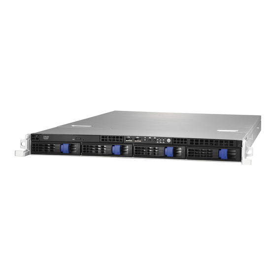
Page 24: About The Product
About the Product The following views show you the product. 1.6.1 System Front View http://www.tyan.com... -
Page 25: System Rear View
1.6.2 System Rear View B8236G24V4H-IL / B8236G24W4H-IL B8236G24W4HR-IL http://www.tyan.com... -
Page 26: Led Definitions
State Color Description Green 10Mb/100Mb/1000Mb linked RJ-45 Blinking Green 10Mb/100Mb/1000Mb activity Activity(left) No LAN linked Amber 1000Mb linked RJ-45 Green 100Mb linked Linkage(Right) 10Mb mode or No LAN linked NOTE: “Left” and “Right” are viewed from the rear panel. http://www.tyan.com... - Page 27 Color: Amber Color: Green No Driver Present or power disconnected OFF OFF Driver Present No Activity OFF ON Access Activity OFF Blinking HDD Fail On Solid OFF Identify (Locate the HDD) Blinking(1Hz) x SAS/SATA RAID Building Blinking(4Hz) x http://www.tyan.com...
-
Page 28: Motherboard (S8236-Il) Layout
1.6.4 Motherboard (S8236-IL) Layout The diagram is representative of the latest board revision available at the time of publishing. The board you receive may not look exactly like the above diagram. http://www.tyan.com... -
Page 29: Jumpers & Connectors
Power On LED (Green) LED5 Standby LED (Green) LED6 SAS Error LED (Amber) LED7 SAS Heart Beat LED (Green) LED8 BMC Heart Beat LED (Green) Jumper Legend OPEN - Jumper OFF Without jumper cover CLOSED - Jumper ON With jumper cover http://www.tyan.com... -
Page 30: System Block Diagram
1.6.6 System Block Diagram http://www.tyan.com... -
Page 31: Internal View
1.6.7 Internal View B8236G24V4H-IL / B8236G24W4H-IL HDD Cage M1235 HDD Backplane System Fans 500W Power Supply Memory Slots CPU Sockets PCI-E Riser Card Assembly http://www.tyan.com... - Page 32 B8236G24W4HR-IL HDD Cage M1235 HDD Backplane System Fans 450W Power Supply x2 Memory Slots CPU Sockets PCI-E Riser Card Assembly M7016 Power Distribution Board http://www.tyan.com...
-
Page 33: Chapter 2: Setting Up
A grounding strap or an anti-static pad Most of the electrical and mechanical connections can be disconnected with your hands. It is recommended that you do not use pliers to remove connectors as it may damage the soft metal or plastic parts of the connectors. http://www.tyan.com... -
Page 34: Precautions
Working on a system that is connected to a power supply can be extremely dangerous. Follow the guidelines below to avoid damage to GT24-B8236-IL or injury to yourself. Ground yourself properly before removing the top cover of the ... -
Page 35: Installing Motherboard Components
CPUs, memory modules and add on cards. 2.1.1 Removing the Chassis Cover Follow these instructions to remove GT24-B8236-IL chassis cover. Unscrew the rear top cover on the back side as shown in the small diagram. Slide the rear top cover out. -
Page 36: Installing The Cpu And Heatsink
Follow the steps below on installing CPUs and CPU heatsinks. Locate the CPU socket. Pull the lever slightly away from the socket and then push it to a fully open position. Push the CPU socket cover to a fully open position. http://www.tyan.com... - Page 37 Take out the protection cap. Place the CPU into the socket and make sure that the gold arrow is located in the right direction. Close the CPU socket cover and press the lever down to secure the CPU. http://www.tyan.com...
- Page 38 Position the heatsink on top of the CPU and secure it with 2 screws. Repeat the procedures mentioned earlier to install the second CPU and heatsink. http://www.tyan.com...
-
Page 39: Installing The Memory
Align the memory module with the slot. When inserted properly, the memory slot locking levers lock automatically onto the indentations at the ends of the module. Follow the recommended memory population table to install the other memory modules. http://www.tyan.com... - Page 40 http://www.tyan.com...
- Page 41 4. Dual-rank DIMMs are recommended over single-rank DIMMs 5. Un-buffered DIMM can offer slightly better performance than registerd DIMM if populating only a single DIMM per channel 6. We don't suggest other memory installation. 7. AMD 6100 series CPU doesn't support Quad-ranks U-DIMM http://www.tyan.com...
- Page 42 SR and DR 1.25v Memory MAX speed of 1333MHz in a dual channel configuration SR and DR 1.35v Memory MAX speed of 1333MHz in a dual channel configuration SR and DR 1.5v Memory MAX speed of 1600MHz in a dual channel configuration http://www.tyan.com...
- Page 43 QR 1.25v Memory MAX speed of 1066MHz in a dual channel configuration QR 1.35v Memory MAX speed of 1066MHz in a dual channel configuration QR 1.5v Memory MAX speed of 1333MHz in a dual channel configuration http://www.tyan.com...
-
Page 44: Installing Hard Drives
2.1.4 Installing Hard Drives The GT24-B8236-IL supports four 3.5” hard drives. Follow these instructions to install a hard drive. Press the locking lever latch and pull the locking lever open. Slide the HDD tray out. Remove the 6 screws. http://www.tyan.com... - Page 45 Place a hard drive into the drive tray. Use 6 HDD screws to secure the HDD. Reinsert the HDD tray into the chassis and press the locking lever to secure the tray. http://www.tyan.com...
-
Page 46: Installing The Pci-E Cards
2.1.5 Installing the PCI-E Cards The GT24-B8236-IL supports one PCI-E expansion slot. Follow these instructions to install the PCI-E card. 1. Unscrew the riser card bracket from the chassis. 2. Lift the front edge of the riser card bracket first before taking it out from the chassis. - Page 47 3. Release the screws on both sides of the riser card bracket as shown. 4. Remove the PCI-E cover shields from the chassis. 5. Insert the PCI-E card in the direction of arrows as shown. http://www.tyan.com...
- Page 48 6. Screw the PCI-E cards firmly to the riser card bracket. http://www.tyan.com...
- Page 49 7. Secure the riser card bracket to the chassis with two screws. 8. The installation of PCI-E expansion card is now complete. http://www.tyan.com...
-
Page 50: Rack Mounting
Follow these instructions to mount the TYAN GT24-B8236-IL into an industry standard 19" rack. NOTE: Before mounting the TYAN GT24-B8236-IL in a rack, ensure that all internal components have been installed and that the unit has been fully tested. Screws List... -
Page 51: Installing The Inner Rails To The Chassis
2.2.2 Installing the inner Rails to the Chassis Screw the mounting ear to each side of TYAN GT24-B8236-IL as shown using two screws of #6-32 L5.3(D) from the supplied screws kit. Draw out the inner rails from rail assembly. Install inner rails to left and right sides of chassis using 1 M4-4L(A) screw for each side. -
Page 52: Rack Mounting The Server
Secure the outer rail to the rack using 2 brackets and 4 M5-8L(B) screws for each side. Secure the mounting brackets from inside, not outside, of the rack. Mounting Bra cket 2.2.4 Rack mounting the Server Draw out the middle rail to the latch position. http://www.tyan.com... - Page 53 Secure the mounting ears of chassis to the rack with 2 M5-15L(C) screws. NOTE: To avoid injury, it is strongly recommended that two people lift the TYAN GT24-B8236-IL into the place while a third person screws it to the rack. http://www.tyan.com...
- Page 54 NOTE http://www.tyan.com...
-
Page 55: Chapter 3: Replacing Pre-Installed Components
Motherboard, M1008 LED control board, M1235 HDD Backplane, M2091/M2091-R PCI-E Riser card, System fan, ODD drive, Power supply unit etc. Disassembly Flowchart The following flowchart outlines the disassembly procedure. Rear Components Chassis cover DIMMs Mainboard CPU/Heatsink Assembly PCI Card M2091/2091-R PCI-E Riser card Mainboard Power http://www.tyan.com... - Page 56 Front Components Chassis cover DVD ROM (optional) PCBs M1008 LED M1235 M7016 Control Board HDD Backplane Power Distribution Board http://www.tyan.com...
-
Page 57: Removing The Cover
Removing the Cover Before replacing any parts you must remove the chassis cover first. Follow Chapter 2.1.1 to remove the cover of the GT24-B8236-IL. Replacing Motherboard Components Follow these instructions to replace motherboard components, including the motherboard. 3.4.1 Replacing Expansion Card The GT24-B8236-IL has two preinstalled PCI-E ×16 riser cards,... - Page 58 Unscrew the M2091 riser card. Unscrew the M2091-R riser card. Install a new riser card onto the bracket following the procedures mentioned earlier in reverse order. http://www.tyan.com...
-
Page 59: Disconnecting All Motherboard Cables
3.4.2 Disconnecting All Motherboard Cables Before replacing the motherboard or certain components, remove cables connected to the motherboard. Follow these instructions to remove all motherboard cables. Disconnect all power cables. Disconnect all other cables. http://www.tyan.com... -
Page 60: Removing The Motherboard
After removing all of the aforementioned cables, follow the instructions below to remove the motherboard from the chassis. Remove the heatsinks and processors if installed. Remove the nine screws securing the motherboard to the chassis. Carefully lift the motherboard from the chassis. http://www.tyan.com... -
Page 61: Replacing The Slim Dvd-Rom (Optional)
Follow these instructions to replace the slim DVD-ROM. Remove the power and data cable from the slim DVD-ROM adapter. Press the tab in the directions as shown to release the DVD-ROM drive. The DVD-ROM drive will be freed from the drive bay after pressing the tab. http://www.tyan.com... - Page 62 Disconnect the power and data cables from the DVD-ROM drive. Remove two screws that secure DVD-ROM drive to the bracket. Replace the DVD-ROM drive. Secure DVD-ROM to the bracket using two screws. Then replace the unit into the drive bay and connect the DVD-ROM power and data cables. http://www.tyan.com...
-
Page 63: Replacing The Led Control Board
Follow these instructions to replace the M1008 LED control board. Remove the two screws securing the LED control board unit to the chassis. Push the LED control board unit out and unplug the cables from the connectors at the back of the unit. http://www.tyan.com... - Page 64 Remove three screws securing the LED control board to the bracket. Lift the LED control board free from the chassis. After replacing the LED control board, insert the unit into the chassis following the above procedures in reverse http://www.tyan.com...
-
Page 65: M1008 Led Control Board Features
M1008 LED Control Board Connector Pin Definition J1: USB Header Definition Definition USB1- USB2- USB1+ USB2+ J3: SSI Definition Definition PW_LED+ ID_LED+ PW_LED- ID_LED- HD/LAN3 LED+ SYS_FAULT1- HD/LAN3 LED- SYS_FAULT2- PWR_SW+ LAN1_LED+ PWR_SW- LAN1_LED- RESET+ ICH_SMBDAT RESET- ICH_SMBCLK ID_SW+ INTRU# TEMP_SENSER LAN2_LED+ EXT_INT LAN2_LED- http://www.tyan.com... -
Page 66: Replacing The System Fan
Follow these instructions to replace the cooling fans in your system. Locate the cooling fans in your system. Unplug the cables connected to the mainboard and lift the fan unit up from the chassis. Follow Step A & B to unlock the fans. http://www.tyan.com... - Page 67 40x28mm Fan Step A Step B Follow Step C & D to take out the old fan and replace with a new one. 40x28mm Fan Step C Step D http://www.tyan.com...
- Page 68 Reinstall the fans into the chassis. Connect the fan cables to the backplane fan connectors. System Fan to M1235 System Fan Connect to M1235 → Fan1 Fan1 → Fan2 Fan2 → Fan3 Fan3 → Fan4 Fan4 → Fan5 Fan5 → Fan6 Fan6 http://www.tyan.com...
-
Page 69: Replacing The M1235 Hdd Backplane
Replacing the M1235 HDD Backplane Disconnect the power cables connected to the HDD Backplane. Disconnect the Mini SAS cable and the fan cables. Remove the three screws securing the bracket to the chassis base. http://www.tyan.com... - Page 70 M1235 SATA/SAS Backplane to S8236WGM3NR SATA/SAS BP Cable Connect to S8236 MB Board → Mini-SAS Cable J17 (SAS 0 ~ 3) M1235 SATA/SAS Backplane to S8236GM3NR SATA/SAS BP Cable Connect to S8236 MB Board → Mini-SAS Cable J20 (SATA 0 ~ 3) http://www.tyan.com...
-
Page 71: M1235 Hdd Backplane Features
3.8.1 M1235 HDD Backplane Features M1235 Front View FAN7 FAN1 FAN2 FAN3 FAN4 FAN5 FAN6 J41: SGPIO J15: CPLD_JTAG J7: Fan Header J39: Mini SAS Connector http://www.tyan.com... - Page 72 M1235 Rear View J10 (HDD0) LED1 LED2 J11 (HDD1) LED4 LED3 J13 (HDD2) LED6 LED5 J14 (HDD3) LED7 LED8 http://www.tyan.com...
-
Page 73: M1235 Connector Pin Definitions
3.8.2 M1235 Connector Pin Definitions Definition +12V Definition Definition +12V +12V J15 SGPIO JTAG Definition Definition 3.3V J41 SGPIO for IOH Definition Definition SM_CLK SGPIO_0 SM_DATA SGPIO_1 SGPIO_2 SGPIO_3 HD_ERR_LED J18 Slim CDROM power Definition +12V http://www.tyan.com... - Page 74 J40 PWM select for system FAN3 Definition CPU_PWM PWM_12(FAN3) CPU_PWM2 Note: Pin 1-2 chose by CPU_PWM (Default) Pin 2-3 chose by CPU_PWM2 http://www.tyan.com...
-
Page 75: Replacing The Power Supply
Replacing the Power Supply B8236G24V4H-IL / B8236G24W4H-IL Disconnect the power cables from the motherboard and the M1235. PSU to M1235 Backplane (BP) Board Connect to M1235 → 2x2P PWR P3 → B4P P4 http://www.tyan.com... - Page 76 PSU to S8236-IL MB Power Supply Unit Connect to S8236-IL (PSU) → 2x12P PWR P1 → 2x4P PWR P2 → 2x4P PWR P7 → PSMI P8 Remove nine (9) screws that secure the power supply to the chassis. http://www.tyan.com...
- Page 77 Remove the power supply bracket and then slide out the whole power supply unit. http://www.tyan.com...
- Page 78 Install a new power supply unit following the steps in reverse. http://www.tyan.com...
-
Page 79: Replacing The M7016 Power Distribution Board
Replacing the M7016 Power Distribution Board B8236G24W4HR-IL Press the latch to pull the two power supplies out. Disconnect the cables from the M7016 power distribution board. Remove six (6) screws that secure the power distribution board to the chassis. http://www.tyan.com... -
Page 80: M7016 Power Distribution Board Feature
CONN 1x4 Pin PWR CONN PWR1 1x4 Pin PWR CONN ATX 2 2x2 Pin ATX 1 PWR CONN 3.9.3 M7016 Power Distribution Board Pin Definitions ATX1 Definition Definition +12V2 +12V2 +12V3b +12V3b ATX2 Definition Definition +12V1 +12V1 +12V3a +12V3a http://www.tyan.com... - Page 81 Definition Definition 3.3V 3.3V Power Good 5VSB +12V +12V 3.3V 3.3V +12V PS_ON Reset PW2/PW3 Definition Definition +12V Definition Definition +12V +12V J4: PSMI Connector SMBUS_CLK SMBUS_DATA Definition http://www.tyan.com...
-
Page 82: Replacing The Redundant Power Supply
3.10 Replacing the Redundant Power Supply B8236G24W4HR-IL Located the power supply cage. Press the latch to pull the power supply out. http://www.tyan.com... - Page 83 After replacing a new power supply, press and hold the latch to push the power supply back into the chassis. http://www.tyan.com...
- Page 84 NOTE http://www.tyan.com...
-
Page 85: Appendix I: Cable Connection Tables
M1235 SATA/SAS Backplane (BP) Board to S8236 MB Cable M1235 Connect to S8236-IL MB → Mini-SAS Cable → Fan cable 3. Control Cable and USB Cable M1008 LED Control Board to S8236-IL MB M1008 Connect to S8236-IL MB → Control Cable J23+J32 → USB Cable http://www.tyan.com... -
Page 86: Chassis Intrusion Cable
→ M7016PDB to M1235 Backplane (BP) Board M7016 Connect to M1235 → PDB PW3 BP PW1 B4P cable → PDB PW4 BP PW2 2X2P 5. Chassis Intrusion Cable Chassis Intrusion Cable Chassis Connect to S8236-IL MB → Intrusion Cable http://www.tyan.com... -
Page 87: Appendix Ii: Fru Parts Table
Appendix II: FRU Parts Table GT24-B8236-IL FRU Parts Item Model Number Part Number Picture Quantity Description B8236G24V4H TYAN B8236G24V4H Motherboard or B8236G24W4H B8236G24W4H Motherboard Chassis Unit 432794700001 Chassis Unit;GT24-B8236 Chassis Top CCCV-0180 34078090001 GT24 Top Cover Cover Chassis Front Front Bezel for GT24 Series... - Page 88 Mini-SAS to Mini-SAS Cable, CCBL-067O 422784300005 400mm A/C Power Cord, CCBL-0317 332810000397 L=1800mm,US type A/C Power Cord, CCBL-0300 332810000281 L=1830mm,EU type NOTE: The FRU Parts List is subject to change without prior notice. Please visit our Web site for the latest update. http://www.tyan.com...
-
Page 89: Appendix Iii: Technical Support
TYAN's tech support is some of the most impressive we've seen, with great response time and exceptional organization in general.” — Anandtech.com Please feel free to contact us directly for this service at tech-support@tyan.com Help Resources: 1. - Page 90 Return Merchandise Authorization (RMA) number. The RMA number should be prominently displayed on the outside of the shipping carton and the package should be mailed prepaid. TYAN will pay to have the board shipped back to you. ® TYAN GT24-B8236-IL Service Engineer’s Manual V1.1...
Need help?
Do you have a question about the GT24-B8236-IL and is the answer not in the manual?
Questions and answers