IBM x3650 - System M2 - 7947 User Manual
User guide
Hide thumbs
Also See for x3650 - System M2 - 7947:
- Installation manual (108 pages) ,
- Product manual (18 pages) ,
- Configuration and options manual (548 pages)
Table of Contents
Advertisement
Quick Links
Advertisement
Table of Contents

Subscribe to Our Youtube Channel
Related Manuals for IBM x3650 - System M2 - 7947


Summary of Contents for IBM x3650 - System M2 - 7947
- Page 3 System x3650 M2 Type 7947 Installation and User’s Guide...
- Page 4 Note: Before using this information and the product it supports, read the information in Appendix B, “Notices,” on page 133, and the IBM Safety Information, Environmental Notices and User Guide, and the Warranty and Support Information documents on the Documentation CD.
-
Page 5: Table Of Contents
... . 11 IBM Systems Director ..... . 12 The UpdateXpress System Pack Installer ....13 Server controls, LEDs, and power . - Page 6 Hardware service and support ....132 IBM Taiwan product service ....132...
- Page 7 Appendix B. Notices ..... . 133 Trademarks......133 Important notes .
- Page 8 System x3650 M2 Type 7947: Installation and User’s Guide...
-
Page 9: Safety
Les sikkerhetsinformasjonen (Safety Information) før du installerer dette produktet. Antes de instalar este produto, leia as Informações sobre Segurança. Antes de instalar este producto, lea la información de seguridad. Läs säkerhetsinformationen innan du installerar den här produkten. © Copyright IBM Corp. 2010... - Page 10 Important: Each caution and danger statement in this document is labeled with a number. This number is used to cross reference an English-language caution or danger statement with translated versions of the caution or danger statement in the Safety Information document. For example, if a caution statement is labeled “Statement 1,”...
- Page 11 Statement 1: DANGER Electrical current from power, telephone, and communication cables is hazardous. To avoid a shock hazard: v Do not connect or disconnect any cables or perform installation, maintenance, or reconfiguration of this product during an electrical storm. v Connect all power cords to a properly wired and grounded electrical outlet.
- Page 12 Statement 2: CAUTION: When replacing the lithium battery, use only IBM Part Number 33F8354 or an equivalent type battery recommended by the manufacturer. If your system has a module containing a lithium battery, replace it only with the same module type made by the same manufacturer.
- Page 13 Statement 3: CAUTION: When laser products (such as CD-ROMs, DVD drives, fiber optic devices, or transmitters) are installed, note the following: v Do not remove the covers. Removing the covers of the laser product could result in exposure to hazardous laser radiation. There are no serviceable parts inside the device.
- Page 14 Statement 4: ≥ 18 kg (39.7 lb) ≥ 32 kg (70.5 lb) ≥ 55 kg (121.2 lb) CAUTION: Use safe practices when lifting. Statement 5: CAUTION: The power control button on the device and the power switch on the power supply do not turn off the electrical current supplied to the device.
- Page 15 Statement 8: CAUTION: Never remove the cover on a power supply or any part that has the following label attached. Hazardous voltage, current, and energy levels are present inside any component that has this label attached. There are no serviceable parts inside these components.
- Page 16 System x3650 M2 Type 7947: Installation and User’s Guide...
-
Page 17: Chapter 1. The System X3650 M2 Type 7947 Server
If you participate in the IBM client reference program, you can share information about your use of technology, best practices, and innovative solutions; build a professional network;... - Page 18 The SAS ID for each bay is printed on the server front, above each bay. If firmware and documentation updates are available, you can download them from the IBM Web site. The server might have features that are not described in the documentation that comes with the server, and the documentation might be updated...
-
Page 19: The Ibm Documentation Cd
Note: The illustrations in this document might differ slightly from your hardware. You can download an IBM ServerGuide Setup and Installation CD to help you configure the hardware, install device drivers, and install the operating system. For more information, see “Using the ServerGuide Setup and Installation CD” on page 119. -
Page 20: Related Documentation
Safety Information This document is in PDF on the IBM Documentation CD. It contains translated caution and danger statements. Each caution and danger statement that appears in the documentation has a number that you can use to locate the corresponding statement in your language in the Safety Information document. - Page 21 Environmental Notices and User Guide This document is in PDF on the IBM Documentation CD. It contains translated environmental notices. v IBM License Agreement for Machine Code This document is in PDF on the IBM Documentation CD. It provides translated versions of the IBM License Agreement for Machine Code for your product.
-
Page 22: Notices And Statements In This Document
Notices and statements in this document The caution and danger statements in this document are also in the multilingual Safety Information document, which is on the Documentation CD. Each statement is numbered for reference to the corresponding statement in your language in the Safety Information document. - Page 23 Four Ethernet ports (two on system – Shipment: 5% to 100% board and two additional ports when Drives: v Particulate contamination: the optional IBM Dual-Port 1 Gb CD/DVD (optional) : SATA interface 24x Ethernet Daughter Card is installed) Attention: Airborne particulates and...
-
Page 24: What Your Server Offers
The server uses the following features and technologies: v UEFI-compliant server firmware IBM System x Server Firmware offers several features, including Unified Extensible Firmware Interface (UEFI) 2.1 compliance, Active Energy Manager technology, enhanced RAS capabilities, and BIOS compatibility support. UEFI replaces the basic input/output system (BIOS) and defines a standard interface between the operating system, platform firmware, and external devices. - Page 25 – Event logs for ServeRAID controllers and service processors The diagnostic programs create a merged log that includes events from all collected logs. The information is collected into a file that you can send to IBM service and support. Additionally, you can view the information locally through a generated text report file.
- Page 26 IBM X-Architecture technology IBM X-Architecture technology combines proven, innovative IBM designs to make your Intel-processor-based server powerful, scalable, and reliable. For more information, see http://www.ibm.com/servers/eserver/xseries/xarchitecture/ enterprise/index.html. ™ – Active Memory ™ The Active Memory feature improves the reliability of memory through memory mirroring.
-
Page 27: Reliability, Availability, And Serviceability Features
The server contains an integrated management module (IMM) which enables you to manage the functions of the server locally and remotely. The addition of the optional IBM Virtual Media Key provides remote presence and blue-screen capture capability. The IMM also provides system monitoring, event recording, and dial-out alert capability. -
Page 28: Ibm Systems Director
A set of common tasks that are included with IBM Systems Director provides many of the core capabilities that are required for basic management, which means instant out-of-the-box business value. -
Page 29: The Updatexpress System Pack Installer
Managing the life cycles of virtual resources For more information about IBM Systems Director, see the documentation on the IBM Systems Director DVD that comes with the server and the IBM xSeries Systems Management Web page at http://www.ibm.com/systems/management/, which presents an overview of IBM Systems Management and IBM Systems Director. -
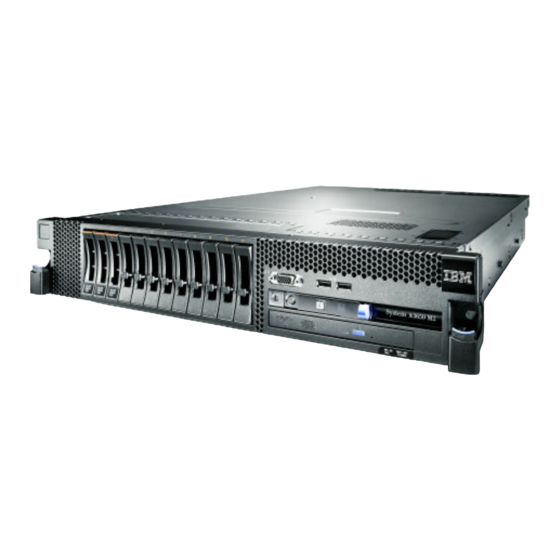
Page 30: Front View
Front view The following illustration shows the controls, connectors, and hard disk drive bays on the front of the server. Hard disk drive activity LED: Each hard disk drive has an activity LED. When this LED is flashing, it indicates that the drive is in use. Hard disk drive status LED: Each hard disk drive has a status LED. -
Page 31: Operator Information Panel
Locator button and locator LED: Use this LED to visually locate the server among other servers. Press this button to turn on or turn off this LED locally. You can use IBM Systems Director to light this LED remotely. Light path diagnostics panel The light path diagnostics panel is on the top of the operator information panel. - Page 32 The remind function is controlled by the IMM. v NMI button: Press this button to force a nonmaskable interrupt to the microprocessor, if directed to do so by IBM service and support. v Reset button: Press this button to reset the server and run the power-on self-test (POST).
-
Page 33: Rear View
Rear view The following illustration shows the connectors on the rear of the server. Ethernet connectors: Use any of these connectors to connect the server to a network. Power-cord connector: Connect the power cord to this connector. USB connectors: Connect a USB device, such as USB mouse, keyboard, or other USB device, to any of these connectors. - Page 34 This LED is the same as the system-error LED on the front of the server. Locator LED: Use this LED to visually locate the server among other servers. You can use IBM Systems Director to light this LED remotely. This LED is the same as the system-locator LED on the front of the server.
- Page 35 Power-supply LEDs The following illustration shows the power-supply LEDs on the rear of the server. For more information about solving power-supply problems, see the Problem Determination and Service Guide. The following table describes the problems that are indicated by various combinations of the power-supply LEDs and the power-on LED on the operator information panel and suggested actions to correct the detected problems.
-
Page 36: Server Power Features
Table 2. Power-supply LEDs Power-supply LEDs Error Description Action Notes No ac power to This is a normal 1. Check the ac power to the server. the server or a condition when no 2. Make sure that the power cord is problem with the ac power is present. -
Page 37: Turning Off The Server
v If a power failure occurs while the server is turned on, the server will restart automatically when power is restored. v If your operating system supports the Wake on LAN feature, the Wake on LAN feature can turn on the server. For 32-bit operating systems only: Some memory is reserved for various system resources and is unavailable to the operating system. - Page 38 System x3650 M2 Type 7947: Installation and User’s Guide...
-
Page 39: Chapter 2. Installing Optional Devices
This chapter provides detailed instructions for installing optional hardware devices in the server. Server components The following illustrations show the major components in the server. Note: The illustrations in this document might differ slightly from your hardware. © Copyright IBM Corp. 2010... -
Page 40: System-Board Internal Connectors
System-board internal connectors The following illustration shows the internal connectors on the system board. System x3650 M2 Type 7947: Installation and User’s Guide... -
Page 41: System-Board External Connectors
System-board external connectors The following illustration shows the external input/output connectors on the system board. Chapter 2. Installing optional devices... -
Page 42: System-Board Switches And Jumpers
System-board switches and jumpers Some server models come with the Pass 8 level system board or the Pass 9 level system board. The Pass 8 level system board does not have an identifying mark. The Pass 9 level system board is identified by P9 on the corner of the system board near the USB connectors on the rear of the server. - Page 43 Table 3. Pass 8 level system board jumpers Jumper number Jumper name Jumper setting UEFI boot recovery jumper v Pins 1 and 2: Normal (default) Loads the primary server (formerly BIOS) firmware ROM page. v Pins 2 and 3: Loads the secondary (backup) server firmware ROM page.
- Page 44 Table 4. Pass 8 level system board SW3 switch definition (continued) Switch number Default position Description When you toggle this switch to On and then Off, you force a power-on, which overrides the power-on and power-off button on the server and they become nonfunctional.
- Page 45 IMM recovery jumper (J147) UEFI boot recovery jumper (J29) SW3 switch block SW4 switch block The following table describes the jumper settings for J29 and J147 on the Pass 9 level system board. Table 5. System board jumpers Jumper Jumper number name Jumper setting...
- Page 46 Table 5. System board jumpers (continued) Jumper Jumper number name Jumper setting Notes: 1. If no jumper is present, the server responds as if the pins are set to 1 and 2. 2. Changing the position of the UEFI boot recovery jumper from pins 1 and 2 to pins 2 and 3 before the server is turned on alters which flash ROM page is loaded.
- Page 47 Table 6. Pass 9 level system board switch block 3, switches 1 - 4 Switch number Default value Switch description Clear CMOS memory. When this switch is toggled to On, it clears the data in CMOS memory, which clears the power-on password. Reserved.
-
Page 48: System-Board Leds
System-board LEDs The following illustration shows the light-emitting diodes (LEDs) on the system board. Note: Error LEDs remain lit only while the server is connected to power. System pulse LEDs The following LEDs are on the system board and monitor the system power-on and power-off sequencing and boot progress (see “System-board LEDs”... - Page 49 Table 8. System-pulse LEDs (continued) Description Action IMM heartbeat Indicates the status of the If the LED does not begin boot process of the IMM. flashing within 30 seconds of when the server is connected When the server is to power, complete the connected to power this LED following steps: flashes quickly to indicate...
-
Page 50: Sas Riser-Card Connectors And Leds
SAS riser-card connectors and LEDs The following illustrations show the connectors and LEDs on the SAS riser cards. Note: Error LEDs remain lit only while the server is connected to power. A 12-drive-capable model server contains the riser card that is shown in the following illustration. -
Page 51: Pci Riser-Card Adapter Connectors
PCI riser-card adapter connectors The following illustration shows the connectors on the PCI riser card for user-installable PCI adapters. PCI riser-card assembly LEDs The following illustration shows the light-emitting diodes (LEDs) on the PCI riser-card assembly. Note: Error LEDs remain lit only while the server is connected to power. Chapter 2. -
Page 52: Installation Guidelines
If the server is not working correctly, see “Solving problems” in the Installation Guide on the IBM Documentation CD for diagnostic information. v Observe good housekeeping in the area where you are working. Place removed covers and other parts in a safe place. -
Page 53: System Reliability Guidelines
When you are finished working on the server, reinstall all safety shields, guards, labels, and ground wires. v For a list of supported optional devices for the server, see http://www.ibm.com/ servers/eserver/serverproven/compat/us/. System reliability guidelines... -
Page 54: Handling Static-Sensitive Devices
v Remove jewelry, such as bracelets, necklaces, rings, and loose-fitting wrist watches. v Remove items from your shirt pocket, such as pens and pencils, that might fall into the server as you lean over it. v Avoid dropping any metallic objects, such as paper clips, hairpins, and screws, into the server. -
Page 55: Internal Cable Routing And Connectors
Internal cable routing and connectors The following illustration shows the internal routing and connectors for the two SAS signal cables (in server models with eight SAS drive bays). Notes: 1. To connect the SAS signal cables, make sure that you first connect the signal cable, and then the power cable and signal cable. - Page 56 The following illustration shows the internal routing and connector for the operator information panel cable. Top cover latch receptacle Operator panel cable The following illustration shows the internal routing and connector for the USB/video cable. Note: The USB cable is routed under the video cable and then both the USB and video cables are routed under the cable retention tab and the top cover latch receptacle.
- Page 57 The following illustration shows the internal routing for the configuration cable. The following illustrations show the internal routing for the SAS hard disk drive backplane cables. Chapter 2. Installing optional devices...
- Page 58 System x3650 M2 Type 7947: Installation and User’s Guide...
-
Page 59: Removing The Cover
Removing the cover The following illustration shows how to remove the cover. Important: Before you install optional hardware, make sure that the server is working correctly. Start the server, and make sure that the operating system starts, if an operating system is installed, or that a 19990305 error code is displayed, indicating that an operating system was not found but the server is otherwise working correctly. -
Page 60: Removing A Pci Riser-Card Assembly
Express x8 connectors. You can replace a PCI Express riser-card assembly with a riser-card assembly that contains one PCI Express Gen 2 x16 connector or that contains two PCI-X 64-bit 133 MHz connectors. See http://www.ibm.com/servers/ eserver/serverproven/compat/us/ for a list of riser-card assemblies that you can use with the server. -
Page 61: Installing A Pci Riser-Card Assembly
Installing a PCI riser-card assembly To install a PCI riser-card assembly, complete the following steps. Note: The illustrations in this document might differ slightly from your hardware. 1. Read the safety information that begins on page vii and “Installation guidelines” on page 36. -
Page 62: Removing The Microprocessor 2 Air Baffle
Removing the microprocessor 2 air baffle When you work with some optional devices, you must first remove the microprocessor 2 air baffle to access certain components. The following illustration shows how to remove the microprocessor 2 air baffle. To remove the microprocessor 2 air baffle, complete the following steps: 1. -
Page 63: Installing The Microprocessor 2 Air Baffle
Installing the microprocessor 2 air baffle To install the microprocessor 2 air baffle, complete the following steps: 1. Read the safety information that begins on page vii and “Installation guidelines” on page 36. 2. Make sure that the server and peripheral devices are turned off (see “Turning off the server”... -
Page 64: Removing The Dimm Air Baffle
Removing the DIMM air baffle When you work with some optional devices, you must first remove the DIMM air baffle to access certain components or connectors on the system board. The following illustration shows how to remove the DIMM air baffle. To remove the DIMM air baffle, complete the following steps: 1. -
Page 65: Installing The Dimm Air Baffle
Installing the DIMM air baffle The following illustration shows how to install the DIMM air baffle. To install the DIMM air baffle, complete the following steps: 1. Read the safety information that begins on page vii and “Installation guidelines” on page 36. 2. -
Page 66: Installing The Full-Length-Adapter Bracket
Installing the full-length-adapter bracket If you are installing a full-length adapter in the upper riser-card PCI slot, you must first install the full-length-adapter bracket in the end of the riser-card assembly. To install the full-length-adapter bracket, complete the following steps: 1. -
Page 67: Installing A Pci Adapter
Some high performance video adapters are supported by your server. See http://www.ibm.com/servers/eserver/serverproven/compat/us/ for more information. v The following notes describe important information about the NVIDIA video adapter that comes preinstalled in some server models: –... - Page 68 v The system scans devices in the following order, if you have not changed the default boot precedence: – Video Unified Extensible Firmware Interface (UEFI) (fixed) – System board Ethernet 1 PXE (fixed) – System board Ethernet 2 PXE (fixed) –...
- Page 69 b. Align the adapter with the adapter connector on the riser-card and the guide on the external end of the PCI riser-card assembly. c. Press the adapter firmly into the adapter connector on the riser card. 8. Connect any required cables to the adapter. Attention: v When you route cables, do not block any connectors or the ventilated space around any of the fans.
-
Page 70: Removing A Pci Adapter
v PCI riser connector 1: Carefully fit the two alignment slots on the side of the assembly onto the two alignment brackets in the side of the chassis; align the rear of the assembly with the guides on the rear of the server. v PCI riser connector 2: Carefully align the bottom edge (the contact edge) of the riser-card assembly with the PCI riser-card connector on the system board;... -
Page 71: Installing An Ibm Virtual Media Key
“Completing the installation” on page 106. Installing an IBM Virtual Media Key The optional IBM Virtual Media Key enables the IMM remote presence and blue-screen capture capability. This feature provides graphical console redirection with remote keyboard and mouse interaction, plus remote diskette and CD/DVD drive support. -
Page 72: Installing A Hard Disk Drive
The following notes describe the type of hard disk drives that the server supports and other information that you must consider when you install a drive. For a list of supported drives, see http://www.ibm.com/servers/eserver/serverproven/compat/us/. Important: Do not install a SCSI hard disk drive in this server. - Page 73 Note: You might have to reconfigure the disk arrays after you install hard disk drives. See the RAID documentation on the IBM ServeRAID Support CD for information about RAID controllers. If you have other devices to install or remove, do so now. Otherwise, go to “Completing the installation”...
-
Page 74: Removing A Hard Disk Drive
Note: You might have to reconfigure the disk arrays after you remove a hard disk drive. See the RAID documentation on the IBM ServeRAID Support CD for information about RAID controllers. If you have other devices to install or remove, do so now. Otherwise, go to “Completing the installation”... - Page 75 Note: You might have to reconfigure the disk arrays after you install hard disk drives. See the RAID documentation on the IBM ServeRAID Support CD for information about RAID controllers. Chapter 2. Installing optional devices...
-
Page 76: Removing A Simple-Swap Hard Disk Drive
Removing a simple-swap hard disk drive Attention: To maintain proper system cooling, do not operate the server for more than 10 minutes without either a drive or a filler panel installed in each bay. To remove a hard disk drive from a simple-swap bay, complete the following steps. 1. - Page 77 PCI Express SAS controller connector USB hypervisor connector SATA tape signal Tape drive power SAS controller error LED tape signal SAS riser card (tape-enabled model server) To install a SATA or USB tape drive, complete the following steps: 1. Read the safety information that begins on page vii, “Installation guidelines” on page 36, and “Handling static-sensitive devices”...
- Page 78 The following illustration shows how to connect the SATA tape drive cables. SAS riser card Tape drive power SATA tape signal SATA tape drive signal Tape drive cable power cable The following illustration shows how to connect the USB tape drive cables. SAS riser card Tape drive power Locking...
-
Page 79: Installing A Sas/Sata 4 Pac Hdd Option
Installing a SAS/SATA 4 Pac HDD option If the server is a 12-drive-capable model with eight hard disk drive bays installed, you can install an IBM System x3650 M2 Hot-swap SAS/SATA 4 Pac HDD option. See http://www.ibm.com/servers/eserver/serverproven/compat/us/ for a list of supported optional devices. - Page 80 7. Disconnect the SAS signal cables from the SAS controller, which is connected to the SAS riser card. Leave the other end of the SAS signal cables connected to the hard disk drive backplanes. 8. Remove the SAS controller assembly from the server; then, remove the SAS controller from the SAS riser card.
Need help?
Do you have a question about the x3650 - System M2 - 7947 and is the answer not in the manual?
Questions and answers