Peco RW205 Installation Instructions Manual
Hide thumbs
Also See for RW205:
- Operating manual (24 pages) ,
- Installation manual (12 pages) ,
- Owner's manual (24 pages)
Table of Contents
Advertisement
Available languages
Available languages
Quick Links
CAUTION
▲
• Use copper wire only, insulate or wire nut all unused leads.
!
• Care should be used to avoid electrostatic discharge to the thermostat.
THE PECO WAVE WIRELESS SYSTEM™
The PECO Wave Wireless System is comprised of the TW205 or TW206 wireless thermostat
paired with a RW205 receiver. Optional accessories to the system are the SW205 wireless
occupancy sensor and SW206 wireless door switch.
The TW205 thermostat is a nonprogrammable digital thermostat that may be powered by
battery, 24 VAC, or both. It features separate heating and cooling setpoints, auto changeover,
fan control functions, and wireless communication with the RW205 receiver. The RW205
receiver is wired to the HVAC equipment and controls all outputs. The optional SW205
occupancy sensor and SW206 door switch also communicate wirelessly with the RW205
receiver to signal occupancy status.
The TW206 thermostat is the programmable model. It includes all the features of the TW205
thermostat plus 7-day programming, four time periods per day, and hold/override options.
APPLICATIONS AND FEATURES
The PECO Wave Wireless System is intended for use in PTAC, PTHP, and On/Off control
applications.
• System mode selections include: Off-Heat-Cool-Auto-Setback
• Stages: 1 Heat/1 Cool, 2 Heat/1 Cool, 1 Heat/2 Cool
• 6 outputs (RW205): 1 Heat, 1 Cool, Up to 3 Fan, Outside Air Damper / Reversing Valve
• Fan control: 1-3 Speeds, Cycling (Auto) or Continuous (On)
• Permanent memory: The thermostat does not need batteries to store user-confi gured
settings in memory. Nonvolatile memory (EEPROM) saves temperature setpoints, fan, and
system settings for unlimited time. In the event of power loss, time settings are kept for at
least one year (TW206).
• Connections for Remote Temperature Probe and Setback (RW205)
RW205 REFERENCE
RW205 Front Cover
Device connection
indicator lights
Connect button
(use paperclip
tip to depress)
RW205 with Front Cover removed to
show terminals and voltage switch
Voltage selection switch
(up position is 24V,
down position is 110V)
Terminals
© COPYRIGHT 2009 PECO, INC. ALL RIGHTS RESERVED.
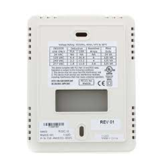
RW205 Back
2 3 4 5 6 7 8
1
RW205 WIRELESS RECEIVER
INSTALLATION INSTRUCTIONS
▲
•
READ THESE INSTRUCTIONS CAREFULLY BEFORE ATTEMPTING TO
INSTALL, OPERATE OR SERVICE THIS THERMOSTAT.
•
Failure to observe safety information and comply with instructions could result
in PERSONAL INJURY, DEATH AND/OR PROPERTY DAMAGE.
•
To avoid electrical shock or damage to equipment, disconnect power before
installing or servicing and use only wiring with insulation rated for full thermostat
operating voltage.
•
Before installing this control, the Voltage Selection Switch must be placed in the
correct position. See instructions.
•
To avoid potential fi re and/or explosion do not use in potentially fl ammable or
explosive atmospheres.
•
Retain these instructions for future reference. This product, when installed,
will be part of an engineered system whose specifi cations and performance
characteristics are not designed or controlled by PECO. You must review your
application and national and local codes to assure that your installation will be
functional and safe.
SPECIFICATIONS
Temperature Range:
Differential:
Input Power:
Wireless Type:
Wireless Range:
Operating Temperature:
Shipping Temperature:
Operating Humidity:
Physical Dimensions:
RW205 Output Ratings:
Mounting slot
VOLTAGE
24 VAC
120 VAC
Wiring passage
240 VAC
277 VAC
COMBINED LOAD CURRENT NOT TO EXCEED 20 AMPS
Mounting slot
WAVE WIRELESS SYSTEM MOUNTING CONSIDERATIONS
When selecting mounting locations for Wave Wireless System components, it is important
to consider the number and types of obstructions between components. The Wave Wireless
System will communicate through walls and other obstructions but they will reduce the
effective operating range of these devices. Mounting any device within a metal enclosure
may signifi cantly reduce its communicating range. The Wave Wireless System uses
Frequency Hopping technology to improve its resistance to wireless interference; however,
malfunctioning or improperly used wireless devices may interfere with the Wave Wireless
System. Take note of any other wireless devices in use near the Wave Wireless System
before installation or if communication errors occur frequently.
WARNING
!
50° to 90°F (10° to 32°C)
1°F (0.5°C)
TW205 / TW206 thermostat: Two AA alkaline
batteries or 24 VAC, 50/60 Hz
RW205 receiver: 24 VAC or 100-277 VAC, 50/60 Hz
902 to 928 MHz Band, FHSS
(Frequency Hopping Spread Spectrum)
100 ft minimum in open air
0° to 120°F (-17° to 48°C)
-20° to 130°F (-28° to 54°C)
5% to 95% RH, non-condensing
TW205 / TW206: 4.5"H x 5.75"W x 1.1"D
RW205: 4.8"H x 3.8"W x 1.3"D
RATINGS
RES
PILOT
AMPS
DUTY
FLA
LRA
NA
NA
NA
24 VA
5.8
34.8
6.0
125 VA
2.9
17.4
5.0
125 VA
2.4
14.4
4.2
125 VA
P/N 69566 3220-2240 REV 0 PAGE 1
HP
NA
1/4
1/4
1/4
Advertisement
Table of Contents

Subscribe to Our Youtube Channel
Related Manuals for Peco RW205


Summary of Contents for Peco RW205
- Page 1 • Stages: 1 Heat/1 Cool, 2 Heat/1 Cool, 1 Heat/2 Cool Temperature Range: 50° to 90°F (10° to 32°C) • 6 outputs (RW205): 1 Heat, 1 Cool, Up to 3 Fan, Outside Air Damper / Reversing Valve Differential: 1°F (0.5°C) •...
-
Page 2: Installation
1. Remove the RW205 Front Cover. 2. To select input power, position the voltage selection switch on the RW205 to “24V” if input power is 24 VAC, or to “110/277V” if input power is line voltage. Refer to “RW205 with Front Cover Removed”... -
Page 3: Application Notes
TW205/206, or 30 minutes for the SW205/206, the Indicator Light associated with that • Connect the HEAT OUTPUT to the COOL OUTPUT and connect both outputs to the device will shut off. In the event of a communication loss with the TW205/206, RW205 will Compressor input on the system. - Page 4 • Etapas: 1 calefacción/1 enfriamiento, 2 calefacción/1 enfriamiento, 1 calefacción/2 enfriamiento Terminales • 6 salidas (RW205): 1 calefacción, 1 enfriamiento, hasta 3 del ventilador, regulador de aire exterior/válvula de inversión • Control del ventilador: velocidades de 1a 3, cambio de ciclo (automático) o continuo (encendido) •...
-
Page 5: Instalación
RW205 en “24V” si la energía de entrada es 24 VCA o en “110/277V” si la energía de entrada es el voltaje de línea. Consulte la fi gura “RW205 sin la cubierta delantera” en Después de que el cableado y montaje del RW205 esté... -
Page 6: Notas De Aplicación
Sistemas de la bobina del ventilador El receptor RW205 no tiene un sensor de tubería, por lo tanto el cambio estacional no Sin embargo, no hay garantía de que la interferencia no ocurrirá en una instalación específi ca. se puede controlar. El sistema Wave Wireless hará funcionar los sistemas de bobina del Si este equipo no ocasiona interferencia dañina a la recepción de radio o televisión, lo cual... -
Page 7: Caractéristiques Techniques
SYSTÈME SANS FIL PAR ONDE DE PECO™ FONCTIONNER OU D’EFFECTUER L’ENTRETIEN DE CE THERMOSTAT. Le système sans fi l par onde de PECO comprend le thermostat sans fi l TW205 ou TW206 et • Le non-respect des directives de sécurité et de se conformer aux instructions peut entraîner des BLESSURES CORPORELLES, LA MORT ET/OU DES DOMMAGES... - Page 8 Le modèle de récepteur RW205 offre trois choix de montage: Climatisation • Montage dans un boîtier d’appareil de série de 2 po x 4 po. La plaque arrière du RW205 (sortie principale) est dotée d’encoches de montage pour une installation à la verticale. Voir fi gure 1 ci- dessous.
-
Page 9: Notes De Fonctionnement
• Sur le système, branchez la SORTIE CHAUFFAGE à l’entrée principale du chauffage. sans fi l. Si le RW205 indique fréquemment des messages invalides, il faut revoir la section « • Sur le système, branchez la SORTIE CLIMATISATION à l’entrée principale de la Critères de montage »... - Page 10 Pour l’installation en « Sandwich » Échelle 1:1 RW205 WIRELESS RECEIVER INSTALLATION INSTRUCTIONS PECO Automation and Controls 4707 S.E. 17th Avenue Portland, OR 97202 Phone: (503) 233-6401 Fax: (503) 233-6407 © COPYRIGHT 2009 PECO, INC. ALL RIGHTS RESERVED. P/N 69566 3220-2240 REV 0 PAGE 10...
Need help?
Do you have a question about the RW205 and is the answer not in the manual?
Questions and answers