Brother MFC6800 Service Manual
Multi-function machine
Hide thumbs
Also See for MFC6800:
- Owner's manual (222 pages) ,
- Quick setup manual (4 pages) ,
- Brochure & specs (2 pages)
Table of Contents
Advertisement
Quick Links
Advertisement
Chapters
Table of Contents
Troubleshooting

Related Manuals for Brother MFC6800


Summary of Contents for Brother MFC6800
-
Page 1: Service Manual
Multi-Function Machine SERVICE MANUAL MODEL: MFC6800/DCP1000 MFC9180/MFC9160... - Page 2 © Copyright Brother 2001 All rights reserved. No part of this publication may be reproduced in any form or by any means without permission in writing from the publisher. Specifications are subject to change without notice.
- Page 3 PREFACE This publication is a Service Manual covering the specifications, construction, theory of operation, and maintenance of the Brother multi-function machine. It includes information required for field troubleshooting and repair--disassembly, reassembly, and lubrication--so that service personnel will be able to understand machine function, to rapidly repair the machine and order any necessary spare parts.
-
Page 4: Safety Information
The label for Chinese products MANUFACTURED: JUNE 2001 BROTHER CORP. (ASIA) LTD. BROTHER BUJI NAN LING FACTORY Gold Garden Industry, Nan Ling Village, Buji, Rong Gang, Shenzhen, China. This product complies with FDA radiation performance standards, 21 CFR Subchapter J. - Page 5 CHAPTER GENERAL DESCRIPTION...
- Page 6 CHAPTER 1 GENERAL DESCRIPTION CONTENTS OUTLINE..........................1-1 1.1.1 External Appearance and Weight ................1-1 1.1.2 Components ......................1-1 SPECIFICATIONS......................1-2...
-
Page 7: Outline
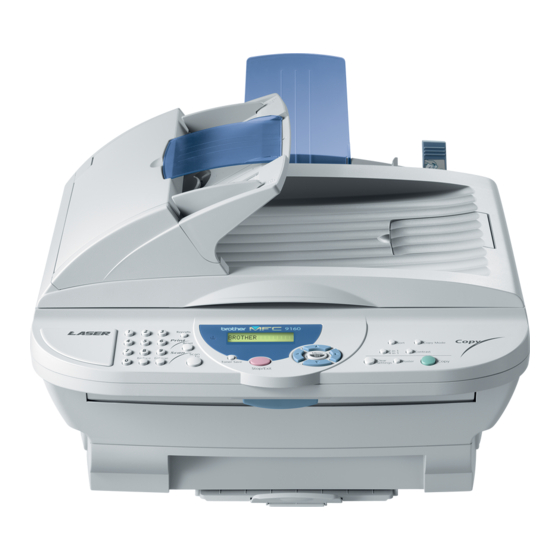
1.1 OUTLINE 1.1.1 External Appearance and Weight The figure below shows the machine appearance and approximate dimensions. (H) 354 mm 13.9" (D) 458 mm (W) 459 mm 18.0" 18.1" Weight: Machine proper Approx. 11 kg Machine (incl. drum unit & toner cartridge) Approx. -
Page 8: Specifications
500 pages (MMR/Standard Resolution) Memory Transmission (ITU-T Chart) 400 pages (MMR/Standard Resolution) Broadcasting Yes (150 locations) Manual Broadcasting Out-of-Paper Reception (Brother #1 Chart) 500 pages (MMR/Standard Resolution) Out-of-Paper Reception (ITU-T Chart) 400 pages (MMR/Standard Resolution) Auto Reduction ECM (Error Correction Mode) - Page 9 (2/2) YL4-FB(MFC) YL4-DCP Model Name MFC 6800 DCP 1000 PRINTER Color/Mono Mono Mono Engine Type Laser (YL4) Laser (YL4) Resolution (dpi) 600 x 600 600 x 600 Speed (ppm) up to 10 up to 10 Paper Capacity (sheets) Additional Paper Capacity (sheets) Output Paper Capacity (sheets) Standard Print Language Windows GDI...
- Page 10 YL4-FB(w/o Modem) Model Name MFC-9180 MFC-9160 GENERAL Print Engine Laser (YL4) Laser (YL4) Modem Speed(bps) 14,400 (Fax) Transmission Speed(sec.) Approx. 6 (brother #1chart,MMR) ITU-T Group Coding Method MH/MR/MMR Input/Output Width 5.8"-8.5"/3.5"-8.5" 5.8"-8.5"/3.5"-8.5" Input/Output Length 5"-14"/5"-14" 5"-14"/5"-14" ADF(pages) Up to 30 (75 g/m...
- Page 11 (2/2) YL4-FB(w/ Modem) YL4-FB(w/o Modem) Model Name MFC-9180 MFC-9160 PRINTER Color/Mono Mono Mono Engine Type Laser (YL4) Laser (YL4) Resolution (dpi) 600 x 600 600 x 600 Speed (ppm) up to 10 up to 10 Paper Capacity (sheets) 200 (75 g/m 200 (75 g/m Additional Paper Capacity (sheets) Output Paper Capacity (sheets)
- Page 12 CHAPTER INSTALLATION...
- Page 13 CHAPTER 2 INSTALLATION CONTENTS INSTALLING THE UPDATE DATA TO THE FACSIMILE MACHINE......2-1 SETTING ID CODES TO FACSIMILE MACHINES ............2-3...
- Page 14 2.1 INSTALLING THE UPDATE DATA TO THE FACSIMILE MACHINE If the program version is updated or the main PCB is replaced, then install the update program onto the flash ROM of the main PCB. The program installation requires a PC/AT-compatible computer (which is capable of running MS- DOS or its compatible OS).
- Page 15 Installing the update data onto the flash ROM of the facsimile machine NOTE: The following is an installation procedure example on a PC that is running Windows 95/98. (1) Copy the update data and transfer utility onto the desired directory of the hard disk. e.g., C:\UPDATE (2) Click the Start button, point to Programs, and then click MS-DOS Prompt to open an MS-DOS window.
- Page 16 MACHINES Function Brother facsimile machines are assigned unique ID codes (character strings) at the factory. If you replace the main PCB of the machine, the machine will lose its assigned ID code so that it will not be identified by the connected PC*.
-
Page 17: Theory Of Operation
CHAPTER THEORY OF OPERATION... -
Page 18: Table Of Contents
CHAPTER 3 THEORY OF OPERATION CONTENTS OVERVIEW ........................3-1 MECHANISMS .........................3-2 3.2.1 Scanner Mechanism ....................3-4 3.2.2 Laser Printing Mechanism..................3-6 3.2.2.1 Paper pulling-in, registration, feeding, and ejecting mechanism....3-6 3.2.2.2 Print process mechanism................3-8 3.2.2.3 Heat-fixing mechanism ................3-9 3.2.3 Sensors and Actuators ..................3-10 CONTROL ELECTRONICS...................3-12 3.3.1 Configuration ......................3-12... -
Page 19: Overview
3.1 OVERVIEW * Provided on models supporting facsimile function. 3 -1... -
Page 20: Mechanisms
3.2 MECHANISMS The facsimile machine is classified into the following mechanisms: n SCANNER MECHANISM - ADF mechanism - Document scanning mechanism n LASER PRINTING MECHANISM - Paper pulling-in and registration mechanism - Print process mechanism (consisting of charging, exposing, developing, transferring, and erasing processes) with paper feeding mechanism - Heat-fixing mechanism with paper feeding mechanism... - Page 21 3 -3...
- Page 22 3.2.1 Scanner Mechanism This mechanism consists of the document guide base, ADF & document tray ASSY and scanner unit. The ADF (automatic document feeder) unit contains a separation roller ASSY, document feed roller ASSY, document ejection roller, ADF motor, and document front and rear sensors. The scanner unit consists of a scanner top cover, CCD unit, CCD drive mechanism, CCD HP sensor, and scanner base.
- Page 23 This scanner mechanism supports a dual scanning system. (1) If you set documents on the document guide base with their faces up and start the scanning operation, then the ADF motor rotates to pull in those documents into the ADF unit, starting from the top sheet to the bottom, page by page.
-
Page 24: Laser Printing Mechanism
3.2.2 Laser Printing Mechanism 3.2.2.1 Paper pulling-in, registration, feeding, and ejecting mechanism 3 -6... - Page 25 Paper pulling-in and registration mechanism The paper pulling-in and registration mechanism consists of the pull-in roller gear (incorporated in the auto sheet feeder ASF), planetary gear system, paper feed solenoid, solenoid lever, clutch release lever, and registration sensor. (For the details about the sensor, refer to Subsection 3.2.3.) If the main motor rotates clockwise, the rotation is transmitted to the intermediate gear of the planetary gear system.
-
Page 26: Print Process Mechanism
3.2.2.2 Print process mechanism The print process unit works with laser beam, electrical charges, and toner. The graph below shows the transition of electrical charge on the surface of the laser-sensitive drum through the five processes: charging, exposing, developing, transferring, and erasing processes. A single cycle of laser-sensitive drum operation +1000... -
Page 27: Heat-Fixing Mechanism
3.2.2.3 Heat-fixing mechanism As the paper passes between the heater roller and the pressure roller in the heat-fixing unit, the heater roller fuses the toner on the paper. 3 -9... -
Page 28: Sensors And Actuators
3.2.3 Sensors and Actuators This machine has ten sensors: seven photosensors, two thermistors and a mechanical switch as described below. Sensor name Type Located on Document front sensor Photosensor Document sensor PCB in the Document rear sensor Photosensor Document tray open sensor Mechanical switch Document tray Scanner open sensor... - Page 29 Location of Sensors and Actuators 3 -1 1...
-
Page 30: Control Electronics
3.3 CONTROL ELECTRONICS 3.3.1 Configuration The hardware configuration of the facsimile machine is shown below. Configuration of Facsimile Machine (NOTE 1) Provided on models equipped with facsimile function. (NOTE 2) Provided on the European, Pacific, and Asian versions. 3 -1 2... - Page 31 CHAPTER DISASSEMBLY/REASSEMBLY AND LUBRICATION...
- Page 32 CHAPTER 4 DISASSEMBLY/REASSEMBLY AND LUBRICATION CONTENTS DISASSEMBLY/REASSEMBLY..................4-1 Safety Precautions ......................4-1 Tightening Torque List......................4-2 Preparation ........................4-4 How to Access the Object Component .................4-4 Disassembly Order Flow....................4-5 4.1.1 ADF Cover and Document Guide Base ...............4-6 4.1.2 ADF Components on the Upper ADF Chute ............4-7 4.1.3 ADF Components on the Lower ADF Chute ............4-12 4.1.4...
- Page 33 4.1.22 PCB Support and NCU PCB ................4-54 4.1.23 Scanner Grounding Plate ...................4-55 4.1.24 EL (Eraser Lamp) Board ..................4-56 4.1.25 Harness Routing....................4-57 4.1.26 Cleaning of High-voltage Contacts and Grounding Contacts......4-61 LUBRICATION .......................4-62 PERIODICAL REPLACEMENT PARTS ................4-64 MTBF/MTTR ........................4-65...
-
Page 34: Disassembly/Reassembly
4.1 DISASSEMBLY/REASSEMBLY n Safety Precautions To prevent the creation of secondary problems by mishandling, observe the following precautions during maintenance work. (1) Unplug the power cord from the power outlet before replacing parts or units. When having access to the power supply, be sure to unplug the power cord from the power outlet. (2) When servicing the optical system of the laser printing unit, be careful not to place screwdrivers or other reflective objects in the path of the laser beam. -
Page 35: Tightening Torque List
Tightening Torque List Location Screw type Q’ty Tightening torque N•m (kgf•cm) ADF thickness adjuster Taptite, pan B M3x6 0.39 ±0.10 (4 ±1) Upper ADF chute Taptite, cup B M3x10 0.69 ±0.10 (7 ±1) Lower ADF chute Taptite, cup B M3x10 0.69 ±0.10 (7 ±1) Grounding wire... - Page 36 Low-voltage power supply PCB Taptite, cup S M3x6 0. 69 ±0.20 (7 ±2) (Low-voltage insulator sheet) Grounding wire Screw, pan (washer) M4x8DB 0.39 ±0.20 (4 ±2) Power inlet support Taptite, cup S M3x6 0. 69 ±0.20 (7 ±2) High-voltage power supply PCB Taptite, bind B M4x12 0.98 ±0.20 (10 ±2)
-
Page 37: Preparation
n Preparation Prior to proceeding to the disassembly procedure, (1) Unplug - the modular jack of the telephone line (only for models equipped with the fax function), - the power cord, - the modular jack of the curled cord (and remove the handset), - the PC interface cable (parallel cable or USB cable) if connected (Not shown below), and - the modular jack of an external telephone set if connected (Not shown below). -
Page 38: Disassembly Order Flow
n Disassembly Order Flow 4 -5... -
Page 39: Adf Cover And Document Guide Base
4.1.1 ADF Cover and Document Guide Base (1) Open the ADF cover, press its front end to release the boss, and take it off (in the direction of arrows , and (2) Release the two latches of the document guide base and slide it up straight along the guides. NOTE: Do not turn it to the left. -
Page 40: Adf Components On The Upper Adf Chute
4.1.2 ADF Components on the Upper ADF Chute Gear cover (1) As illustrated below, insert the tip of a flat screwdriver into the slot and lift up the right edge of the gear cover (arrow ) and move the gear cover to the front (arrow 4 -7... - Page 41 Separation roller ASSY and document feed roller (2) From the rear end of each of the separation roller ASSY and document feed roller, remove the plastic retaining ring. Lift up the rear ends of them and take them out together with bushings NOTE: Take care not to drop bushings S.
- Page 42 Reassembling Note: If you have disassembled the separation roller ASSY, set the separation roller on its shaft with the boss facing towards the pin and then snap the plastic retaining ring into place, as illustrated below. Reassembling Note: When setting the separation roller ASSY, take care not to apply force to the spring plate at an angle, as illustrated on the previous page.
- Page 43 (4) Remove the screw and take the ADF thickness adjuster out of the upper ADF chute. NOTE: The ADF thickness adjuster is lubricated with grease, so take care not to smear surrounding parts with the grease when handing the ADF thickness adjuster. (5) At either end of the pressure roller shaft, press the latch to the right and take out the pressure rollers and their shaft.
- Page 44 Upper ADF chute (6) Remove the two screws from the upper ADF chute. (7) Open the document tray ( ). (8) From the underside of the document tray, release the two leftmost latches ( ) and then pull up the left end of the upper ADF chute ( ). Reassembling Note: When latching the upper ADF chute, first fit tabs (1) of the right end into the openings provided in the document tray, then press latches (2), (3), and (4) into place in this order as shown above.
-
Page 45: Adf Components On The Lower Adf Chute
4.1.3 ADF Components on the Lower ADF Chute Document front and rear sensor actuators (1) Lift up the document front sensor actuator. Fully turn the document rear sensor actuator counterclockwise, then lift it up. Document sensor PCB (2) Take the document sensor harness out of the cable hooks, then disconnect it from the document sensor PCB. - Page 46 Document guide clips (4) Press the tab of each document guide clip. Each clip will snap out of the document ejection roller shaft. Document ejection roller (5) Remove the pawled bushing from the front end of the document ejection roller shaft by pulling its pawls outwards.
- Page 47 Reassembling Note: When fitting the rear bushing of the document ejection roller into the cutout of the ADF drive unit, orient the boss as illustrated on the previous page. Document pressure bar (7) Open the ADF & document tray ASSY. (8) Pull either of the front and rear supports of the document pressure bar outwards and remove the document pressure bar.
- Page 48 Lower ADF chute, pinch rollers, and ADF motor (9) Take the document sensor harness out of cable hooks provided on the lower ADF chute. (10) Disconnect the ADF motor harness from the motor, then take its harness out of the cable guides and hooks.
- Page 49 (15) Remove the two screws from the ADF drive unit and release the ADF motor. NOTE: When using a screwdriver, take care not to scratch or damage gears on the ADF drive unit. Reassembling Note: When setting the ADF motor, hook the non-screw side of the flange on section "x"...
-
Page 50: Document Tray Open Sensor And Document Stopper
4.1.4 Document Tray Open Sensor and Document Stopper (1) Disconnect the document tray open sensor harness from the sensor. (2) Open the document tray. (3) Press the right and left latches of the document tray open sensor with the tip of a flat screwdriver as shown below and push it down. -
Page 51: Scanner Unit And Control Panel Assy (Together With Document Tray)
4.1.5 Scanner Unit and Control Panel ASSY (Together with Document Tray) (1) Pull the scanner open lever and open the scanner unit. (2) Unhook the two scanner springs. (The right-hand scanner spring is shorter than the left-hand one.) 4 -1 8... - Page 52 (3) At each of the right and left rear edges of the front cover, push up the lock of the front cover connector (in the direction of arrow ) and press the rear edge of the front cover inwards (arrow ) to release its boss from the front cover connector.
- Page 53 (5) While keeping the scanner unit open (in the direction of arrow ), disconnect the CCD flat cable (arrow ) from the relay PCB. NOTE: Handle the CCD flat cable with care. (6) Open the scanner unit further and lift up its rear edge to disengage it from the scanner mount. Then shift the scanner unit to the front right as shown below (arrow ) so that the relay PCB can be fully seen.
- Page 54 (7) Disconnect the following harnesses from the relay PCB: - Document tray open sensor harness - Document sensor harness - ADF motor harness - Panel harness (8) Release the grounding wire (coming from the ADF drive unit) by removing the screw. (9) Lift up the scanner unit together with the document tray and control panel ASSY.
- Page 55 (10) Remove the two screws from the bottom rear of the hinges. (11) Be sure to open the document tray, then release the harnesses (bound and covered with the cable sheath) from the latch and move them to the front in the opening. (12) Lift up the document tray.
- Page 56 (15) Remove the six screws from the underside of the scanner base. (16) Release the two latches of the control panel ASSY from the scanner base. (17) Slightly lift up the control panel ASSY and disconnect the panel harness from the control panel PCB.
- Page 57 n Reassembling Notes • When setting the document tray on the scanner unit, pass the bound harnesses (ADF motor harness, document sensor harness, document tray open sensor harness, and grounding wire) through the front section of the opening provided in the left rear corner of the document tray, with its bound section facing up (see the illustration given on page 4-22).
-
Page 58: Disassembly Of The Control Panel Assy
4.1.6 Disassembly of the Control Panel ASSY (1) Remove the two screws from the control panel PCB. (2) Slightly lift up the control panel PCB, then unlock the FPC key connector and disconnect the FPC key. Next, unlock the LCD cable connector and disconnect the LCD flat cable. (3) Remove the seven screws and take off the reinforcement plate and FPC key. -
Page 59: Disassembly Of The Scanner Unit
4.1.7 Disassembly of the Scanner Unit The disassembly job of the scanner unit should be done in a clean room to prevent dust or dirt from getting into the scanner unit. (1) Remove the four screws from the scanner top cover. (2) Separate the scanner top cover from the scanner base. - Page 60 (3) Release the CCD drive belt from boss "a." (4) At the left front end of the CCD drive belt, unhook the belt spring from boss "b." NOTE: Do not remove the belt spring or belt clip from the CCD drive belt. (5) As illustrated below, move the CCD unit to the right, lift up its front end and turn the CCD unit upright.
- Page 61 (6) Disconnect the CCD flat cable from the CCD PCB, then release the cable that is attached to the underside of the CCD unit with double-sided adhesive tape. NOTE: Only when the CCD unit or CCD flat cable is defective and requires replacement, release the flat cable.
- Page 62 (8) Remove the three screws and lift up the guide plate. (9) Remove the screw from the CCD HP sensor plate. 4 -2 9...
- Page 63 (10) Remove the two screws and take off the flat cable clamp. (11) To take out the panel harness, remove sponges F and R that are backed with adhesive tape. NOTE: Once removed, those sponges will become unusable and new parts will have to be put back in.
-
Page 64: Front Cover
4.1.8 Front Cover (1) Press the rear ends of the front cover inwards (in the direction of arrow ) to release bosses "a" from the front cover guides. (2) Remove the screw from each of the front cover guides. (3) While pulling the tab of each front cover guide up and to the front (in the direction of arrow ) to release the guide from boss "b,"... -
Page 65: Relay Pcb
4.1.9 Relay PCB (1) Disconnect the three relay harnesses from the relay PCB. (2) Remove the two screws. The cable clip will come off and the grounding wire will be released. (3) Lift up the relay PCB. Taptite, cup B M3x10 4 -3 2... -
Page 66: Scanner Mount
4.1.10 Scanner Mount (1) Remove the harness cover. NOTE: Once removed, the harness cover will become unusable and a new part will have to be put back in. (2) Remove the relay (ADF) harness from seven latches and then bring it to the right. (3) Remove the two screws from the scanner mount (4) Remove the scanner mount in the direction of the arrows. -
Page 67: Board Access Cover And Auto Sheet Feeder (Asf)
4.1.11 Board Access Cover and Auto Sheet Feeder (ASF) (1) Remove the two screws from the board access cover. (Those screws secure also the ASF to the main cover.) (2) Push down the top of the board access cover to release the two latches from the main cover, then pull it to the rear. - Page 68 [Disassembling the ASF] 1) Unhook the release lever spring. 2) Remove screw "a" and pull out the release lever. 3) Turn the release cam to the front and pull it out to the left. 4 -3 5...
- Page 69 4) At the right end of the ASF, remove the screw from the grounding leaf spring R. (It is not necessary to remove the leaf spring.) Next pull out the pawled bushing R. At the left end of the ASF, remove the sector gear and its spring. Unlatch the pawled bushing L to the left and then remove it from the paper pull-in roller shaft.
- Page 70 6) Turn the ASF upside down, then remove the registration sensor actuator. 4 -3 7...
- Page 71 7) There are two sets of pinch roller units. At each set, remove the leaf spring (in the order of shown below), pinch rollers, and pinch roller shaft. 8) At the right end of the paper feed roller, remove the screw and take off the grounding leaf spring R if you have not removed it in step 4) above.
- Page 72 10) Press the lock arm provided at the left inside of the ASF to the rear with a screwdriver, slide the ASF chute ASSY to the left, and take it out to the front. NOTE: To replace only the black film attached to the chute, do not remove the chute ASSY from the ASF.
-
Page 73: Heat-Fixing Unit, Fu Lamp, And Paper Ejection Sensor Actuator
4.1.12 Heat-fixing Unit, FU Lamp, and Paper Ejection Sensor Actuator (1) Remove the two screws from the heat-fixing unit. (2) Lift up the heat-fixing unit and disconnect the blue and brown heater wires (of the heater harness) from the heat-fixing unit. Then disconnect the heater thermistor harness from the EL (eraser lamp) board. - Page 74 (4) To take out the FU lamp from the heat-fixing unit, remove two screws "a." (5) Fully open the upper cover and remove it. (6) Unlatch the idle gear 16 and remove it. (7) Loosen screw "b." (8) Remove screw "c" and take out the lock plate. (9) Slightly lift up the left end of the heater roller and hold the left end of the FU lamp.
-
Page 75: Laser Unit And Toner Sensor Pcb
4.1.13 Laser Unit and Toner Sensor PCB (1) Disconnect the polygon motor flat cable, toner sensor harness, and laser diode harness from the main PCB. (2) Remove the three screws from the laser unit. (3) Lift up the laser unit. NOTE: When handling the laser unit, take care not to touch the inside of the unit, glass, or mirror. -
Page 76: Main Pcb
4.1.14 Main PCB (1) Disconnect the following harnesses and flat cable from the main PCB: • NCU harness • Low-voltage power harness • Main motor harness • Relay (ADF) harness • Relay (CCD/PANEL) harness • High-voltage power flat cable • Main-fan harness •... - Page 77 n Reassembling Notes • Be sure to route the harnesses and flat cable as illustrated in Subsection 4.1.25, "Harness routing D." Make sure that the main motor harness is routed closest to the main PCB and that the relay (CCD/SEN) harness is routed after other harnesses are connected. Make sure that harnesses having ferrite cores are taped.
- Page 78 Setting up the main PCB after replacement 4 -4 5...
-
Page 79: Bottom Plate
4.1.15 Bottom Plate (1) Turn the machine upside down. (2) Remove the nine screws (four "x" and five "y") from the bottom plate, then lift it up. "x": Taptite, cup S M3x6 "y": Taptite, bind B M4x12 4 -4 6... -
Page 80: Low-Voltage Power Supply Pcb
4.1.16 Low-voltage Power Supply PCB (1) Remove screw "a" and take off the low-voltage insulator sheet. (2) Remove screws "c" and "d" to release the grounding wire and power inlet support, respectively. (3) While pulling the right rear of the main cover (placed upside down) outwards to release the ON/OFF switch, lift up the power inlet support. - Page 81 n Reassembling Notes • Be sure to route the heater harness through U-shaped cutout "e" provided in the power supply shield. Then, route the AC power cable through the same cutout "e" on the heater harness. (Refer to Subsection 4.1.25, "Harness routing H." •...
- Page 82 For the new type of the power inlet support having an opening 1) Route the AC lead wires (blue and brown) through the opening provided in the power inlet support and pull them in the direction shown below to bring the ferrite cores closer to the opening.
-
Page 83: High-Voltage Power Supply Pcb
4.1.17 High-voltage Power Supply PCB (1) Remove the screw and take off the high-voltage insulator sheet. (2) Slightly lift up the high-voltage power supply PCB and disconnect the high-voltage power flat cable and EL (eraser lamp) harness. n Reassembling Notes •... -
Page 84: Main-Fan Pcb, Duct, And Fan
4.1.18 Main-Fan PCB, Duct, and Fan (1) Take off the duct by removing the two screws. (2) Unlatch the main-fan PCB and lift it up and out of the main cover. (3) Disconnect the fan harness from the PCB. (4) Take off the fan support by removing the screw. (5) Lift up the fan. -
Page 85: Power Supply Shield
4.1.19 Power Supply Shield (1) Remove the two screws and lift up the power supply shield. n Reassembling Notes • When reinstalling the power supply shield, route the low-voltage power harness through the opening and route the heater harness through U-shaped cutout "e" as shown above. 4 -5 0... -
Page 86: Speaker
4.1.20 Speaker (1) Pull the speaker spring inwards and pull up the speaker together with the spring. n Reassembling Notes • Put the speaker into place with its harness facing up. • Route the speaker harness through the latch together with the solenoid harness and main motor harness as shown above. -
Page 87: Gear Drive Unit
4.1.21 Gear Drive Unit (1) Make sure that the heat-fixing unit is removed. (2) Take out the heater harness from the cable guides provided on the top of the gear drive unit. (3) Remove the four screws and lift up the gear drive unit. (4) Remove the two screws and take off the main motor. - Page 88 (5) To take off the paper feed solenoid, solenoid lever, or clutch release lever, remove the two screws. n Reassembling Notes • If the friction spring in the gear drive unit slips off, fit the straight end of the spring in the support hole of the gear drive unit as illustrated above.
-
Page 89: Pcb Support And Ncu Pcb
4.1.22 PCB Support and NCU PCB (1) Remove the two screws and lift up the PCB support. (2) Remove the two screws and take off the NCU shield. (3) Remove the screw and take off the NCU PCB from the PCB support. (4) Disconnect the NCU harness. -
Page 90: Scanner Grounding Plate
4.1.23 Scanner Grounding Plate (1) Make sure that the heat-fixing unit is removed. (2) Remove the screw from the scanner grounding plate. (If the bottom plate has not been removed, remove screw "y" also (see page 4-46) that secures both the scanner grounding plate and bottom plate.) (3) Slightly lift up the scanner grounding plate. -
Page 91: El (Eraser Lamp) Board
4.1.24 EL (Eraser Lamp) Board Only when you need to replace the EL board (which is attached with double-sided adhesive tape), remove it according to the steps below. (1) Make sure that the EL harness is disconnected from the high-voltage power supply PCB. (Refer to Subsection 4.1.17.) (2) Make sure that the heat-fixing unit is removed. -
Page 92: Harness Routing
4.1.25 Harness Routing Harness routing A: ADF motor harness, document sensor harness, document tray open sensor harness, and grounding wire on the lower ADF chute Harness routing B: Relay PCB-related harnesses 4 -5 7... - Page 93 Harness routing C: Relay (ADF) harness on the scanner mount Harness routing D: Main PCB-related harnesses 4 -5 8...
- Page 94 Harness routing E: Relay harnesses on the main cover (after the ASF is removed) Harness routing F: Heater harness on the main cover (after the heat-fixing unit is removed) 4 -5 9...
- Page 95 Harness routing G: Laser diode harness, polygon motor flat cable, and toner sensor harness on the laser unit 4 -6 0...
- Page 96 Harness routing H: Harnesses viewed from the bottom of the machine (See the figures given below.) For the power inlet support having no opening For the power inlet support having an opening For the harness routing around the power inlet support, see page 4-47-2.
-
Page 97: Cleaning Of High-Voltage Contacts And Grounding Contacts
4.1.26 Cleaning of High-voltage Contacts and Grounding Contacts If any toner particles, paper dust or dirt are on the contacts, clean them out. This will ensure that power flows correctly to enable printing. Grounding contacts High-voltage contacts 4 -6 1... -
Page 98: Lubrication
4.2 LUBRICATION Apply the specified lubricants to the lubrication points as shown below. Lubricant amount Lubricant type Rice-sized pinch Half rice-sized pinch (Manufacturer) Thin coat of grease of grease of grease with a brush (3 mm dia. ball) (2 mm dia. ball) Molykote EM-D110 EMD1 (Dow Corning) - Page 99 [ 2 ] Separation roller ASSY and document feed roller PG0.5 PG0.5 [ 3 ] ADF thickness adjuster 4 -6 3...
- Page 100 [ 4 ] Document ejection roller PG0.5 PG0.5 [ 5 ] CCD rail in the scanner unit 4 -6 3 -1...
- Page 101 [ 6 ] Underside of the scanner unit 4 -6 3 -2...
-
Page 102: Periodical Replacement Parts
4.3 PERIODICAL REPLACEMENT PARTS Parts listed below require to be replaced periodically in order to assure the product quality. Even if it seems that those parts are not damaged in appearance, replace them at regular intervals specified below. The replacement procedure is given in Section 4.1 "DISASSEMBLY/REASSEMBLY." Replacement Interval For the replacement Parts Name... -
Page 103: Mtbf/Mttr
4.4 MTBF/MTTR The meantime between failures (MTBF) and meantime to repair (MTTR) of this machine are listed below. MTBF: At least 10,000 hours MTTR: Average 30 minutes per repair 4 -6 5... - Page 104 CHAPTER MAINTENANCE MODE...
- Page 105 CHAPTER 5 MAINTENANCE MODE CONTENTS ENTRY INTO THE MAINTENANCE MODE ..............5-1 LIST OF MAINTENANCE-MODE FUNCTIONS ..............5-2 DETAILED DESCRIPTION OF MAINTENANCE-MODE FUNCTIONS ......5-4 5.3.1 EEPROM Parameter Initialization ................5-4 5.3.2 Printout of Scanning Compensation Data ............5-5 5.3.2A Movement of CCD Unit to the Transport Position ..........5-1 5.3.3 ADF Performance Test ..................5-7 5.3.4...
-
Page 106: Entry Into The Maintenance Mode
5.1 ENTRY INTO THE MAINTENANCE MODE For machines w/ fax To make the machine enter the maintenance mode, press the Menu, *, 2, 8, 6, and 4 keys in this order. Within 2 seconds For machines w/o fax To make the machine enter the maintenance mode, press the Menu, 0, 2, 8, 6, and 4 keys in this order. -
Page 107: List Of Maintenance-Mode Functions
5.2 LIST OF MAINTENANCE-MODE FUNCTIONS Maintenance-mode Functions Reference Function Function Subsection Code (Page) 5.3.1 (5-4) EEPROM Parameter Initialization 5.3.2 (5-5) Printout of Scanning Compensation Data 5.3.2A (5-6-1) Movement of CCD Unit to the Transport Position 5.3.3 (5-7) ADF* Performance Test 5.3.4 (5-8) Test Pattern 1 5.3.5 (5-9) - Page 108 - - - - - - - - - - - - - - - - - - - - - - - - - - IMPORTANT - - - - - - - - - - - - - - - - - - - - - - - - - - - - - - - Basically, the maintenance-mode functions listed on the previous page should be accessed by service personnel only.
-
Page 109: Detailed Description Of Maintenance-Mode Functions
5.3 DETAILED DESCRIPTION OF MAINTENANCE-MODE FUNCTIONS 5.3.1 EEPROM Parameter Initialization Function The machine initializes the parameters, user switches, and firmware switches registered in the EEPROM, to the initial values. Entering the function code 01 initializes all of the EEPROM areas, but entering 91 does not initialize some areas, as listed below. -
Page 110: Printout Of Scanning Compensation Data
5.3.2 Printout of Scanning Compensation Data Function The machine prints out the white and black level data for scanning compensation. Operating Procedure Do not start this function merely after powering on the machine but start it after carrying out a sequence of scanning operation. - Page 111 Scanning Compensation Data List 5 -6...
-
Page 112: Movement Of Ccd Unit To The Transport Position
5.3.2A Movement of CCD Unit to the Transport Position Function This procedure moves the CCD unit to the transport position of the right end of its travel. After completing repairs and operation checks on the machine, you need to carry out this procedure immediately before packing and transporting the machine. -
Page 113: Adf Performance Test
5.3.3 ADF Performance Test Function The machine counts the documents fed by the automatic document feeder (ADF) and displays the count on the LCD for checking the ADF performance. Operating Procedure (1) Set documents. (Allowable up to the ADF capacity.) The "DOC. -
Page 114: Test Pattern 1
5.3.4 Test Pattern 1 Function This function, much like the copying function, prints out test pattern 1 to allow the service personnel to check for record data missing or print quality. Operating Procedure Press the 0 and 9 keys in this order in the initial stage of the maintenance mode. The figure below shows test pattern 1. -
Page 115: Firmware Switch Setting And Printout
5.3.5 Firmware Switch Setting and Printout [ A ] Firmware switch setting Function The machine incorporates the following firmware switch functions which may be activated with the procedures using the control panel keys and buttons. The firmware switches have been set at the factory in conformity to the communications standards and codes of each country. - Page 116 Firmware Switches (WSW01 through WSW46) Continued WSW No. Function WSW34 Function setting 12 WSW35 Function setting 13 WSW36 Function setting 14 WSW37 Function setting 15 WSW38 Function setting 16 in V. 34 mode WSW39 Transmission speed setting in V. 34 mode WSW40 Function setting 17 in V.
-
Page 117: Printout Of Firmware Switch Data
[ B ] Printout of firmware switch data Function The machine prints out the setting items and contents specified by the firmware switches. Operating Procedure (1) Press the 1 key twice in the initial stage of the maintenance mode. The "PRINTING" will appear on the LCD. (2) The machine prints out the configuration list as shown in the figure below. -
Page 118: Operational Check Of Lcd
5.3.6 Operational Check of LCD Function This function allows you to check whether the LCD on the control panel works normally. Operating Procedure (1) Press the 1 and 2 keys in this order in the initial stage of the maintenance mode. The LCD shows the screen given at right. - Page 119 For machines w/ fax For machines w/o fax Key & Button Entry Order 5 -1 3...
-
Page 120: Sensor Operational Check
5.3.8 Sensor Operational Check Function This function allows you to check whether the eight sensors--document front sensor, document rear sensor, scanner open sensor, registration sensor, paper ejection sensor, toner sensor, CCD HP sensor, and document tray open sensor--operate correctly. Operating Procedure (1) Press the 3 and 2 keys in this order in the initial stage of the maintenance mode. -
Page 121: Fine Adjustment Of Scanning Start/End Position
5.3.9 Fine Adjustment of Scanning Start/End Position Function This function allows you to adjust the scanning start/end position. Operating Procedure (1) Press the 5 and 4 keys in this order in the initial stage of the maintenance mode. The "SCAN START ADJ." and "1.ADF 2.FB" appear on the LCD in this order. (2) Press the 1 or 2 key. -
Page 122: Ccd Scanner Area Setting
5.3.10 CCD Scanner Area Setting Function The machine sets the CCD scanner area and stores it into the EEPROM. Operating Procedure (1) Press the 5 key twice in the initial stage of the maintenance mode. The "SCANNER AREA SET" will appear on the LCD. The machine checks and sets the area to be scanned. -
Page 123: Display Of The Machine's Log Information
5.3.12 Display of the Machine's Log Information Function The machine may display the its log information on the LCD. Operating Procedure (1) Press the 8 and 0 keys in this order in the initial stage of the maintenance mode. The USB serial number appears on the LCD. (2) For machines w/ fax: Press the Fax Start key. -
Page 124: Machine Error Code Indication
5.3.13 Machine Error Code Indication Function This function displays an error code of the last error on the LCD. Operating Procedure (1) Press the 8 and 2 keys in this order in the initial stage of the maintenance mode. The LCD shows the "MACHINE ERROR X X." (2) To stop this operation and return the machine to the initial stage of the maintenance mode, press the Stop key. -
Page 125: Cancellation Of The Memory Security Mode (Applicable To The European Version W/ Fax Only)
5.3.15 Cancellation of the Memory Security Mode (Applicable to the European version w/ fax only) Function This procedure can cancel the memory security mode. Use this procedure if the user forgets his/her password entered when setting the memory security mode so as not to exit from the memory security mode. - Page 126 CHAPTER ERROR INDICATION AND TROUBLESHOOTING...
- Page 127 CHAPTER 6 ERROR INDICATION AND TROUBLESHOOTING CONTENTS ERROR INDICATION.......................6-1 6.1.1 Machine Errors .....................6-1 [ 1 ] Error messages on the LCD ................6-1 [ 2 ] Error codes shown in the "MACHINE ERROR X X " message....6-5 6.1.2 Communications Errors..................6-7 TROUBLESHOOTING ....................6-17 6.2.1 Introduction......................6-17 6.2.2...
-
Page 128: Error Indication
6.1 ERROR INDICATION To help the user or the service personnel promptly locate the cause of a problem (if any), the machine incorporates the self-diagnostic functions which display error messages for machine errors and communications errors. For the communications errors, the machine also prints out the transmission verification report and the communications list. - Page 129 Messages on the LCD Probable Cause CHECK ORIGINAL Document loading error Remove original, and then (1) The document rear sensor detects no leading edge of a press STOP KEY. document within 10 seconds from the start of document loading operation. (See NOTE below.) (The document rear sensor stays OFF even after the document has been fed when the document front sensor was...
- Page 130 MACHINE ERROR XX "XX" indicates an error code. Refer to [ 2 ] on the following pages. Unplug machine, then call Brother. PAPER JAM Paper jam Open cover, then remove (1) The registration sensor detects no paper within the jammed paper.
- Page 131 Messages on the LCD Probable Cause SCANNER ERROR In the scanning compensation data list printed by the maintenance-mode function code 05, fifty percent or more of the white level data is faulty. (This message may appear only in the maintenance mode.) TONER EMPTY The toner sensor has detected that there is no toner in the cartridge or that no toner cartridge is loaded.
-
Page 132: 2 ] Error Codes Shown In The "Machine Error X X " Message
[ 2 ] Error codes shown in the "MACHINE ERROR X X " message Error Code Error factor (Hex.) ( 71 Polygon motor does not synchronize with the reference clock. ) ( 72 Cannot detect Beam Detect signal. ) ( 73 No toner cartridge loaded. - Page 133 Error Code Error factor (Hex.) ( AE The CCD HP sensor sticks to OFF, indicating that the CCD unit has not returned to the home position. ) ( AF The CCD HP sensor sticks to ON, indicating that the CCD unit has stayed in the home position.
-
Page 134: Communications Errors
6.1.2 Communications Errors If a communications error occurs, the machine emits an audible alarm (intermittent beeping) for approximately 4 seconds, displays the corresponding error message, and prints out the transmission verification report if the machine is in sending operation. 6 -7... - Page 135 Definition of Error Codes on the Communications List Calling Code 1 Code 2 Causes Wrong number called. Retrieval file error. Image data entry error. No dial tone detected before start of dialing. Busy tone detected before dialing. 2nd dial tone not detected. No loop current detected.* Busy tone detected after dialing or called.
- Page 136 Code 1 Code 2 Causes EOR and NULL received. Effective command not received. Unable to reserve a command receiver memory. Image data file error. Compatibility [checking the NSF and DIS] Code 1 Code 2 Causes Remote terminal only with V.29 capability in 2400 or 4800 bps transmission.
- Page 137 Instructions received from the remote terminal [checking the NSC, DTC, NSS, and DCS] Code 1 Code 2 Causes Illegal coding system requested. Illegal recording width requested. ECM requested although not allowed. Polled while not ready. No document to send when polled. Nation code or manufacturer code not coincident.
- Page 138 ID checking Code 1 Code 2 Causes Password plus "lower 4 digits of telephone number" not coincident. Password not coincident. Polling ID not coincident. Entered confidential mail box ID uncoincident with the mail box Relay broadcasting ID not coincident. Entered retrieval ID uncoincident with that of the mail box ID. DCN reception Code 1 Code 2...
- Page 139 Signal isolation Code 1 Code 2 Causes Unable to detect video signals and commands within 6 seconds after CFR is transmitted. Received PPS containing invalid page count or block count. (10) Video signal reception Code 1 Code 2 Causes Error correction sequence not terminated even at the final transmission speed for fallback.
- Page 140 (11) General communications-related Code 1 Code 2 Causes Unable to receive the next-page data. Unable to receive polling even during turn-around transmission due to call reservation. PC interface error. Transmission canceled by pressing the Stop key (before completion of the G3 FAX negotiation). Transmission canceled by pressing the Stop key (after completion of the G3 FAX negotiation).
- Page 141 Modem error details (Code 3) Code 3 Causes Timeout waiting for INFO0. Checksum error in INFO0. Timeout waiting for tone A or B. Timeout waiting for first phase reverse. Timeout waiting for probing cut-off tone. Timeout waiting for second phase reverse. Timeout waiting for end of probing.
- Page 142 Code 3 Causes S-sequence finished before prediction in phase 3. Timeout waiting for S-Sbar in phase 3. Timeout waiting for S-Sbar in phase 3. Timeout waiting for S in phase 3. Training after TRN failure. Problem with S-sequence in phase 4. FED turned off in S-sequence in phase 4.
- Page 143 (14) Machine error Code 1 Code 2 Causes Burn-in operation canceled by pressing the Stop key. Unrecoverable MODEM error. 6 -1 6...
-
Page 144: Troubleshooting
6.2 TROUBLESHOOTING 6.2.1 Introduction This section gives the service personnel some of the troubleshooting procedures to be followed if an error or malfunction occurs with the machine. It is impossible to anticipate all of the possible problems which may occur in future and determine the troubleshooting procedures, so this section covers some sample problems. - Page 145 Power requirements Check that: (1) The power supply specified on the rating plate located on the bottom of the machine is used. The supply voltage stays within the rating ±10%. (2) Each voltage level on AC input lines and DC lines is correct. (3) All cables and harnesses are firmly connected.
-
Page 146: Troubleshooting Procedures
6.2.4 Troubleshooting Procedures [ 1 ] Control panel related Trouble Check: Panel harness between the control panel PCB and relay (1) LCD shows nothing. Relay (CCD/PANEL) harness between the relay PCB and main PCB Control panel PCB Low-voltage power supply PCB Main PCB Panel harness between the control panel PCB and relay (2) Control panel inoperative. -
Page 147: 3 ] Communications Related
[ 3 ] Communications related Trouble Check: (1) No tone is transmitted. Main PCB NCU PCB [ 4 ] Paper/document feeding related Trouble Check: (1) Neither "COPY: PRESS COPY" Sensors by using the maintenance-mode function code nor "FAX: NO. & START" 32. -
Page 148: 5 ] Print-Image Related
[ 5 ] Print-image related If the received or sent image has any problem, first make a copy with the machine. If the copied image is normal, the problem may be due to the remote terminal; if it is abnormal, proceed to the following checks: Trouble Action to be taken... - Page 149 Trouble Action to be taken (3) Light At the scanner Check the following components: - CCD unit - Main PCB At the printer side Replace the toner cartridge with a new one and print 4 to 5 pages. If the problem persists, proceed to the next step. Remove the toner cartridge and start printing.
- Page 150 Trouble Action to be taken (5) Black and blurred vertical At the scanner stripes or band Check the following components: - CCD unit At the printer side Clean the paper path which may be contaminated with toner. Slide the wire cleaner to clean the corona wire inside the drum unit.
- Page 151 Trouble Action to be taken (9) White vertical streaks At the scanner Check the following components: - CCD unit At the printer side Clean the laser beam window on the laser unit. Replace the toner cartridge. Replace the drum unit. (10) White horizontal stripes At the printer side Replace the drum unit.
- Page 152 Trouble Action to be taken (12) Faulty image registration At the printer side (Leading edge of image starts Instruct the user not to load paper exceeding the limit in the ASF. too late on paper) Instruct the user to use the recommended types of paper. Replace the ASF.
- Page 153 Trouble Action to be taken (15) Dirt back of paper At the printer side Clean the pressure roller in the heat-fixing unit. Replace the heat- fixing unit. Replace the drum unit. Replace the high-voltage power supply PCB. (16) Poor fixing At the printer side Instruct the user to use paper of the recommended weight (less than 36 lb./m...
- Page 154 Trouble Action to be taken (20) Fading (black to white) At the printer side Replace the toner cartridge. Replace the high-voltage power supply PCB. (21) Gray background At the printer side Instruct the user to use paper of the recommended weight (less than 36 lb./m Clean the toner sensors (LED and light-receiver).
-
Page 155: Location Of High-Voltage Contacts And Grounding Contacts
Location of High-voltage Contacts and Grounding Contacts Grounding Contacts High-voltage Contacts For transfer roller Drum unit For developer For cleaner roller roller For grid For corona wire 6 -2 8... - Page 156 MFC6800/DCP1000 MFC9180/MFC9160 Appendix 1. EEPROM Customizing Codes...
- Page 157 EEPROM CUSTOMIZING CODES This function allows you to customize the EEPROM according to language, function settings, and firmware switch settings. Operating Procedure (1) For machines w/ fax To make the machine enter the maintenance mode, press the Menu, *, 2, 8, 6, and 4 keys in this order.
- Page 158 n EEPROM Customizing Codes List Model Versions DCP1000 MFC6800 U.S.A. 0001 9001 CANADA 0002 0002 TAIWAN 0001 Model Versions MFC9160 MFC9180 GERMANY 0003 0003 U.K. 0004 0004 FRANCE 0005 0005 NORWAY 0007 0007 BELGIUM 0008 0008 NETHERLANDS 0009 0009 SWITZERLAND 0010 0010 IRELAND...
- Page 159 MFC6800/DCP1000 MFC9180/MFC9160 Appendix 2. Firmware Switches (WSW)
- Page 160 WSW No. Function Reference Page WSW01 Dial pulse setting WSW02 Tone signal setting WSW03 PABX mode setting WSW04 TRANSFER facility setting WSW05 1st dial tone and busy tone detection WSW06 Pause key setting and 2nd dial tone detection WSW07 Dial tone setting 1 WSW08 Dial tone setting 2 WSW09...
- Page 161 WSW01 (Dial pulse setting) Selector Function Setting and Specifications No. 1 2 Dial pulse generation mode 10-N No. 3 4 60 ms Break time length in pulse dialing 67 ms 40 ms (for 16 PPS) 64 ms (at 106-ms intervals) No.
- Page 162 Selector 7: Switching between pulse (DP) and tone (PB) dialing, by the function switch This selector determines whether or not the dialing mode may be switched between the pulse (DP) and tone (PB) dialing by using the function switch. Selector 8: Default dialing mode, pulse (DP) or tone (PB) dialing This selector sets the default dialing mode (pulse dialing or tone dialing) which may be changed by the function switch.
- Page 163 WSW03 (PABX* mode setting) Selector Function Setting and Specifications CNG detection when sharing a modular wall socket with a 0: A 1: B telephone No. 2 3 4 0 0 0 : 50 ms 0 0 1 : 210 ms 0 1 0 : 500 ms Min.
- Page 164 Selectors 6 and 7: Dial tone detection in PABX These selectors activate or deactivate the dial tone detection function which detects a dial tone when a line is connected to the PABX. Setting both of these selectors to "1" activates the dial tone detection function so that the machine starts dialing upon detection of a dial tone when a line is connected.
- Page 165 WSW04 (TRANSFER facility setting) Selector Function Setting and Specifications Earth function in transfer facility 0: Provided Not provided Not used. No. 5 6 200 ms Earth time length for earth function 300 ms 500 ms 700 ms No. 7 8 80 ms Break time length for flash function 110 ms...
- Page 166 WSW05 (1st dial tone and busy tone detection Selector Function Setting and Specifications No. 1 2 3 0 0 0 3.5 sec. WAIT 0 0 1 7.0 sec. WAIT 0 1 0 10.5 sec. WAIT 1st dial tone detection 0 1 1 14.0 sec.
- Page 167 Selectors 5 and 6: Busy tone detection in automatic sending mode These selectors determine whether or not the machine automatically disconnects a line upon detection of a busy tone in automatic sending mode. Setting selector 6 to "0" ignores a busy tone so that the machine does not disconnect the line. Setting selectors 5 and 6 to "0"...
- Page 168 WSW06 (Pause key setting and 2nd dial tone detection) Selector Function Setting and Specifications No. 1 2 3 0 0 0 No pause 0 0 1 3.5 sec. WAIT 0 1 0 7 sec. WAIT 0 1 1 10.5 sec. WAIT Pause key setting and 2nd dial tone 1 0 0 14 sec.
- Page 169 Selectors 1 through 3: Pause key setting and 2nd dial tone detection Selectors No WAIT is inserted even if the Pause key is pressed. If you press the Pause key during dialing, the machine will insert WAIT as defined in the above table. If the Pause key is pressed repeatedly, the machine inserts the specified WAIT multiplied by the number of depressions.
- Page 170 WSW07 (Dial tone setting 1) Selector Function Setting and Specifications No. 1 2 Narrows by 10 Hz Frequency band range Initial value Widens by 10 Hz Line current detection 0: No 1: Yes No. 4 5 6 0 0 0 -21 dBm 0 0 1 -24 dBm...
- Page 171 WSW08 (Dial tone setting 2) Selector Function Setting and Specifications No. 1 2 3 0 0 0 50 ms 0 0 1 210 ms 0 1 0 500 ms 1st dial tone detection time length 0 1 1 800 ms 1 0 0 900 ms 1 0 1...
- Page 172 WSW09 (Protocol definition 1) Selector Function Setting and Specifications Frame length selection 0: 256 octets 1: 64 octets Use of non-standard commands 0: Allowed 1: Prohibited No. 3 4 : 4 times No. of retries : 3 times : 2 times : 1 time T5 timer 0: 300 sec.
- Page 173 WSW10 (Protocol definition 2) Selector Function Setting and Specifications Switching of DPS, following the 0: No 1: Yes CML ON/OFF Time length from transmission of 0: 100 ms 1: 50 ms the last dial digit to CML ON Time length from CML ON to 0: 2 sec.
- Page 174 WSW11 (Busy tone setting) Selector Function Setting and Specifications No. 1 : Narrows by 10 Hz Frequency band range : Initial value : Widens by 10 Hz Not used. 1: 400-600/400-600 ms 1: 175-440/175-440 ms ON/OFF time length ranges 1: 100-1000/17-660 ms (More than one setting allowed) 1: 110-410/320-550 ms 1: 100-660/100-660 ms...
- Page 175 WSW12 (Signal detection condition setting) Selector Function Setting and Specifications No. 1 1500 ms Min. OFF time length of calling 500 ms signal (Ci) 700 ms 900 ms No. 3 6 sec. Max. OFF time length of calling 7 sec. signal (Ci) 9 sec.
- Page 176 WSW13 (Modem setting) Selector Function Setting and Specifications No. 1 0 km Cable equalizer 1.8 km 3.6 km 5.6 km No. 3 -43 dBm Reception level -47 dBm -49 dBm -51 dBm 0: 0 dB 1: 8 dB 0: 0 dB 1: 4 dB Modem attenuator 0: 0 dB...
- Page 177 WSW14 (AUTO ANS facility setting) Selector Function Setting and Specifications No. 1 13 Hz Frequency band selection 15 Hz (Lower limit) 23 Hz 20 Hz No. 3 30 Hz Frequency band selection 55 Hz (Upper limit) 70 Hz 200 Hz No.
- Page 178 WSW15 (REDIAL facility setting) Selector Function Setting and Specifications No. 1 5 minutes Selection of redial interval 1 minute 2 minutes 3 minutes No. 3 16 times 1 times No. of redialings 2 times 3 times 15 times Redialing for no response sent from Redialing No redialing the called terminal...
- Page 179 WSW16 (Function setting 1) Selector Function Setting and Specifications Not used. CCITT superfine recommendation 0: OFF 1: ON Not used. Max. document length limitation 0: 400 cm 1: 90 cm Stop key pressed during reception 0: Not functional 1: Functional Selector 2: CCITT superfine recommendation If this selector is set to "1,"...
- Page 180 WSW17 (Function setting 2) Selector Function Setting and Specifications No. 1 No alarm Always valid Off-hook alarm Valid except when 'call reservation' is selected. Not used. Calendar clock type U.S.A. type 1: European type Not used. Non-ring reception 1: ON Not used.
- Page 181 WSW18 (Function setting 3) Selector Function Setting and Specifications Not used. No. 2 40 sec. Detection enabled time for CNG and 0 sec. (No detection) no tone 5 sec. 80 sec. Not used. Registration of station ID Permitted Prohibited No. 7 No monitoring Up to phase B at the Tone sound monitoring...
- Page 182 WSW19 (Transmission speed setting in V. 17 mode) Selector Function Setting and Specifications No. 1 No. 4 First transmission speed choice for 2,400 bps fallback 4,800 bps 7,200 bps 9,600 bps 12,000 bps Last transmission speed choice for fallback 14,400 bps V.
- Page 183 WSW20 (Overseas communications mode setting) Selector Function Setting and Specifications EP* tone prefix 0: OFF 1: ON Overseas communications mode 0: 2100 Hz 1: 1100 Hz (Reception) Overseas communications mode 0: OFF 1: Ignores DIS once. (Transmission) No. 4 5 : 100 ms Min.
- Page 184 WSW21 (TAD setting 1) Selector Function Setting and Specifications Not used. Erasure of message stored in the 0: Yes memory after the message transfer Selector 8: Erasure of message Setting this selector to "0" will erase the message recorded in the memory after the document retrieval feature transfers the message.
- Page 185 WSW23 (Communications setting) Selector Function Setting and Specifications 0: From the head of a series of zeros Starting point of training check (TCF) 1: From any arbitrary point No. 2 3 Allowable training error rate 0.5% No. 4 5 Decoding error rate for transmission of RTN Not used.
- Page 186 WSW24 (TAD setting 2) Selector Function Setting and Specifications Not used. No. 3 4 4 sec. Time length from CML ON to start of pseudo ring backtone 3 sec. transmission 2 sec. 1 sec. 0 dB 8 dB Attenuator for playback of ICM/ 0 dB 4 dB OGM to the line...
- Page 187 WSW25 (TAD setting 3) Selector Function Setting and Specifications No. 1 0 sec. Delay time for starting detection of 8 sec. voice signal 16 sec. 24 sec. No. 3 -43 dB (A) Detection level for no voice signal -46 dB (B) -49 dB (C) -51 dB (D) No.
- Page 188 WSW26 (Function setting 4) Selector Function Setting and Specifications Not used. Dialing during document reading into the temporary memory in in-memory 0: Disabled 1: Enabled message transmission No. 4 5 No. of CNG cycles to be detected 0.5 (A) (when the line is connected via the external telephone except in the external TAD mode or via the built- 1.5 (C)
- Page 189 WSW27 (Function setting 5) Selector Function Setting and Specifications Definition of programmable key 0: TEL key 1: TEL/POLLING key Ringer OFF setting 0: Yes 1: No Not used. Detection of distinctive ringing 0: Yes 1: No pattern Not used. Toner save mode 0: Yes 1: No NOTE: Selector 1 takes effect only in models/versions having a TEL key.
- Page 190 WSW28 (Function setting 6) Selector Function Setting and Specifications No. 1 2 3 0 0 0 0 dB 0 0 1 +1 dB 0 1 0 +2 dB Transmission level of DTMF high- 0 1 1 +3 dB band frequency signal 1 0 0 0 dB 1 0 1...
- Page 191 WSW29 (Function setting 7) Selector Function Setting and Specifications Not used. Impedance switching control in pulse 0: OFF 1: ON dialing Beep when the memory area for the 0: No 1: Yes activity report becomes full NOTE: Selectors 7 and 8 are applicable to the European version only. Selector 8: Beep when the memory area for the activity report becomes full If this selector is set to "1,"...
- Page 192 WSW31 (Function setting 9) Selector Function Setting and Specifications Not used. 0: 100% 1: Reduction rate specified Default reduction rate for failure of according to the current automatic reduction during recording paper size Not used. Minimum short-OFF duration in 0: 130 ms 1: 90 ms distinctive ringing Not used.
- Page 193 WSW32 (Function setting 10) Selector Function Setting and Specifications Not used. No. 5 Standard Default resolution Fine Super fine Photo No. 7 Automatic Default contrast Super light Super dark Selectors 5 and 6: Default resolution These selectors set the default resolution which applies when the machine is powered up or completes a transaction.
- Page 194 WSW34 (Function setting 12 Selector Function Setting and Specifications Not used. No. of CNG cycles to be detected No. 4 (when the line is connected via the machine in the F/T mode or via the external telephone in the external TAD mode) No.
- Page 195 WSW36 (Function setting 14) Selector Function Setting and Specifications ECP* mode 0: ON 1: OFF Recovery from inactive PC interface 0: Disabled 1: Enabled PC power-off recognition time 0: Normal 1: Long Not used. Escape from phase C 0: Yes 1: No No.
- Page 196 WSW37 (Function setting 15) Selector Function Setting and Specifications Printout of the stored image data of an unsent document onto the error 0: No report Erasure of the stored image data of an unsent document at the time of 0: No the subsequent in-memory message transmission Not used.
- Page 197 WSW38 (Function setting 16 in V. 34 mode) Selector Function Setting and Specifications No. 1 X : Automatic Setting of the equalizer : Fixed to 4 points : Fixed to 16 points Sending level of guard tone at 0: Normal - 7 db Normal phase 2 Stepping down the transmission...
- Page 198 WSW39 (Transmission speed setting in V. 34 mode) Selector Function Setting and Specifications No. 1 No. 5 2400 bps 4800 bps 7200 bps First transmission speed choice for fallback 9600 bps 12000 bps 14400 bps 16800 bps 19200 bps 21600 bps 24000 bps 26400 bps 28800 bps...
- Page 199 WSW40 (Function setting 17 in V. 34 mode) Selector Function Setting and Specifications Not used. Not masking Masking No. 3 3429 symbols/sec No. 4 3200 symbols/sec Masking of symbol rate(s) No. 5 3000 symbols/sec No. 6 2800 symbols/sec No. 7 Not used.
- Page 200 WSW41 (CCD fluorescent lamp and modem attenuator in V. 34 mode) Selector Function Setting and Specifications No. 1 2 3 0 0 0 16 hours 0 0 1 24 hours 0 1 0 12 hours ON-duration of the fluorescent lamp 0 1 1 8 hours built in the CCD unit...
- Page 201 WSW42 (Function setting 18) Selector Function Setting and Specifications Incoming mail server POP* Incoming mail server SMTP* Internet-FAX forward function JBIG* coding system Disabled Enabled Not used. POP: Post Office Protocol SMTP: Simple Mail Transfer Protocol JBIG: Joint Bi-level Image Group NOTE: Selectors 1 through 3 are applicable to those models equipped with LAN interface.
- Page 202 WSW44 (Speeding up scanning-1) Selector Function Setting and Specifications Not used. No. 6 7 8 0 0 0 : Obtained compensation data ineffective 0 0 1 : 1 min. Effective time length of the white 0 1 0 : 3 min. level compensation data obtained 0 1 1 : 5 min.
- Page 203 WSW45 (Speeding up scanning-2) Selector Function Setting and Specifications No. 1 2 3 0 0 0 : No automatic drawing-in 0 0 1 : 1 sec. Delay time from when documents 0 1 0 : 2 sec. are set until the ADF starts drawing 0 1 1 : 3 sec.
- Page 204 WSW46 (Monitor of power ON/OFF state) Selector Function Setting and Specifications No. 1 2 : Disabled : Monitor SELECT IN Monitoring the PC ON/OFF state : Monitor STROBE : Monitor both SELECT IN and STROBE Parallel port output pins kept at Enabled Disabled high level...
- Page 205 MFC6800/DCP1000 MFC9180/MFC9160 Appendix 3. Circuit Diagrams A. Main PCB B. Network Control Unit (NCU) PCB C. Control Panel PCB D. Power Supply PCBs E. Relay PCB Terms in circuit diagrams : Ceramic capacitor : Chemical capacitor...
- Page 206 A. Main PCB (1/5)
- Page 207 A. Main PCB (2/5)
- Page 208 A. Main PCB (3/5)
- Page 209 A. Main PCB (4/5)
- Page 210 A. Main PCB (5/5)
- Page 211 B. NCU PCB (U.S.A., Canada)
- Page 212 B. NCU PCB (U.K., Norway, Netherlands, Finland, Denmark, Sweden)
- Page 213 B. NCU PCB (Germany, France, Belgium, Switzerland, Ireland, Austria, Spain, Italy, South Africa)
- Page 214 NCU PCB (Asia/Oceania) 1/2...
- Page 215 NCU B53K479 ASSY NCU B53K479 ASSY ASSY ASIA W/O TEL OCEANIA W/O TEL ADRS. NAME NAME ZNR1 Not Assy ENC121D07A Not Assy 1/16W 0 Not Assy SH-124DZ Not Assy DTC123EK Not Assy 1SS120 JW15 Not Assy JW(10) JW29 Not Assy JW (5) JW31 JW (5)
- Page 216 C. Control Panel PCB...
- Page 217 Power Supply PCB (100-120V) Low-voltage power supply...
- Page 218 Power Supply PCB (200-240V) Low-voltage power supply (Europe)
- Page 219 Power Supply PCB (200-240V) Low-voltage power supply (Asia, Oceania)
- Page 220 Power Supply PCB High-voltage power supply...
- Page 221 E. Relay PCB...
- Page 222 April ’02 ‚ SM-FAX003 8C5613 Printed in Japan...
Need help?
Do you have a question about the MFC6800 and is the answer not in the manual?
Questions and answers