
Related Manuals for Honeywell NETAXS NX4L1


Summary of Contents for Honeywell NETAXS NX4L1
- Page 1 NetAXS™ NX4L1 Access Control Unit Installation Guide May 15, 2007 © 2007 Honeywell. All rights reserved. 7-901099, Revision A...
- Page 2 Ordering Information Please contact your local Honeywell representative or visit us on the web at www.honeywellaccess.com for information about ordering. Feedback Honeywell appreciates your comments about this manual. Please visit us on the web at www.honeywellaccess.com to post your comments.
-
Page 3: Table Of Contents
4.5 Supervised Input Wiring ....................17 4.6 NX4L1 Control Output Wiring..................18 4.7 Communications ......................21 RS-232 Communications ....................21 RS-485 Communications ....................22 Ethernet TCP/IP Communications ................24 NetAXS Access Control Unit NX4L1 Installation Guide, Document 7-901099, Revision A... - Page 4 7.3 Maximum Output Loading ....................49 7.4 Common Connections...................... 49 7.5 Mechanical........................49 7.6 Environment........................50 7.7 Communications and Wiring ................... 50 7.8 Reader Wiring........................51 7.9 NX4L1 Panel Wiring Diagram ..................52 8.0 Maintenance ............................9.0 Troubleshooting ..........................10.0 Technical Support ...........................
- Page 5 A.4.3 Reader Tamper Inputs....................66 A.4.4 Door Egress Inputs....................... 66 A.4.5 Door Status Inputs......................67 A.4.6 ACFAIL and Panel Tamper Inputs ................67 A.4.7 Additional Generic Outputs ..................68 NetAXS Access Control Unit NX4L1 Installation Guide, Document 7-901099, Revision A...
- Page 6 www.honeywell.com...
- Page 7 IST OF IGURES Figure 1: NX4L1 Panel Components ..................6 Figure 2: Tying the Field Wiring in the NX4L1 Cabinet ............11 Figure 3: NetAXS™ Panel Cabinet, Back View ..............12 Figure 4: NetAXS™ Panel Cabinet, Top View ............... 13 Figure 5: NetAXS™...
- Page 8 www.honeywell.com...
-
Page 9: Ist Of
Table 6 MIRO 32/0 DIP Switch and Jumper Settings .............. 28 Table 7 LED Status ........................48 Table 8 Communications and Wiring ..................50 Table 9 Reader Wiring ......................51 Table 10 Troubleshooting Problems and Solutions ..............55 NetAXS Access Control Unit NX4L1 Installation Guide, Document 7-901099, Revision A... - Page 10 www.honeywell.com...
-
Page 11: Netaxs™ Nx4L1 Installation
If any damage to the shipment is noticed, a claim must be filed with the Caution: commercial carrier responsible. Electro-static discharge (ESD) can damage CMOS integrated circuits and Caution: modules. To prevent damage always follow these procedures: NetAXS Access Control Unit NX4L1 Installation Guide, Document 7-901099, Revision A... -
Page 12: Product Liability, Mutual Indemnification
Customer harmless for any costs or damages including reasonable attorneys’ fees which the Customer may be required to pay as a result of the defective Product or the negligence of Honeywell, its agents or its employees. -
Page 13: Federal Communications Commission
This Class B digital apparatus meets all requirements of the Canadian Interference-Causing Equipment Regulations. Cet appareil numérique de la classe B respecte toutes les exigences du Réglement sur le matériel brouilleur du Canada. NetAXS Access Control Unit NX4L1 Installation Guide, Document 7-901099, Revision A... -
Page 14: Underwriters Laboratories Incorporated
The NetAXS™ panel is not intended as a Proprietary Alarm Unit - Category APOU, UL1076 standard. The NetAXS™ panel was reviewed using the following Honeywell readers: OmniAssure (TM) OT30, OmniClass (TM) OM40 and OM55, and OmniProx (TM) OP30 and OP40. -
Page 15: Introduction
RS-232, RS-485, or Ethernet network protocols. This document describes how to install and configure the NX4L1 access control unit. NetAXS Access Control Unit NX4L1 Installation Guide, Document 7-901099, Revision A... -
Page 16: Panel Components And Descriptions
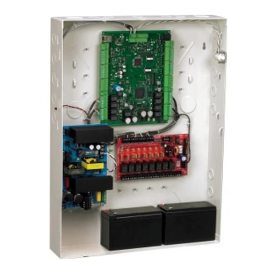
Panel Components and Descriptions 3.0 Panel Components and Descriptions The NX4L1 access control unit consists of a NetAXS panel control board, a power distribution module, a power supply, and batteries. The components are enclosed in a pre-wired cabinet. The 24V power supply provides power for the panel control board, which is a four-reader panel providing access control for up to four doors. -
Page 17: Netaxs™ Access Control Unit
Reader 2 + Reader 3 + Reader 4 + AUX Power < 600 mA. AUX Power must not be used to power locks. Caution: For NetAXS™ maximum current draw refer to panel specifications. NetAXS Access Control Unit NX4L1 Installation Guide, Document 7-901099, Revision A... -
Page 18: Power Supply
Panel Components and Descriptions 3.2 Power Supply The NX4L1 uses an internal 115 VAC to 24 VDC regulated power supply (Altronix Model AL600ULXB). The supply uses 115 VAC, 60 Hz, 2 Amp input, and provides 24 VDC at 6 Amps for the system power. The supply also charges and monitors the condition of the batteries. -
Page 19: Installation
Terminal Block (TB) 8. After the power-up sequence, check the LEDs to be sure the panel has powered up properly (see “LED Operation“ on page 47). 10.Configure the panel by following the instructions in the NetAXS™ Access Control Unit User’s Guide. NetAXS Access Control Unit NX4L1 Installation Guide, Document 7-901099, Revision A... -
Page 20: Installing The Optional Ac Inlet
6. Plug the other end of the cable into a standard non-switched 115 VAC outlet. Use only a Yung Li YC-12 power cord (HAS part number 700-0109). UL has Note: evaluated the use of this power cord with the optional AC inlet for the NX4L1. You can purchase this power cord from Honeywell. www.honeywell.com... -
Page 21: Tying The Field Wiring In The Nx4L1 Cabinet
Installation 4.2 Tying the Field Wiring in the NX4L1 Cabinet Use the following figure as a guide to secure the field wiring in the NX4L1 cabinet. Figure 2: Tying the Field Wiring in the NX4L1 Cabinet Location of wire tie points... -
Page 22: Cabinet Mounting
NetAXS™ NX4L1 Installation Installation 4.3 Cabinet Mounting The following five figures show the back, top, bottom, right, and left views of the NetAXS™ panel cabinet. Each view includes the dimensions and knockout placement that you will need to mount the cabinet. -
Page 23: Figure 4: Netaxs™ Panel Cabinet, Top View
Installation Figure 4: NetAXS™ Panel Cabinet, Top View 1 5/8" (41 mm) 31/32" (25 mm) Figure 5: NetAXS™ Panel Cabinet, Bottom View 31/32" (25 mm) 1 5/8" (41 mm) NetAXS Access Control Unit NX4L1 Installation Guide, Document 7-901099, Revision A... -
Page 24: Figure 6: Netaxs™ Panel Cabinet, Left View
NetAXS™ NX4L1 Installation Installation Figure 6: NetAXS™ Panel Cabinet, Left View 2 9/16" (65 mm) 4 23/32" (120 mm) 6 11/16" (170 mm) 8 21/32" (220 mm) 10 10/16" (270 mm) 16 30/32" (430 mm) 18 29/32" (480 mm) 22 3/8" (568.5 mm) -
Page 25: Figure 7: Netaxs™ Panel Cabinet, Right View
15 3/4" (400 mm) 17 3/16" (436.87" mm) 17 23/32" (450 mm) 13/16" (21 mm) 20 1/8" (511.5 mm) 20 11/32" (517 mm) 20 15/16" (532 mm) 22 3/8" (568mm) NetAXS Access Control Unit NX4L1 Installation Guide, Document 7-901099, Revision A... -
Page 26: Reader Wiring
NetAXS™ NX4L1 Installation Installation Table 1 lists the dimensions of the cabinet’s conduit entries. Table 1 Cabinet Electrical Entries ENCLOSURE CONDUIT CONDUIT CONDUIT 1” CONDUIT 2” 1/2” (12.7 mm) 3/4” (19.0 mm) (25.4 mm) (50.8 mm) Bottom Right Side Left Side Back 4.4 Reader Wiring... -
Page 27: Supervised Input Wiring
Door 3 REX (Egress) TB13-3 Door 3 Status TB13-4 Door 4 REX (Egress) TB13-6 Door 4 Status TB 5-6, 6-6, 11-6, Optional supervised input if not used 12-6 for a reader tamper NetAXS Access Control Unit NX4L1 Installation Guide, Document 7-901099, Revision A... -
Page 28: Nx4L1 Control Output Wiring
Refer to the NetAXS Access Control Unit User’s Guide for details on controlling the relay operations. The NX4L1 is wired to enable the internal nominal 24 VDC power supply to be used to power the access control door strikes/locks or other auxiliary loads. - Page 29 Table 4: NetAXS Relay and Power Distribution Board DIP Switch Associations Default NetAXS Board Power Distribution Power Distribution Function Relay Output Board Relay Output Board DIP Switch Door 1 Door 2 Door 3 Door 4 Auxiliary Auxiliary Auxiliary Auxiliary NetAXS Access Control Unit NX4L1 Installation Guide, Document 7-901099, Revision A...
-
Page 30: Figure 9: Power Distribution Board Field Wiring
NetAXS™ NX4L1 Installation Installation The Power Distribution Output board has two dry contact outputs that can be used to monitor the general condition of the system. The TRBL relay output is de-energized if the +24 VDC is off or if a PTC is active. -
Page 31: Communications
RS-232, DB9 (9 pin) connector to the panel’s RJ-45 serial port. Replacement cables can be obtained by contacting your Honeywell Access System Representative. Figure 10: RJ-45 Serial Port NetAXS Access Control Unit NX4L1 Installation Guide, Document 7-901099, Revision A... -
Page 32: Rs-485 Communications
NetAXS™ NX4L1 Installation Installation Figure 11: RS-232 Configuration Reader 1 NetAXS COM1 Panel Reader 4 CBL50 Terminal Reader 1 NetAXS COM2 Panel Reader 4 One NetAXS panel per COM port. Two COM ports possible. RS-485 Communications The NetAXS™ panel can reside on an existing RS-485 drop line hosted by either a NetAXS™... -
Page 33: Figure 12: Rs-485 Configuration Via N-485-Pci-2 Or Pci-3
Reader 1 Reader 1 NetAXS NS2+ NetAXS Reader 2 Reader 4 Reader 4 A combination of NetAXS and NS2+ panels, supporting a total of 31 panels per multi-drop line NetAXS Access Control Unit NX4L1 Installation Guide, Document 7-901099, Revision A... -
Page 34: Ethernet Tcp/Ip Communications
NetAXS™ NX4L1 Installation Installation Ethernet TCP/IP Communications Figure 14: Ethernet TCP/IP Configuration Network Interface Ethernet Card Inside PC Up to 255 TCP/IP Connections per System Ethernet Terminal 10/100 Reader 1 NetAXS Gateway Reader 4 RS-485 Multidrop Line Reader 1 Reader 1... -
Page 35: Figure 15: Ethernet Mac Address Location
NetAXS™ NX4L1 Installation Installation Figure 15 shows the location of the panel’s unique MAC ID. Figure 15: Ethernet MAC Address Location Label with Ethernet MAC Address NetAXS Access Control Unit NX4L1 Installation Guide, Document 7-901099, Revision A... -
Page 36: Dip Switch Settings
NetAXS™ NX4L1 Installation Installation 4.8 DIP Switch Settings Figure 16 locates the NX4L1 DIP switch panel and the J36 and J37 jumpers. Figure 16: DIP Switch and Jumper Location Switches www.honeywell.com... -
Page 37: Table 5 Dip Switch Settings
Address 23 Address 24 Address 25 Address 26 Address 27 Address 28 Address 29 Address 30 Address 31 NetAXS™ Multidrop NetAXS™ Gateway Address 0 is not a valid setting. Note: NetAXS Access Control Unit NX4L1 Installation Guide, Document 7-901099, Revision A... -
Page 38: Jumper Settings
Installation 4.9 Jumper Settings The NX4L1 panel control board includes jumpers 36 and 37, which set end-of-line termination and biasing for the Multidrop RS-485 Line. The board ships with all jumpers set to OFF. For a Multidrop RS-485 Line, you must set both J36 and J37 to CLOSED (terminated and biased) at the two end-point panels. - Page 39 3 through 6, the NetAXS™ panel will not communicate with it. The NetAXS™ board and the NX4L1 is not intended to provide either module power or module output load power for downstream I/O. A separate 24 VDC supply should be used to provide power to all downstream modules and output loads.
-
Page 40: Figure 17: Default Downstream I/O Configuration With Wiring
NetAXS™ NX4L1 Installation Installation The following figure shows the default downstream I/O system configuration with communication and power wiring. Figure 17: Default Downstream I/O Configuration with Wiring www.honeywell.com... -
Page 41: System Configuration
DIP Switch Settings S1-S5 Panel Address S6: OFF J36 OPEN J37 OPEN NetAXS It is recommended to Ear Panel NetAXS enclosure n y ar roun one side of cable NetAXS Access Control Unit NX4L1 Installation Guide, Document 7-901099, Revision A... -
Page 42: Rs-485 Connection Via Netaxs
NetAXS™ NX4L1 Installation System Configuration 5.2 RS-485 Connection via NetAXS™ This connection supports thirty-one NetAXS™ Access Controller panels for each drop line. It has been reviewed by UL. However, because UL has reviewed the NetAXS panel only as a standalone system, the computer terminal and NetAXS gateway panel appear in this illustraton only to show the installation and programming of the NetAXS panel. -
Page 43: Rs-485 Connections With Multidrop Panels At Both Ends Of The Cable
NetAXS Panel Only Earth Ground (EG) Only Earth Ground (EG) one side of cable one side of cable It is recommended to Earth Ground (EG) each NetAXS enclosure individual NetAXS Access Control Unit NX4L1 Installation Guide, Document 7-901099, Revision A... -
Page 44: Figure 21: Rs-485 Connection Via Pci-2 With Multidrop Panels At Both Ends
NetAXS™ NX4L1 Installation System Configuration Figure 21: RS-485 Connection via PCI-2 with Multidrop Panels at Both Ends RS-232 (50 Ft. Max.) COM Port RS-485 (4,000 Ft.) Terminal DIP Switch Settings S1-S5 Panel Address S6: OFF J36 OPEN J37 OPEN NetAXS... -
Page 45: Rs-232 Connection
(DB9) Request To Send (RTS) Signal Ground (GND) Receive Data (RXD) Transmit Data (TXD) Clear To Send (CTS) 9-Pin COM 1 or COM 2 to RJ-45 on NetAXS Panel NetAXS Access Control Unit NX4L1 Installation Guide, Document 7-901099, Revision A... -
Page 46: Ethernet Connection
NetAXS™ NX4L1 Installation System Configuration 5.5 Ethernet Connection This connection supports a maximum of 255 IP connections per server. It has not been reviewed by UL. Figure 23: Ethernet Connection 100BaseT (CAT 5) 328 Ft. Max. Terminal RS-485 Multidrop DIP Switch Settings... -
Page 47: Lansrlu1 Connection
120 ohm, 23 pf (HAS part no. NCP2441-TN) LANSRLU1 RJ-45 RS-232 (50 Ft.) See RS-485 Cable note each NetAXS enclosure individually Only Earth Ground (EG) one side of cable NetAXS Access Control Unit NX4L1 Installation Guide, Document 7-901099, Revision A... -
Page 48: Rs-485 Short Haul Modem Connection Via Pci-2
NetAXS™ NX4L1 Installation System Configuration 5.7 RS-485 Short Haul Modem Connection via PCI-2 This connection supports thirty-one NetAXS™ Access Controller panels for each drop line. It has not been reviewed by UL. Figure 25: RS-485 Short Haul Modem Connection via PCI-2... -
Page 49: Rs-485 Short Haul Modem Connection Via Netaxs
Male 9 Pin Male 25 Pin 2 TX 2 (TX) 2 (RX) Panel J36: CLOSED 3 RX 3 (RX) or 3 (TX) J37: CLOSED 5 Comm 7 (GND) 7 (GND) NetAXS Access Control Unit NX4L1 Installation Guide, Document 7-901099, Revision A... -
Page 50: Rs-232 Short Haul Modem Connection
NetAXS™ NX4L1 Installation System Configuration 5.9 RS-232 Short Haul Modem Connection One NetAXS™ Access Controller panel for each loop. It has not been reviewed by UL. Figure 27: RS-232 Short Haul Modem Connection RS232 Cable MODEM (DB-9) (Straight) (Null) RS-232, 50 Ft. Max. -
Page 51: M-56K Dial-Up Modem, Rs-485 Connection Via Hub
Female Male TB7-1 (RS485+) TB7-2 (RS485-) TB7-3 (RS485 COM) 4,000 ft. (1,200 m) max, 24 AWG, 2 twisted pairs with shield, 120 ohm, 23 pf (HAS part no. NCP2441-TN) NetAXS Access Control Unit NX4L1 Installation Guide, Document 7-901099, Revision A... -
Page 52: M-56K Dial-Up Modem, Rs-485 Connection Via Netaxs
NetAXS™ NX4L1 Installation System Configuration 5.11 M-56K Dial-up Modem, RS-485 Connection via NetAXS™ Thirty-one NetAXS™ Access Controller panels for each drop line. It has not been reviewed by UL. Figure 29: M-56K Dial-up Modem, RS-485 Connection via NetAXS™ M-56K FAX/MODEM... -
Page 53: Fiber Converter To Rs-485 Connection Via Pci-2
S1-S5 Panel Address 4,000 ft. (1,200 m) max, 24 AWG, 2 twisted pairs with S6: OFF shield, 120 ohm, 23 pf (HAS part no. NCP2441-TN) J36: OPEN J37: OPEN NetAXS Access Control Unit NX4L1 Installation Guide, Document 7-901099, Revision A... -
Page 54: Fiber Converter To Rs-485 Connection Via Netaxs
NetAXS™ NX4L1 Installation System Configuration 5.13 Fiber Converter to RS-485 Connection via NetAXS™ This connection supports thirty-one NetAXS™ Access Controller panels for each drop line. It has not been reviewed by UL. Figure 31: Fiber Converter to RS-485 Connection via NetAXS™... -
Page 55: N-485-Pci-2/Netaxs™ Access Controller Panel Connection Detail
J37: OPEN Ground only one side of cable shield Shield Common 485 + 485 - 4,000 ft.(1,200 m) max,24 AWG,2 twisted pairs with shield,120 ohm,23 pf (HAS part no.NCP2441-TN) NetAXS Access Control Unit NX4L1 Installation Guide, Document 7-901099, Revision A... -
Page 56: Netaxs™/Netaxs™ Access Controller Panel Connection Detail
NetAXS™ NX4L1 Installation System Configuration 5.15 NetAXS™/NetAXS™ Access Controller Panel Connection Detail Figure 33: NetAXS™/NetAXS™ Access Controller Panel Connection Detail Ground Shield DO NOT CONNECT or GROUND SHIELD To Serial Connection NetAXS TB7 NetAXS TB7 DIP Switch Settings DIP Switch Settings... -
Page 57: Netaxs™ Startup
Figure 34: System, Relay and Power LEDs RDR 3 Host RS232 and Ethernet Status RDR 4 Downstream LEDs LEDs Run LED RS485 LED RDR 1 RDR 2 Relay Status LEDs Relay Status LEDs Power NetAXS Access Control Unit NX4L1 Installation Guide, Document 7-901099, Revision A... -
Page 58: Table 7 Led Status
NetAXS™ NX4L1 Installation NetAXS™ Startup The following table indicates the status associated with each LED. Table 7 LED Status H485 H232 LINK GREEN Power Multi- RS232 Down- 100Mbit Link Relay Flash at Heart drop Receive stream Active read Beat Receive... -
Page 59: Hardware Specifications
• Enclosure Weight: – With two batteries (including the door): 33.70 lbs – With one battery (including the door): 28.90 lbs – Without batteries (including the door): 24.25 lbs NetAXS Access Control Unit NX4L1 Installation Guide, Document 7-901099, Revision A... -
Page 60: Environment
NetAXS™ NX4L1 Installation Hardware Specifications 7.6 Environment • Temperature: 0C to 49C operating, -55C to +85C storage. • Humidity: 5% to 85% RHNC. 7.7 Communications and Wiring Table 8 Communications and Wiring Maximum Maximum Distance: Communication Type Description Panels Feet (Meters) -
Page 61: Reader Wiring
Cable Specifications Description Maximum Distance: Feet (Meters) Readers NC1861-BL 6 Conductor, Shielded 500 (153) Alarm Input NC1821-GR Twisted Pair, Shielded 2,000 (610) Relay Outputs NC1821-GR Twisted Pair, Shielded 2,000 (610) NetAXS Access Control Unit NX4L1 Installation Guide, Document 7-901099, Revision A... -
Page 62: Nx4L1 Panel Wiring Diagram
NetAXS™ NX4L1 Installation Hardware Specifications 7.9 NX4L1 Panel Wiring Diagram Figure 35: NetAXS Panel Wiring Diagram Enclosure Tamper Switch RS-232 * RS-232 Ethernet * Ethernet Expansion RS485-/B TB10 Host RS485+ Expansion RS-485* Expansion RS485+/A * Host RS-485 Host RS485- Buzzer/OUT 17... -
Page 63: Maintenance
4.Replace the fuse with a new 3.5 A, 250 V fuse. 5.Re-attach the translucent fuse cover. 6.Re-attach the protective Power Supply cover with the four mounting screws. 7.Re-connect the AC power. NetAXS Access Control Unit NX4L1 Installation Guide, Document 7-901099, Revision A... - Page 64 NetAXS™ NX4L1 Installation Maintenance • Use the following procedure to change the 3, 250 V, Bussman type GMA fuse in the power inlet terminal block. Be sure to disconnect the AC power before removing the fuse holder Warning: from the power inlet terminal block.
-
Page 65: Troubleshooting
Tesla flow control off: _U=<pn>_D (disable flow control) This prevents the panels from inadvertently filling their buffers. To turn the Tesla flow control back on: _U=<pn>_E (enable flow control) NetAXS Access Control Unit NX4L1 Installation Guide, Document 7-901099, Revision A... -
Page 66: Technical Support
NetAXS™ NX4L1 Installation Technical Support The NetAXS™ EOL network is AC-coupled. There is no resistance difference Note: between the RS-485 positive and negative terminals if the EOL network is on or off (J36 and J37). 10.0 Technical Support 10.1 Normal Support Hours Monday through Friday, 7:00 a.m. -
Page 67: Netaxs™ Standalone Operation
10 seconds. 3. If the door status goes from close to open to close again during the 10 second door open period, the door relay will be immediately de-energized. NetAXS Access Control Unit NX4L1 Installation Guide, 7-901099, Revision A... -
Page 68: Standalone Settings
• Echo typed characters locally: YES • Line Delay: 500 milliseconds A.2.4 Verifying Communications 1. Press the spacebar. 2. Press the carriage return <CR>. “S?” appear for every online panel and indicates proper communication between the terminal and panel. www.honeywell.com... -
Page 69: Standalone Commands
Example #1: _T=1_08:30<CR> This command would set panel 1 to a time of 8:30 AM. Example #2 _T=6_18:15<CR> This command would set panel 6 to a time of 6:15 PM. NetAXS Access Control Unit NX4L1 Installation Guide, 7-901099, Revision A... -
Page 70: D (Date) Command
This command would set panel 1 to a date of 1/9/2007 and to Tuesday as the day of the week. Example #2: _D=25_12/14/2009_7<CR> This command would set panel 25 to a date of 12/14/2009 with a day of week being Monday. www.honeywell.com... -
Page 71: L (Time Zone) Command
This command would configure panel 25 to add a time zone entry to time zone number 45 ranging from 4PM to 11:59PM and would be valid during Saturday, Sunday, Holiday, 1, 2, and 3. NetAXS Access Control Unit NX4L1 Installation Guide, 7-901099, Revision A... -
Page 72: C (Card Add) Command
Variables: pn = panel number (1-31) code = card number (range depends on card format) Example #1: _C=6_12345<CR> This command would remove card 12345 from panel 6. Example #2 _C=18_52989<CR> This command would remove card 52989 from panel 18. www.honeywell.com... -
Page 73: W (Input) Command
E: Energize F: Follow N: No action P: Pulse Example: _P=1_I_5_O_3_E_D When Input 5 is triggered, Output 3 energizes. When Input 5 returns to its normal state, Output 3 de-energizes. NetAXS Access Control Unit NX4L1 Installation Guide, 7-901099, Revision A... -
Page 74: Flow Control Disable/Enable Command
(Use this command only for a dropline panel using RS-232 in standalone mode) _U=[panel name]_{D|E} Parameters: D: Disable E: Enable Example: _U=30_D This disables the flow control on panel 30 and prevents the panel’s buffers from filling. After a hard re-set of the panel, the flow control is re-enabled. www.honeywell.com... -
Page 75: Netaxs™ Panel Defaults
The following are the default reader LED port to output associations: Reader LED Controls... Reader 1 Output 11 Reader 2 Output 12 Reader 3 Output 13 Reader 4 Output 14 NetAXS Access Control Unit NX4L1 Installation Guide, 7-901099, Revision A... -
Page 76: Reader Tamper Inputs
Normally Closed contact. When the egress input is active, the associated output relay will be active. The following are the default egress input associations: Egress input Controls relay... Panel input Reports as... Input 1 Input 3 Input 5 Input 7 www.honeywell.com... -
Page 77: Door Status Inputs
An inactive External Power Fail input indicates that the system is operating from the primary input power. Generic input Panel input Reports as... Generic/External Power Fail Input 13 Generic/Enclosure Tamper SP10 Inputs 14 and 20 NetAXS Access Control Unit NX4L1 Installation Guide, 7-901099, Revision A... -
Page 78: Additional Generic Outputs
NetAXS™ Standalone Operation NetAXS™ Panel Defaults A.4.7 Additional Generic Outputs The panel has the following four additional generic form C relay outputs that can be programmed using the P command: Relay output Controls... Output 5 Output 6 Output 7 Output 8 www.honeywell.com... - Page 79 Honeywell Access Systems 135 W. Forest Hill Avenue Specifications subject to change Oak Creek, WI 53154 without notice. United States 800-323-4576 © Honeywell. All rights reserved. 414-766-1798 Fax www.honeywellaccess.com Document 7-901099, Revision A...
Need help?
Do you have a question about the NETAXS NX4L1 and is the answer not in the manual?
Questions and answers