Table of Contents
Advertisement
Quick Links
IMPORTANT!!! UC1 BOARD VERSION X.06 UPDATES
IMPORTANT: This upgraded circuit board features:
A new #6 power LED
Constant red when 115 VAC is supplied to L & N.
A new color for the #2 LED
Constant blue when fan prover safety circuit is closed.
A revised #5 LED
With no call for heat present, flashes 3 seconds on /
3 seconds off if microcontroller is working properly.
IMPORTANT:
For 950-8804 UC1 Replacement Board Kits: If this is a 950-8804 UC1 board kit and you are replacing an existing UC1 board with this
new board, note Dip Switch settings on existing UC1 circuit board so that those same settings can be positioned on this replacement circuit
board. NOTE: Adhere appropriate included label over existing label in UC1 or SideShot electrical box. Also adhere "Checking Memory for
Last Fault Code" sticker on inside of UC1 or SideShot SS1 Series electrical box. On SS2 Series adhere to underside of electrical box.
For SideShot Series SS1 Models: The Pre-Cycle Prover Status Check is deactivated from the factory on the SS1 Series. Because of the
low set point of the SS1 Fan Prover (as low as .03" w.c.) cross winds may cause the Fan Prover to close prior to a call for heat. Activating the
Prover Status Check on the SS1 may cause nuisance lockouts. Important: Deactivate the Pre-Cycle Prover status check if installing this board
on a new or existing SS1 installation by pushing the #9 dip switch up or "ON" to disable.
For Draft Inducers with the UC1: Natural draft or winds may be sufficient to close the fan prover switch contacts prior to a call for heat
when using the PS1505 fan prover with a draft inducer. Keeping the Pre-Cycle Prover Status Check activated may cause nuisance lockouts.
Important: Deactivate the Pre-Cycle Prover status check if installing this board on a new or existing draft inducer installation by pushing the #9
dip switch up or "ON" to disable.
LED INDICATOR LIGHTS
LED #1 (Amber) Appliance call for heat.
LED #2 (Blue)
Safety circuit through P1 & P2 (Venter Fan Prover and/or High Limit). Indicates Venter prover is closed during run cycle.
Burner circuit is energized with Interlock Relay contact closure from terminal 3 to 4.
LED #3 (Green) Power switched to Venter motor from L to MTR & M.
LED #4 (Red)
Status / Fault indicator.
LED #5 (Red)
Used as a status indicator.
LED #6 (Red)
115 VAC power supplied to board.
P/N: 8505017
TJERNLUND PRODUCTS, INC.
1601 Ninth Street • White Bear Lake, MN 55110-6794
PHONE (800) 255-4208 • (651) 426-2993 • FAX (651) 426-9547
Visit our web site • www.tjernlund.com
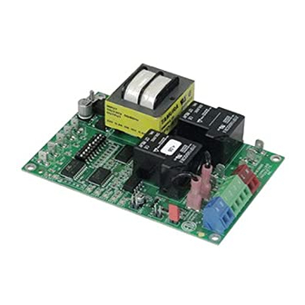
NEW X.06 VERSION UC1 BOARD FEATURES
New LED # 6 RED
115V power supplied
to UC1 L & N terminals
LED # 2 now BLUE
(previously GREEN)
LED # 5 RED With no
call for heat, flashes 3
seconds on / 3 seconds
off if microcontroller is
working properly.
©2005 TJERNLUND PRODUCTS, INC. ALL RIGHTS RESERVED
P1 P2
C GND F
LED 6 (RED) POWER LED
(1
9)
LED 1 (AMBER)
LED 2 (BLUE)
LED 3 (GREEN)
LED 4 (RED)
LED 5 (RED)
DRY
APPLIANCE
VENTER
INTERLOCK
MOTOR
RELAY
RELAY
24 V
115 V
J1
J2
XL
XN
N
M
A B 1 2 3 4 L N
REV. B 07/05
MTR
Advertisement
Table of Contents

Related Manuals for TJERNLUND SS1 SIDESHOT WITH UC1 UNIVERSAL CONTROL (VERSION X.06) 8504102 REV D 0705


Summary of Contents for TJERNLUND SS1 SIDESHOT WITH UC1 UNIVERSAL CONTROL (VERSION X.06) 8504102 REV D 0705
- Page 1 LED #3 (Green) Power switched to Venter motor from L to MTR & M. LED #4 (Red) Status / Fault indicator. LED #5 (Red) Used as a status indicator. LED #6 (Red) 115 VAC power supplied to board. P/N: 8505017 ©2005 TJERNLUND PRODUCTS, INC. ALL RIGHTS RESERVED REV. B 07/05...
- Page 2 LED STATUS INDICATORS LED #4 & #5 (Red) Flashing Alternately = Venter in Pre-purge. (Pre-Purge options 0, 5, 20, 35 seconds) LED #4 & #5 (Red) Flashing in Unison = Venter in Post-Purge. (Post-Purge options 0, 30 seconds or 1, 2, 4, 8, 16 minutes) LED #4 Flashes Continuously* = Fan Prover opened for more than 10 seconds during burner cycle.
-
Page 3: Installation Instructions
MENT, SERVICE OR MAINTENANCE POSSIBLY RESULTING IN FIRE, ELECTRI- CAL SHOCK, CARBON MONOXIDE POISONING, EXPLOSION, OR PERSONAL INJURY OR PROPERTY DAMAGE. DO NOT DESTROY. PLEASE READ CAREFULLY AND KEEP IN A SAFE PLACE FOR FUTURE REFERENCE. Copyright © 2005, Tjernlund Products, Inc. All rights reserved P/N 8504102... -
Page 4: Table Of Contents
Tjernlund Products welcomes your comments and questions. Address all correspondence to: Customer Service • Tjernlund Products, Inc. • 1601 Ninth Street • White Bear Lake, MN 55110-6794 Call us toll free at 800-255-4208, visit our web site @ www.tjernlund.com or email us at fanmail@tjfans.com. TABLE OF CONTENTS Page (s) Description and Specifications ............................1, 2... -
Page 5: Installation Restrictions
SPECIFICATIONS Motor: 115/1/60, 3300 RPM, 212 watts, 2.28 FLA Fan Proving Switch: Non-adjustable set point of -.05" W.C. High Limit: Manual reset, N/C contacts, open at 135 o F + 10 o F. UC1 Universal Control: See UC1 Universal Control Board Features on page 4. Pre-Purge: Options (0, 5, 20, 35 seconds);... -
Page 6: Cautions
CAUTIONS The SS1 must be installed by a qualified installer (an individual properly licensed and/or trained) in accordance with all local codes or, in their absence, in accordance with the appropriate National Fire Protection Association #31, #54, #211 and the National Electrical Code. -
Page 7: Sideshot ® With Integral Uc1 Universal Control Board Features
P1 - P2 SAFETY CIRCUIT C, GND, F AUXILIARY DEVICE TERMINALS COMMUNICATION TERMINALS 1 mA @ 5VDC. 2 mA @ 5VDC. For Tjernlund MAC1E or SEE WARNING # 1. MAC4E auxiliary devices. SEE WARNING # 1. DIP SWITCH SETTINGS Pre-Purge (1-2) -
Page 8: Pre / Post-Purge & Pre-Cycle Prover Status Check Settings
LED FAULT INDICATORS Fault conditions are indicated by counting the number of times LED #4 (Red) flashes. LED #4 Flashes 2 Times Fan Prover was in electrically closed position prior to venter operation. LED #4 Flashes 3 Times* Fan Prover does not close within 60 seconds after call for heat. LED #4 Flashes 4 Times* Fan Prover did not re-close after 10 minutes of Venter operation. -
Page 9: Termination Clearances
P1 & P2 PRE-CYCLE FAN PROVER STATUS CHECK Pre-Cycle The Pre-Cycle Prover Status Check is deactivated from the factory on the SS1 Series. Because of Prover Status the low set point of the SS1 Fan Prover (as low as .03" w.c.) cross winds may cause the Fan Check Deactivated Prover to close prior to a call for heat. -
Page 10: Installation
INSTALLATION Tools required: • Reciprocating Saw • 1/2", 7/16",5/8" Wrench • Drill and 1/8", 1/4", 1/2" Bits • 1/4" Masonry Drill Bit • Blade Screwdriver • 1/4", 5/16”, 11/32" Nut Runner or Socket • Wire Cutter/Stripper • Hammer • Tube Cutter INSTALLING VENT HOOD TERMINUS 1. -
Page 11: Installation Of Rain Shield
DIAGRAM D DIAGRAM E NOTE: For mounting on vinyl or lap siding a wood frame with 1” x 1 1/2” on the sides and top and 1” x 2” material on bottom can be utilized on exterior wall. This will provide a flush mounting surface for the hood and a nicely finished look with “J”... -
Page 12: Plenum Installation
NOTCH BRACING It is recommended and local codes may dictate that the joist be reinforced as outlined below. Bracing of the rim joist is not necessary. 1. Cut two 2 x 4 pieces of wood 28 inches in length. 2. Center both pieces on each side of the floor joist above the notch and drive 8 16D or larger nails into each piece, (See Diag. H) DIAGRAM H CONNECTING THE PLENUM TO THE VENT HOOD NOTE: Cut any nails which are protruding downward from the subfloor that may come in contact with the SideShot. -
Page 13: Installation Of Vent Pipe
DIAGRAM J IMPORTANT: Adjust SS1 mounting bracket for a slight downward pitch towards exit terminal. INSTALLATION OF VENT PIPE If installing the SideShot Vent System on an oil or gas appliance which is not equipped with a draft hood or draft diverter, a baro- metric draft control must be used. - Page 14 4. Using a tube cutter, cut the sensing tube 2" from the elbow directed at the vent pipe inlet collar, (See Diagram L). Discard the cut off section of metal tube. 5. Attach the vent pipe inlet collar to the rear inlet port making sure that the sensing tube is orientated as shown, (See Diagram M). NOTE: Alignment marks on the inlet collar and plenum casing must match.
-
Page 15: Electrical Wiring
The steps listed under each diagram are intended as a supplement to the diagram. Wiring colors or designations may vary by manufacturer. If you are unable to wire the SS1 as outlined in these instructions, call Tjernlund’s Customer Service Department toll free at 1-800-255-4208 for assistance. - Page 16 SIDESHOT WITH INTEGRAL UC1 UNIVERSAL CONTROL CONNECTED TO A HONEYWELL R8184 SERIES OR EQUIVALENT PRIMARY CONTROL CONNECT TO L1 OR B1 IMPORTANT: RED JUMPER POSITION MUST BE THE SAME BLACK AS APPLIANCE INTERLOCK VOLTAGE. ORANGE WHITE CALL IGNITION TRANS JUMPER HONEYWELL WHITE R8184 SERIES...
- Page 17 SIDESHOT WITH INTEGRAL UC1 UNIVERSAL CONTROL CONNECTED WITH AN AQUASTAT IMPORTANT: LEGEND: RED JUMPER POSITION MUST BE THE SAME 115 VAC AQUASTAT AS APPLIANCE INTERLOCK VOLTAGE. D/N 9183046-7 CALL JUMPER SUPPLY LINE VOLTAGE OIL BURNER 115 VAC PRIMARY CONTROL, BURNER 50/60 Hz RELAY OR GAS VALVE GROUND...
-
Page 18: Wiring To Oil Fired Equipment
SIDESHOT WITH INTEGRAL UC1 UNIVERSAL CONTROL CONNECTED TO AN OIL-FIRED FURNACE WITH A HONEYWELL T87 OR EQUIVALENT NON-POWERED THERMOSTAT IMPORTANT: RED JUMPER POSITION MUST BE THE SAME AS APPLIANCE INTERLOCK VOLTAGE. HONEYWELL T87 OR EQUIVALENT NON-POWERED THERMOSTAT IMPORTANT: REMOVE JUMPER TO AVOID BACKFEEDS OR SHORT CIRCUITS. -
Page 19: Wiring To Gas Fired Appliance
SIDESHOT WITH INTEGRAL UC1 UNIVERSAL CONTROL CONNECTED WITH A SINGLE ZONE 24 VAC THERMOSTAT IMPORTANT: RED JUMPER POSITION MUST BE THE SAME AS APPLIANCE INTERLOCK VOLTAGE. THERMOSTAT CALL JUMPER SUPPLY INTERNAL CONTROL LEGEND: 115 VAC OF FURNACE 50/60 Hz 115 VAC GROUND 24 VAC IMPORTANT:... -
Page 20: Draft Adjustment Procedure (Oil)
SIDESHOT WITH INTEGRAL UC1 UNIVERSAL CONTROL CONNECTED WITH A 24 OR 115 VAC STANDING PILOT IMPORTANT: RED JUMPER POSITION MUST BE THE SAME AS APPLIANCE INTERLOCK VOLTAGE. INTERNAL CONTROLS OF FURNACE/BOILER Aquastat T-stat CALL JUMPER SUPPLY 115 VAC 50/60 Hz LEGEND: GROUND 115 VAC... - Page 21 Do not allow heating system to run at less than a -.02” W.C. over fire draft or at a CO level that is less than a 1% reduction from the value measured at a trace of smoke and a -.02” W.C. over fire draft. If these parameters are unobtainable, contact Tjernlund at 1-800-255-4208 for Technical Assistance.
-
Page 22: Draft Adjustment Procedure (Gas)
IMPORTANT: The following paragraph describes the initial draft adjustment. It may be necessary to make a slight readjustment to compensate for various conditions: wind, vent connector resistance, negative building pressure and multiple appliances. ASHRAE lists the average design factor for wind loads in North America at 15 MPH. Refer to the Draft Adjustment Chart on Page 17. -
Page 23: Troubleshooting Oil Odors
Accessory air intakes are available that connect to the burner motor, using it to pull in the outdoor air. The Tjernlund IN-FORCER Combustion Air Intake tempers the raw outdoor air as it is delivered to the burner. - Page 24 LED FAULT INDICATORS Fault conditions are indicated by counting the number of times LED #4 (Red) flashes. LED #4 Flashes 2 Times Fan Prover was in electrically closed position prior to venter operation. LED #4 Flashes 3 Times* Fan Prover does not close within 60 seconds after call for heat. LED #4 Flashes 4 Times* Fan Prover did not re-close after 10 minutes of Venter operation.
-
Page 25: Maintenance
Voltage should be the same in both cases, if not rewire per appropriate diagram or confirm burner control(s) are functioning prop- erly. NOTE: If a different voltage source is provided to terminal 3 which is switched to terminal 4 or when using the A-B dry con- tacts, voltage measurements may not apply. -
Page 26: Warranty & Replacement Parts
TJERNLUND LIMITED TWO YEAR WARRANTY Tjernlund Products, Inc. warrants to the original purchaser of this product that the product will be free from defects due to faulty material or workmanship for a period of (2) years from the date of original purchase or delivery to the original purchaser, whichever is earlier. Remedies under this warranty are limited to repairing or replacing, at our option, any product which shall, within the above stated warranty period, be returned to Tjernlund Products, Inc.
Need help?
Do you have a question about the SS1 SIDESHOT WITH UC1 UNIVERSAL CONTROL (VERSION X.06) 8504102 REV D 0705 and is the answer not in the manual?
Questions and answers