TJERNLUND HS3,4,5 WITH UC1 UNIVERSAL CONTROL (VERSION X.02) 8504111 REV 0902 Manual
Side wall vent systems for natural gas or lp
Hide thumbs
Also See for HS3,4,5 WITH UC1 UNIVERSAL CONTROL (VERSION X.02) 8504111 REV 0902:
- Manual (18 pages) ,
- Dimensions (3 pages) ,
- System reference manual (6 pages)
Table of Contents
Advertisement
Quick Links
Download this manual
See also:
Manual
FOR NATURAL GAS OR LP
FAN PROVER
UC1
OWNER INSTRUCTIONS, DO NOT DESTROY
!
Recognize this symbol as an indication of important Safety Information!
NOTE: FLUE GAS TEMPERATURES MUST NOT EXCEED
o
600
F AT VENT SYSTEM INLET.
THESE INSTRUCTIONS ARE INTENDED AS AN AID TO QUALIFIED, LICENSED
SERVICE PERSONNEL FOR PROPER INSTALLATION, ADJUSTMENT AND
OPERATION OF THIS UNIT. READ THESE INSTRUCTIONS THOROUGHLY
BEFORE ATTEMPTING INSTALLATION OR OPERATION. FAILURE TO FOLLOW
THESE INSTRUCTIONS MAY RESULT IN IMPROPER INSTALLATION, ADJUST-
MENT, SERVICE OR MAINTENANCE POSSIBLY RESULTING IN FIRE, ELECTRI-
CAL SHOCK, CARBON MONOXIDE POISONING, EXPLOSION, PERSONAL
INJURY OR PROPERTY DAMAGE.
DO NOT DESTROY. PLEASE READ CAREFULLY AND KEEP
IN A SAFE PLACE ON JOB SITE FOR FUTURE REFERENCE.
Copyright © 2002, Tjernlund Products, Inc. All rights reserved.
TJERNLUND PRODUCTS, INC.
1601 Ninth Street • White Bear Lake, MN 55110-6794
PHONE (800) 255-4208 • (651) 426-2993 • FAX (651) 426-9547
Visit our web site • www.tjernlund.com
VENTER
REV. 9/02
MODELS
HS3
HS4
HS5
INCLUDES NEW UC1
UNIVERSAL CONTROL
P/N 8504111
Advertisement
Table of Contents

Related Manuals for TJERNLUND HS3,4,5 WITH UC1 UNIVERSAL CONTROL (VERSION X.02) 8504111 REV 0902


Summary of Contents for TJERNLUND HS3,4,5 WITH UC1 UNIVERSAL CONTROL (VERSION X.02) 8504111 REV 0902
- Page 1 CAL SHOCK, CARBON MONOXIDE POISONING, EXPLOSION, PERSONAL INJURY OR PROPERTY DAMAGE. DO NOT DESTROY. PLEASE READ CAREFULLY AND KEEP IN A SAFE PLACE ON JOB SITE FOR FUTURE REFERENCE. Copyright © 2002, Tjernlund Products, Inc. All rights reserved. P/N 8504111...
-
Page 2: Table Of Contents
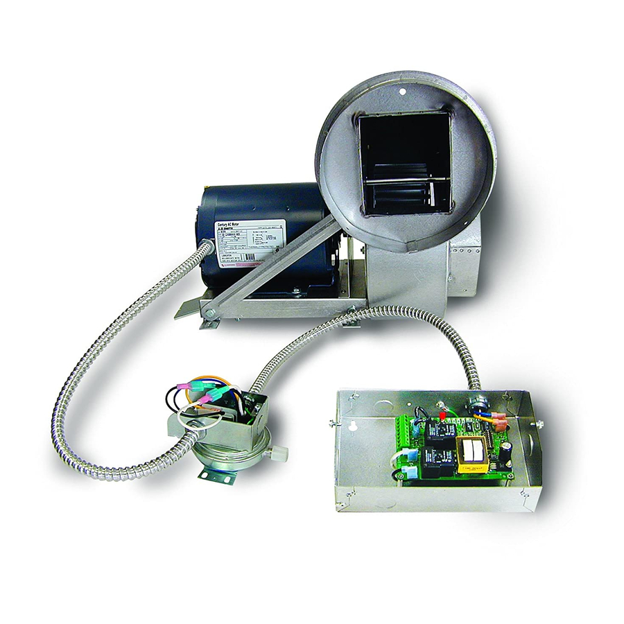
DESCRIPTION The Tjernlund Power Venter models HS3, HS4 and HS5 are designed to Side Wall or Vertically vent Natural and LP Gas appliances. After each burner cycle the Venter will continue to operate in post-purge mode to purge the heater and vent of residual flue gases. A factory post-purge time is set at 2 minutes and is adjustable up 16 minutes, see “Pre / Post-purge Settings”... - Page 3 CIRCUIT PROTECTION PROVIDED BY INSTALLER 150 mA MAX @ 120 VAC, 50/60 Hz XL / XN CAN ONLY BE CONNECTED TO TJERNLUND-SPECIFIED AUXILIARY DEVICE ADD VENTER MOTOR UC1 CONTROL DURING OPERATION THE CONTROL USES 50 mA MAX @ 120 VAC...
-
Page 4: Installation Restrictions
INSTALLATION RESTRICTIONS 1. The Power Venter may only be installed on Natural Gas or LP Gas appliances. 2. The Power Venter may not be installed on incinerators, incinerating toilets, condensing-type appliances or solid-fuel burning appliances. 3. The Power Venter shall not be installed on an appliance with an automatic valve having a manual opener unless the manual opener has been rendered inoperative or the automatic valve has been replaced with a valve not equipped with a manual opener. -
Page 5: Uc1 Universal Control Board Features
P1 - P2 SAFETY CIRCUIT C, GND, F AUXILIARY DEVICE TERMINALS COMMUNICATION TERMINALS 1 mA @ 5VDC. 2 mA @ 5VDC. For Tjernlund MAC1E or SEE WARNING # 1. MAC4E auxiliary devices. SEE WARNING # 1. DIP SWITCH SETTINGS Pre-Purge (1-2) -
Page 6: Pre / Post-Purge & Prover Status Check Settings
PRE / POST PURGE AND PROVER STATUS CHECK DIP SWITCH SETTINGS Remove power to UC1 and heating equipment when installing, servicing or changing dip switch settings. Failure to do so may result in personal injury and/or equipment damage. LED #5 (RED) should not be on if 115 VAC supply power is removed from the control. Pre-purge Used for a Venter with longer vent runs to get draft fully established throughout the vent system prior to burner ignition. -
Page 7: Vent Hood Location
VENT HOOD LOCATION This section only applies if using a Power Venter to Sidewall vent. If using Power Venter to exhaust the flue gases vertically, skip to the section titled “POWER VENTER MOUNTING” below. If possible, locate the Vent Hood on a wall that does not face the direction of prevailing winds. This will diminish the possibility of appliance interruption during periods of extreme winds. -
Page 8: Vent Pipe Installation
VENT PIPE INSTALLATION If Installing the Power Venter on an appliance not equipped with a draft hood or draft diverter (e.g. Power Burners, Induced Draft), a barometric draft control must be added. The barometric draft control must be the same size as the flue outlet and installed as close as possible to the appliance. -
Page 9: Wiring
The steps listed under each diagram are intended as a supplement to the diagram. Wiring colors or designations may vary by manu- facturer. If you are unable to wire the UC1 as outlined in these instructions, call Tjernlund’s Customer Service Department toll free at 1-800-255-4208 for assistance. -
Page 10: Wiring Connections From Uc1 To Fan Prover And Motor
LINE (1 - 2) PROVER 115 VAC 24 VAC NEUTRAL COMMON POST-PURGE SETTINGS INTERLOCK (3 - 8) APPROVED FOR TJERNLUND RELAY SUPPLY MAC1E OR MAC4E 115 VAC OPEN PROVER OPTION AUXILIARY 50/60 Hz DEVICES. DO NOT CONNECT POWER TO P1, P2, C, GND OR F. -
Page 11: Wiring Diagrams With A Single Gas Appliance
UC1 UNIVERSAL CONTROL CONNECTED WITH A 24 VAC ELECTRONIC IGNITION MODULE IMPORTANT: RED JUMPER POSITION MUST BE THE SAME AS APPLIANCE INTERLOCK VOLTAGE. SPARK CALL JUMPER SUPPLY 24V GND 115 VAC 50/60 Hz BNR GND GROUND MV / PV IMPORTANT: LEGEND: CRIMP GROUND WIRE TO GROUNDING 115 VAC... - Page 12 UC1 UNIVERSAL CONTROL CONNECTED WITH AN AQUASTAT IMPORTANT: LEGEND: RED JUMPER POSITION MUST BE THE SAME 115 VAC AQUASTAT AS APPLIANCE INTERLOCK VOLTAGE. D/N 9183046-7 CALL JUMPER SUPPLY LINE VOLTAGE OIL BURNER LINE VOLTAGE BURNER 115 VAC PRIMARY CONTROL, BURNER RELAY OR GAS VALVE 50/60 Hz RELAY OR GAS VALVE...
-
Page 13: Uc1 Operation Check, Draft Adjustment And Combustion Air
UC1 UNIVERSAL CONTROL AND WHKE INTERLOCK KIT CONNECTED WITH A MILLIVOLT APPLIANCE and WHKE Millivolt Interlock Kit IMPORTANT: RED JUMPER POSITION MUST BE THE SAME AS APPLIANCE INTERLOCK VOLTAGE. VALVE LEGEND: 115 VAC CALL 5 VDC JUMPER BOARD- WHKE GAS LINEAR LIMIT GENERATED PRESSURE... - Page 14 In some cases this is a false assumption, because many older buildings have been made "tight" due to weatheriza- tion. Size the combustion air opening(s) into the appliance room as outlined local or national codes. Tjernlund’s IN-FORCER Combustion Air Intake Systems provide a convenient interlocked way to provide combustion air to the equipment room. When installing a Power Venter it is not necessary to supply any more combustion air than normally required when conventional venting.
-
Page 15: Maintenance
Extreme caution must be exercised to prevent injury. If you are unable to determine the defective part with the use of this guide, call your Tjernlund distributor or Tjernlund Products direct at 1-800-255-4208 for further assistance. -
Page 16: Warranty & Replacement Parts
TJERNLUND LIMITED ONE YEAR WARRANTY Tjernlund Products, Inc. warrants to the original purchaser of this product that the product will be free from defects due to faulty material or workmanship for a period of (1) year from the date of origi- nal purchase or delivery to the original purchaser, whichever is earlier.
Need help?
Do you have a question about the HS3,4,5 WITH UC1 UNIVERSAL CONTROL (VERSION X.02) 8504111 REV 0902 and is the answer not in the manual?
Questions and answers