TJERNLUND HS3,4,5 WITH UC1 UNIVERSAL CONTROL (VERSION X.06) 8504111 REV C 0705 Manual
Side wall vent systems for natural gas or lp
Hide thumbs
Also See for HS3,4,5 WITH UC1 UNIVERSAL CONTROL (VERSION X.06) 8504111 REV C 0705:
- Manual (16 pages) ,
- Dimensions (3 pages) ,
- System reference manual (6 pages)
Table of Contents
Advertisement
Quick Links
IMPORTANT!!! UC1 BOARD VERSION X.06 UPDATES
IMPORTANT: This upgraded circuit board features:
A new #6 power LED
Constant red when 115 VAC is supplied to L & N.
A new color for the #2 LED
Constant blue when fan prover safety circuit is closed.
A revised #5 LED
With no call for heat present, flashes 3 seconds on /
3 seconds off if microcontroller is working properly.
IMPORTANT:
For 950-8804 UC1 Replacement Board Kits: If this is a 950-8804 UC1 board kit and you are replacing an existing UC1 board with this
new board, note Dip Switch settings on existing UC1 circuit board so that those same settings can be positioned on this replacement circuit
board. NOTE: Adhere appropriate included label over existing label in UC1 or SideShot electrical box. Also adhere "Checking Memory for
Last Fault Code" sticker on inside of UC1 or SideShot SS1 Series electrical box. On SS2 Series adhere to underside of electrical box.
For SideShot Series SS1 Models: The Pre-Cycle Prover Status Check is deactivated from the factory on the SS1 Series. Because of the
low set point of the SS1 Fan Prover (as low as .03" w.c.) cross winds may cause the Fan Prover to close prior to a call for heat. Activating the
Prover Status Check on the SS1 may cause nuisance lockouts. Important: Deactivate the Pre-Cycle Prover status check if installing this board
on a new or existing SS1 installation by pushing the #9 dip switch up or "ON" to disable.
For Draft Inducers with the UC1: Natural draft or winds may be sufficient to close the fan prover switch contacts prior to a call for heat
when using the PS1505 fan prover with a draft inducer. Keeping the Pre-Cycle Prover Status Check activated may cause nuisance lockouts.
Important: Deactivate the Pre-Cycle Prover status check if installing this board on a new or existing draft inducer installation by pushing the #9
dip switch up or "ON" to disable.
LED INDICATOR LIGHTS
LED #1 (Amber) Appliance call for heat.
LED #2 (Blue)
Safety circuit through P1 & P2 (Venter Fan Prover and/or High Limit). Indicates Venter prover is closed during run cycle.
Burner circuit is energized with Interlock Relay contact closure from terminal 3 to 4.
LED #3 (Green) Power switched to Venter motor from L to MTR & M.
LED #4 (Red)
Status / Fault indicator.
LED #5 (Red)
Used as a status indicator.
LED #6 (Red)
115 VAC power supplied to board.
P/N: 8505017
TJERNLUND PRODUCTS, INC.
1601 Ninth Street • White Bear Lake, MN 55110-6794
PHONE (800) 255-4208 • (651) 426-2993 • FAX (651) 426-9547
Visit our web site • www.tjernlund.com
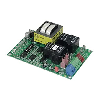
NEW X.06 VERSION UC1 BOARD FEATURES
New LED # 6 RED
115V power supplied
to UC1 L & N terminals
LED # 2 now BLUE
(previously GREEN)
LED # 5 RED With no
call for heat, flashes 3
seconds on / 3 seconds
off if microcontroller is
working properly.
©2005 TJERNLUND PRODUCTS, INC. ALL RIGHTS RESERVED
P1 P2
C GND F
LED 6 (RED) POWER LED
(1
9)
LED 1 (AMBER)
LED 2 (BLUE)
LED 3 (GREEN)
LED 4 (RED)
LED 5 (RED)
DRY
APPLIANCE
VENTER
INTERLOCK
MOTOR
RELAY
RELAY
24 V
115 V
J1
J2
XL
XN
N
M
A B 1 2 3 4 L N
REV. B 07/05
MTR
Advertisement
Table of Contents

Related Manuals for TJERNLUND HS3,4,5 WITH UC1 UNIVERSAL CONTROL (VERSION X.06) 8504111 REV C 0705


Summary of Contents for TJERNLUND HS3,4,5 WITH UC1 UNIVERSAL CONTROL (VERSION X.06) 8504111 REV C 0705
- Page 1 LED #3 (Green) Power switched to Venter motor from L to MTR & M. LED #4 (Red) Status / Fault indicator. LED #5 (Red) Used as a status indicator. LED #6 (Red) 115 VAC power supplied to board. P/N: 8505017 ©2005 TJERNLUND PRODUCTS, INC. ALL RIGHTS RESERVED REV. B 07/05...
- Page 2 LED STATUS INDICATORS LED #4 & #5 (Red) Flashing Alternately = Venter in Pre-purge. (Pre-Purge options 0, 5, 20, 35 seconds) LED #4 & #5 (Red) Flashing in Unison = Venter in Post-Purge. (Post-Purge options 0, 30 seconds or 1, 2, 4, 8, 16 minutes) LED #4 Flashes Continuously* = Fan Prover opened for more than 10 seconds during burner cycle.
- Page 3 CAL SHOCK, CARBON MONOXIDE POISONING, EXPLOSION, PERSONAL INJURY OR PROPERTY DAMAGE. DO NOT DESTROY. PLEASE READ CAREFULLY AND KEEP IN A SAFE PLACE ON JOB SITE FOR FUTURE REFERENCE. Copyright © 2005, Tjernlund Products, Inc. All rights reserved. P/N 8504111...
-
Page 4: Table Of Contents
DESCRIPTION The Tjernlund Power Venter models HS3, HS4 and HS5 are designed to Side Wall or Vertically vent Natural and LP Gas appliances. After each burner cycle the Venter will continue to operate in post-purge mode to purge the heater and vent of residual flue gases. A factory post-purge time is set at 2 minutes and is adjustable up 16 minutes, see “Pre / Post-purge Settings”... - Page 5 CIRCUIT PROTECTION PROVIDED BY INSTALLER 150 mA MAX @ 120 VAC, 50/60 Hz XL / XN CAN ONLY BE CONNECTED TO TJERNLUND-SPECIFIED AUXILIARY DEVICE ADD VENTER MOTOR UC1 CONTROL DURING OPERATION THE CONTROL USES 50 mA MAX @ 120 VAC...
-
Page 6: Installation Restrictions
INSTALLATION RESTRICTIONS 1. The Power Venter may only be installed on Natural Gas or LP Gas appliances. 2. The Power Venter may not be installed on incinerators, incinerating toilets, condensing-type appliances or solid-fuel burning appliances. 3. The Power Venter shall not be installed on an appliance with an automatic valve having a manual opener unless the manual opener has been rendered inoperative or the automatic valve has been replaced with a valve not equipped with a manual opener. -
Page 7: Uc1 Universal Control Board Features
P1 - P2 SAFETY CIRCUIT C, GND, F AUXILIARY DEVICE TERMINALS COMMUNICATION TERMINALS 1 mA @ 5VDC. 2 mA @ 5VDC. For Tjernlund MAC1E or SEE WARNING # 1. MAC4E auxiliary devices. SEE WARNING # 1. DIP SWITCH SETTINGS Pre-Purge (1-2) -
Page 8: Pre / Post-Purge & Prover Status Check Settings
LED FAULT INDICATORS Fault conditions are indicated by counting the number of times LED #4 (Red) flashes. LED #4 Flashes 2 Times Fan Prover was in electrically closed position prior to venter operation. LED #4 Flashes 3 Times* Fan Prover does not close within 60 seconds after call for heat. LED #4 Flashes 4 Times* Fan Prover did not re-close after 10 minutes of Venter operation. -
Page 9: Vent Hood Location
P1 & P2 PRE-CYCLE FAN PROVER STATUS CHECK Pre-Cycle The Pre-Cycle Prover Status Check is activated from the factory. When activated the UC1 Prover Status Universal Control checks across P1 & P2 safety circuit (Venter Fan Prover) to verify that the Fan Check Activated Prover switch is “Open”... -
Page 10: Vent Pipe Installation
VENT PIPE INSTALLATION If Installing the Power Venter on an appliance not equipped with a draft hood or draft diverter (e.g. Power Burners, Induced Draft), a barometric draft control must be added. The barometric draft control must be the same size as the flue outlet and installed as close as possible to the appliance. -
Page 11: Wiring
The steps listed under each diagram are intended as a supplement to the diagram. Wiring colors or designations may vary by manu- facturer. If you are unable to wire per these instructions, call Tjernlund’s Technical Service toll free at 1-800-255-4208 for assistance. -
Page 12: Wiring Connections From Uc1 To Fan Prover And Motor
PRE-PURGE SETTINGS CALL FOR (1 - 2) PROVER COMMON / HEAT NEUTRAL POST-PURGE SETTINGS INTERLOCK (3 - 8) APPROVED CALL FOR TJERNLUND RELAY SUPPLY MAC1E OR MAC4E 115 VAC OPEN PROVER OPTION AUXILIARY 50/60 Hz DEVICES. DO NOT CONNECT POWER TO P1, P2, C, GND OR F. -
Page 13: Wiring Diagrams With A Single Gas Appliance
UC1 UNIVERSAL CONTROL CONNECTED WITH A 24 VAC ELECTRONIC IGNITION MODULE IMPORTANT: RED JUMPER POSITION MUST BE THE SAME AS APPLIANCE INTERLOCK VOLTAGE. SPARK CALL JUMPER SUPPLY 24V GND 115 VAC 50/60 Hz BNR GND GROUND MV / PV IMPORTANT: LEGEND: CRIMP GROUND WIRE TO GROUNDING 115 VAC... - Page 14 UC1 UNIVERSAL CONTROL CONNECTED WITH AN AQUASTAT IMPORTANT: LEGEND: RED JUMPER POSITION MUST BE THE SAME 115 VAC AS APPLIANCE INTERLOCK VOLTAGE. AQUASTAT D/N 9183046-7 CALL JUMPER SUPPLY LINE VOLTAGE OIL BURNER LINE VOLTAGE BURNER 115 VAC PRIMARY CONTROL, BURNER RELAY OR GAS VALVE 50/60 Hz RELAY OR GAS VALVE...
-
Page 15: Uc1 Operation Check, Draft Adjustment And Combustion Air
UC1 UNIVERSAL CONTROL AND WHKE INTERLOCK KIT CONNECTED WITH A MILLIVOLT APPLIANCE IMPORTANT: RED JUMPER POSITION MUST BE THE SAME AS APPLIANCE INTERLOCK VOLTAGE. VALVE LEGEND: 115 VAC CALL 5 VDC JUMPER BOARD- WHKE GAS LINEAR LIMIT GENERATED PRESSURE SPILL SWITCH POWER. -
Page 16: Maintenance
In some cases this is a false assumption, because many older buildings have been made "tight" due to weatheriza- tion. Size the combustion air opening(s) into the appliance room as outlined local or national codes. Tjernlund’s IN-FORCER Combustion Air Intake Systems provide a convenient interlocked way to provide combustion air to the equipment room. When installing a Power Venter it is not necessary to supply any more combustion air than normally required when conventional venting. -
Page 17: Troubleshooting
Extreme caution must be exercised to prevent injury. If you are unable to determine the defective part with the use of this guide, call your Tjernlund distributor or Tjernlund Products at 1-800-255-4208 for further assistance. IMPORTANT: If the call for heat interlock signal or 115 VAC power is removed, the UC1 board will reset and any fault, if present, will be stored in memory instead of displayed. -
Page 18: Warranty & Replacement Parts
TJERNLUND LIMITED ONE YEAR WARRANTY Tjernlund Products, Inc. warrants to the original purchaser of this product that the product will be free from defects due to faulty material or workmanship for a period of (1) year from the date of origi- nal purchase or delivery to the original purchaser, whichever is earlier.
Need help?
Do you have a question about the HS3,4,5 WITH UC1 UNIVERSAL CONTROL (VERSION X.06) 8504111 REV C 0705 and is the answer not in the manual?
Questions and answers