TJERNLUND HSJ, 1, 2 WITH UC1 UNIVERSAL CONTROL (VERSION X.06) 8504106 REV C 0705 Manual
Side wall vent system for natural gas, lp or oil
Hide thumbs
Also See for HSJ, 1, 2 WITH UC1 UNIVERSAL CONTROL (VERSION X.06) 8504106 REV C 0705:
- Manual (4 pages) ,
- Dimensions (3 pages) ,
- System reference manual (6 pages)
Table of Contents
Advertisement
IMPORTANT!!! UC1 BOARD VERSION X.06 UPDATES
IMPORTANT: This upgraded circuit board features:
A new #6 power LED
Constant red when 115 VAC is supplied to L & N.
A new color for the #2 LED
Constant blue when fan prover safety circuit is closed.
A revised #5 LED
With no call for heat present, flashes 3 seconds on /
3 seconds off if microcontroller is working properly.
IMPORTANT:
For 950-8804 UC1 Replacement Board Kits: If this is a 950-8804 UC1 board kit and you are replacing an existing UC1 board with this
new board, note Dip Switch settings on existing UC1 circuit board so that those same settings can be positioned on this replacement circuit
board. NOTE: Adhere appropriate included label over existing label in UC1 or SideShot electrical box. Also adhere "Checking Memory for
Last Fault Code" sticker on inside of UC1 or SideShot SS1 Series electrical box. On SS2 Series adhere to underside of electrical box.
For SideShot Series SS1 Models: The Pre-Cycle Prover Status Check is deactivated from the factory on the SS1 Series. Because of the
low set point of the SS1 Fan Prover (as low as .03" w.c.) cross winds may cause the Fan Prover to close prior to a call for heat. Activating the
Prover Status Check on the SS1 may cause nuisance lockouts. Important: Deactivate the Pre-Cycle Prover status check if installing this board
on a new or existing SS1 installation by pushing the #9 dip switch up or "ON" to disable.
For Draft Inducers with the UC1: Natural draft or winds may be sufficient to close the fan prover switch contacts prior to a call for heat
when using the PS1505 fan prover with a draft inducer. Keeping the Pre-Cycle Prover Status Check activated may cause nuisance lockouts.
Important: Deactivate the Pre-Cycle Prover status check if installing this board on a new or existing draft inducer installation by pushing the #9
dip switch up or "ON" to disable.
LED INDICATOR LIGHTS
LED #1 (Amber) Appliance call for heat.
LED #2 (Blue)
Safety circuit through P1 & P2 (Venter Fan Prover and/or High Limit). Indicates Venter prover is closed during run cycle.
Burner circuit is energized with Interlock Relay contact closure from terminal 3 to 4.
LED #3 (Green) Power switched to Venter motor from L to MTR & M.
LED #4 (Red)
Status / Fault indicator.
LED #5 (Red)
Used as a status indicator.
LED #6 (Red)
115 VAC power supplied to board.
P/N: 8505017
TJERNLUND PRODUCTS, INC.
1601 Ninth Street • White Bear Lake, MN 55110-6794
PHONE (800) 255-4208 • (651) 426-2993 • FAX (651) 426-9547
Visit our web site • www.tjernlund.com
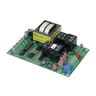
NEW X.06 VERSION UC1 BOARD FEATURES
New LED # 6 RED
115V power supplied
to UC1 L & N terminals
LED # 2 now BLUE
(previously GREEN)
LED # 5 RED With no
call for heat, flashes 3
seconds on / 3 seconds
off if microcontroller is
working properly.
©2005 TJERNLUND PRODUCTS, INC. ALL RIGHTS RESERVED
P1 P2
C GND F
LED 6 (RED) POWER LED
(1
9)
LED 1 (AMBER)
LED 2 (BLUE)
LED 3 (GREEN)
LED 4 (RED)
LED 5 (RED)
DRY
APPLIANCE
VENTER
INTERLOCK
MOTOR
RELAY
RELAY
24 V
115 V
J1
J2
XL
XN
N
M
A B 1 2 3 4 L N
REV. B 07/05
MTR
Advertisement
Table of Contents

Related Manuals for TJERNLUND HSJ, 1, 2 WITH UC1 UNIVERSAL CONTROL (VERSION X.06) 8504106 REV C 0705


Summary of Contents for TJERNLUND HSJ, 1, 2 WITH UC1 UNIVERSAL CONTROL (VERSION X.06) 8504106 REV C 0705
- Page 1 LED #3 (Green) Power switched to Venter motor from L to MTR & M. LED #4 (Red) Status / Fault indicator. LED #5 (Red) Used as a status indicator. LED #6 (Red) 115 VAC power supplied to board. P/N: 8505017 ©2005 TJERNLUND PRODUCTS, INC. ALL RIGHTS RESERVED REV. B 07/05...
- Page 2 LED STATUS INDICATORS LED #4 & #5 (Red) Flashing Alternately = Venter in Pre-purge. (Pre-Purge options 0, 5, 20, 35 seconds) LED #4 & #5 (Red) Flashing in Unison = Venter in Post-Purge. (Post-Purge options 0, 30 seconds or 1, 2, 4, 8, 16 minutes) LED #4 Flashes Continuously* = Fan Prover opened for more than 10 seconds during burner cycle.
- Page 3 VICE OR MAINTENANCE POSSIBLY RESULTING IN FIRE, ELECTRICAL SHOCK, CARBON MONOXIDE POISONING, EXPLOSION, OR PERSONAL INJURY OR PROPERTY DAMAGE. DO NOT DESTROY. PLEASE READ CAREFULLY AND KEEP IN A SAFE PLACE ON JOB SITE FOR FUTURE REFERENCE. Copyright © 2005, Tjernlund Products, Inc. All rights reserved. P/N 8504106...
-
Page 4: Table Of Contents
Address all correspondence to: Customer Service • Tjernlund Products, Inc. • 1601 Ninth Street • White Bear Lake, MN 55110-6794 Call us toll free at 800-255-4208, visit our web site @ www.tjernlund.com or email us at fanmail@tjfans.com. TABLE OF CONTENTS PAGE(S) SIZING TABLES AND SPECIFICATIONS ............................. -
Page 5: Installation Restrictions
CIRCUIT PROTECTION PROVIDED BY INSTALLER 150 mA MAX @ 120 VAC, 50/60 Hz XL / XN CAN ONLY BE CONNECTED TO TJERNLUND-SPECIFIED AUXILIARY DEVICE ADD VENTER MOTOR UC1 CONTROL DURING OPERATION THE CONTROL USES 50 mA MAX @ 120 VAC... -
Page 6: General Information
Failure to install, maintain and/or operate the Power Venter in accordance with manufacturer's instructions may result in conditions which can produce bodily injury and property damage. Disconnect power supply from the UC1 and heating equipment when making wiring connections and servicing the Venter. Failure to do so may result in personal injury and/or equipment damage. -
Page 7: Uc1 Universal Control Board Features
P1 - P2 SAFETY CIRCUIT C, GND, F AUXILIARY DEVICE TERMINALS COMMUNICATION TERMINALS 1 mA @ 5VDC. 2 mA @ 5VDC. For Tjernlund MAC1E or SEE WARNING # 1. MAC4E auxiliary devices. SEE WARNING # 1. DIP SWITCH SETTINGS Pre-Purge (1-2) -
Page 8: Pre / Post-Purge & Pre-Cycle Prover Status Check Settings
LED FAULT INDICATORS Fault conditions are indicated by counting the number of times LED #4 (Red) flashes. LED #4 Flashes 2 Times Fan Prover was in electrically closed position prior to venter operation. LED #4 Flashes 3 Times* Fan Prover does not close within 60 seconds after call for heat. LED #4 Flashes 4 Times* Fan Prover did not re-close after 10 minutes of Venter operation. -
Page 9: Installation
The SideShot® is the only Tjernlund Power Venter recommended for termination on vinyl siding when using oil. NOTE: Termination of a Side Wall Vent System with a device other than the Tjernlund VH1 Series Vent Hood could affect system performance and result in a possible safety hazard. Consult Vent Hood instructions for complete installation details. -
Page 10: Vent System Termination Canadian Installations
VENT HOOD TERMINATION CODE REQUIREMENTS FOR CANADIAN INSTALLATIONS If possible, locate the Vent Hood on a wall that does not face the direction of prevailing winds. This will diminish the possibility of appliance interruption during periods of extreme winds and prevent oil odors caused by backdrafts. •... -
Page 11: Installation Restrictions
INSTALLATION RESTRICTIONS DIAGRAM A 1. Power Venter must be installed as close as possible to the termination of the vent system to obtain optimal appliance efficiency and to prevent flue gas leakage, (See Diagram A). 2. The Power Venter may be mounted in any position as long as the shaft of the motor remains horizontal, to prevent motor bearing wear and to ensure proper Fan Proving Switch operation, (See Diagram B). -
Page 12: Power Venter Mounting
POWER VENTER MOUNTING 1. Slide the outlet of the Power Venter over the inner sleeve of the Vent Hood and connect them together using a tapered transition fitting if necessary, (See Diagram G). If you are unable to make a direct connection to the Vent Hood, vent pipe may be installed between the Power Venter and Vent Hood. -
Page 13: Uc1 Universal Control Installation
The steps listed under each diagram are intended as a supplement to the diagram. Wiring colors or designations may vary by manu- facturer. If you are unable to wire the UC1 as outlined in these instructions, call Tjernlund’s Customer Service Department toll free at 1-800-255-4208 for assistance. -
Page 14: Uc1 Wiring Connections To Venter Ground, Motor And Prover Leads
PRE-PURGE SETTINGS CALL FOR (1 - 2) PROVER COMMON / HEAT NEUTRAL POST-PURGE SETTINGS INTERLOCK (3 - 8) APPROVED CALL FOR TJERNLUND RELAY SUPPLY MAC1E OR MAC4E 115 VAC OPEN PROVER OPTION AUXILIARY 50/60 Hz DEVICES. DO NOT CONNECT POWER TO P1, P2, C, GND OR F. -
Page 15: Uc1 Wiring To Gas Fired Appliance
UC1 UNIVERSAL CONTROL CONNECTED WITH A 24 VAC ELECTRONIC IGNITION MODULE IMPORTANT: RED JUMPER POSITION MUST BE THE SAME AS APPLIANCE INTERLOCK VOLTAGE. SPARK CALL JUMPER SUPPLY 24V GND 115 VAC 50/60 Hz BNR GND GROUND MV / PV IMPORTANT: LEGEND: CRIMP GROUND WIRE TO GROUNDING 115 VAC... - Page 16 UC1 UNIVERSAL CONTROL CONNECTED WITH A SINGLE ZONE 24 VAC THERMOSTAT IMPORTANT: RED JUMPER POSITION MUST BE THE SAME AS APPLIANCE INTERLOCK VOLTAGE. THERMOSTAT CALL JUMPER SUPPLY INTERNAL CONTROL LEGEND: 115 VAC OF FURNACE 50/60 Hz 115 VAC GROUND 24 VAC IMPORTANT: D/N 9183046-5 CRIMP GROUND WIRE TO GROUNDING...
-
Page 17: Uc1 Wiring To Oil Fired Equipment
UC1 UNIVERSAL CONTROL CONNECTED TO A GAS OR OIL BURNER WITH AN AQUASTAT IMPORTANT: LEGEND: RED JUMPER POSITION MUST BE THE SAME 115 VAC AS APPLIANCE INTERLOCK VOLTAGE. AQUASTAT D/N 9183046-7 CALL JUMPER SUPPLY LINE VOLTAGE OIL BURNER 115 VAC PRIMARY CONTROL, BURNER 50/60 Hz RELAY OR GAS VALVE... - Page 18 UC1 UNIVERSAL CONTROL CONNECTED WITH A CARLIN 40200, 42230, 48245, 50200, 60200 SERIES OR EQUIVALENT AND A LINE VOLTAGE THERMOSTAT OR AQUASTAT SUPPLY 115 VAC 60 Hz Red/White Low Voltage Jumper Line Voltage Thermostat Black Limit or Aquastat Control IMPORTANT: RED JUMPER POSITION MUST BE THE SAME White AS APPLIANCE INTERLOCK VOLTAGE.
-
Page 19: Uc1 Operation Check, Draft Check, Safety Interlock / Combustion Air Test
UC1 UNIVERSAL CONTROL CONNECTED TO AN OIL-FIRED FURNACE WITH A HONEYWELL T87 OR EQUIVALENT NON-POWERED THERMOSTAT IMPORTANT: RED JUMPER POSITION MUST BE THE SAME AS APPLIANCE INTERLOCK VOLTAGE. HONEYWELL T87 OR EQUIVALENT NON-POWERED THERMOSTAT IMPORTANT: REMOVE JUMPER TO AVOID BACKFEEDS OR SHORT CIRCUITS. - Page 20 Many installers assume adequate combustion air is present, especially in older homes. In some cases this is a false assumption, because many older homes have been made "tight" due to weatherization. Size the combustion air opening(s) into the appliance room as outlined local or national codes. Tjernlund’s IN-FORCER Combustion Air Intake Systems provide a convenient interlocked way to provide combustion air to the equipment room.
-
Page 21: Maintenance
Extreme caution must be exercised to prevent injury. If you are unable to determine the defective part with the use of this guide, call your Tjernlund distributor or Tjernlund Products at 1-800-255-4208 for further assistance. IMPORTANT: If the call for heat interlock signal or 115 VAC power is removed, the UC1 board will reset and any fault, if present, will be stored in memory instead of displayed. -
Page 22: Warranty & Replacement Parts
TJERNLUND ONE YEAR LIMITED WARRANTY Tjernlund Products, Inc. warrants to the original purchaser of this product that the product will be free from defects due to faulty material or workmanship for a period of (1) year from the date of original purchase or delivery to the original purchaser, whichever is earlier. Remedies under this warranty are limited to repairing or replacing, at our option, any product which shall, within the above stated warranty period, be returned to Tjernlund Products, Inc.
Need help?
Do you have a question about the HSJ, 1, 2 WITH UC1 UNIVERSAL CONTROL (VERSION X.06) 8504106 REV C 0705 and is the answer not in the manual?
Questions and answers