Table of Contents
Advertisement
TJERNLUND PRODUCTS, INC.
1601 Ninth Street • White Bear Lake, MN 55110-6794
PHONE (651) 426-2993 • (800) 255-4208 • FAX (651) 426-9547
Visit our web site • www.tjernlund.com
INSTALLATION INSTRUCTIONS
Recognize this symbol as an indication of important safety information!
!
OWNER INSTRUCTIONS, DO NOT DESTROY
CAUTION: The owner of the SS2 must keep the area around the vent terminal
!
free of snow, ice and debris.
NOTE: MAXIMUM FLUE GAS TEMPERATURES MUST NOT EXCEED 650 o F
(343
O
C) MINIMUM TEMPERATURE MUST BE 250
SYSTEM INLET.
THESE INSTRUCTIONS ARE INTENDED AS AN AID TO QUALIFIED, LICENSED SERVICE PER-
SONNEL FOR PROPER INSTALLATION, ADJUSTMENT AND OPERATION OF THIS UNIT.
READ THESE INSTRUCTIONS THOROUGHLY BEFORE ATTEMPTING INSTALLATION OR
OPERATION. FAILURE TO FOLLOW THESE INSTRUCTIONS MAY RESULT IN IMPROPER
INSTALLATION, ADJUSTMENT, SERVICE OR MAINTENANCE POSSIBLY RESULTING IN FIRE,
ELECTRICAL SHOCK, CARBON MONOXIDE POISONING, EXPLOSION, PERSONAL INJURY
OR PROPERTY DAMAGE.
NOTE:
urner capacities exceeding 1 GPH may require the burner to be adjusted to more
Oil b
efficient (12.5-13% CO
settings. See "Oil Draft Adjustment Procedure" on page 16 of this manual or consult
factory at 1-800-255-4208 with questions prior to installation.
DO NOT DESTROY. PLEASE READ CAREFULLY AND
KEEP IN A SAFE PLACE FOR FUTURE REFERENCE.
Copyright © 2002, Tjernlund Products, Inc. All rights reserved.
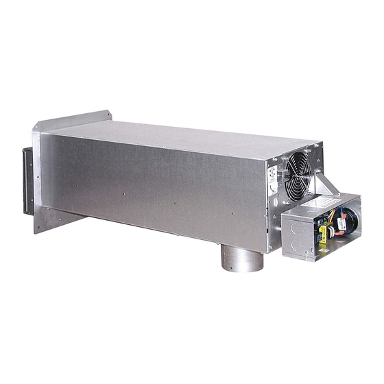
MODEL SS2
) than typical levels to maintain recommended over-fire draft
2
INCLUDES NEW UC1
UNIVERSAL CONTROL
O
F (121
O
C) AT VENT
REV. 7/02
P/N 8504105
Advertisement
Table of Contents
Troubleshooting

Related Manuals for TJERNLUND SS2 SIDESHOT WITH UC1 UNIVERSAL CONTROL (VERSION X.02) 8504105 REV 0702


Summary of Contents for TJERNLUND SS2 SIDESHOT WITH UC1 UNIVERSAL CONTROL (VERSION X.02) 8504105 REV 0702
-
Page 1: Installation Instructions
See “Oil Draft Adjustment Procedure” on page 16 of this manual or consult factory at 1-800-255-4208 with questions prior to installation. DO NOT DESTROY. PLEASE READ CAREFULLY AND KEEP IN A SAFE PLACE FOR FUTURE REFERENCE. Copyright © 2002, Tjernlund Products, Inc. All rights reserved. P/N 8504105... -
Page 2: Table Of Contents
Address all correspondence to: Customer Service • Tjernlund Products, Inc. • 1601 Ninth Street • White Bear Lake, MN 55110-6794 Call us toll free at 800-255-4208, visit our web site @ www.tjernlund.com or email us at fanmail@tjfans.com. TABLE OF CONTENTS Description and Specifications ............................1, 2... -
Page 3: Installation Restrictions
SPECIFICATIONS Motor: 115/1/60, 3000 RPM, 1/25 HP, 1.6 FLA, Ball Bearing Permanently Lubricated. Fan Proving Switch: Non-adjustable set point of -.40” W.C. on pressure drop. High Limit: Manual reset N/C contacts, open at 170 o F + 8 o F (77 o C + 5 o C). UC1 Universal Control: See UC1 Universal Control Board Features on page 4. -
Page 4: Cautions
CAUTIONS The SS2 must be installed by a qualified installer (an individual properly licensed and/or trained) in accordance with all local codes or, in their absence, in accordance with the appropriate National Fire Protection Association #31, #54, #211 and the National Electrical Code. -
Page 5: Sideshot ® With Integral Uc1 Universal Control Board Features
P1 - P2 SAFETY CIRCUIT C, GND, F AUXILIARY DEVICE TERMINALS COMMUNICATION TERMINALS 1 mA @ 5VDC. 2 mA @ 5VDC. For Tjernlund MAC1E or SEE WARNING # 1. MAC4E auxiliary devices. SEE WARNING # 1. DIP SWITCH SETTINGS Pre-Purge (1-2) -
Page 6: Pre / Post-Purge & Prover Status Check Settings
PRE / POST PURGE AND PROVER STATUS CHECK DIP SWITCH SETTINGS Remove power to SS2 and heating equipment when installing, servicing or changing dip switch settings. Failure to do so may result in personal injury and/or equipment damage. LED #5 (RED) should not be on if 115 VAC supply power is removed from the control. Pre-purge Used for a Venter with longer vent runs to get draft fully established throughout the vent system prior to burner ignition. -
Page 7: Vent Hood Termination Clearances U.s. Installations
VENT HOOD TERMINATION CLEARANCES FOR U.S. INSTALLATIONS The SS2 has been Listed according to the requirements of the National Fire Protection Association #31, #54 and #211 as follows below, (See Diagram A). • The exit terminals of mechanical draft systems shall not be less than 7 feet above grade when located adjacent to public walkways. •... -
Page 8: Installation Tools Required
A venting system shall not terminate within 1.8 m (6ft) of the following: • A window, door or mechanical air supply inlet of any building, including soffit openings • A gas service regulator vent outlet • A combustion air inlet •... - Page 9 SS2 VENT SYSTEM CLEARANCES FROM COMBUSTIBLES & OBSTRUCTIONS With an inlet flue gas temperature of 650 o F (343 o C) or below, the SS2 has been Listed for Zero Clearance from combustibles. NOTE: You must allow a minimum 2 foot distance of unobstructed clearance behind the SS2 Vent System for doing maintenance.
-
Page 10: Vent System Installation
NOTE: For easy one person installations, remove (3) screws from rear and bottom of vent cabinet. Slide venter assembly out of SS2 cabinet and set aside being careful not to damage housing. After SS2 cabinet is secured to the outside wall, and the vibration isolation mount is installed to the inside wall, replace venter assembly and all (9) screws, (See Diagram D). -
Page 11: Installation Of Vent Pipe
4. a) If installing the bracket into a wood wall, drill 2 pilot holes at each point established in step 3 with a 1/8" drill bit approximately 1" deep and install the screws provided to secure the bracket to the wall. If installing the bracket into a masonry wall, drill 2 holes at each point established in step 3 with a 1/4"... -
Page 12: Electrical Wiring
The steps listed under each diagram are intended as a supplement to the diagram. Wiring colors or designations may vary by manufacturer. If you are unable to wire the SS2 as outlined in these instructions, call Tjernlund’s Customer Service Department toll free at 1-800-255-4208 for assistance. - Page 13 SIDESHOT WITH INTEGRAL UC1 UNIVERSAL CONTROL CONNECTED TO A HONEYWELL R8184 SERIES OR EQUIVALENT PRIMARY CONTROL IMPORTANT: RED JUMPER POSITION MUST BE THE SAME BLACK AS APPLIANCE INTERLOCK VOLTAGE. ORANGE WHITE IGNITION TRANS CALL JUMPER HONEYWELL WHITE R8184 SERIES OR EQUIVALENT WHITE BLACK SUPPLY...
-
Page 14: Wiring To Oil Fired Equipment
SIDESHOT WITH INTEGRAL UC1 UNIVERSAL CONTROL CONNECTED WITH AN AQUASTAT IMPORTANT: AQUASTAT RED JUMPER POSITION MUST BE THE SAME AS APPLIANCE INTERLOCK VOLTAGE. CALL JUMPER SUPPLY LINE VOLTAGE OIL BURNER 115 VAC PRIMARY CONTROL, BURNER 50/60 Hz LEGEND: RELAY OR GAS VALVE 115 VAC D/N 9183046-7 IMPORTANT:... -
Page 15: Wiring To Gas Fired Appliance
SIDESHOT WITH INTEGRAL UC1 UNIVERSAL CONTROL CONNECTED WITH A HONEYWELL R8184 SERIES OR EQUIVALENT PRIMARY CONTROL AND A BURNER MOTOR POST-PURGE THERMOSTAT BLACK IMPORTANT: ORANGE RED JUMPER POSITION MUST BE THE SAME AS APPLIANCE INTERLOCK VOLTAGE. WHITE HONEYWELL R8184 CALL SERIES OR EQUIVALENT JUMPER OIL VALVE... - Page 16 SIDESHOT WITH INTEGRAL UC1 CONTROL CONNECTED WITH A 24 VAC ELECTRONIC IGNITION MODULE IMPORTANT: RED JUMPER POSITION MUST BE THE SAME AS APPLIANCE INTERLOCK VOLTAGE. SPARK CALL JUMPER SUPPLY 24V GND LEGEND: 115 VAC 50/60 Hz 115 VAC BNR GND 24 VAC MV / PV D/N 9183046-8...
-
Page 17: Draft Adjustment Procedure (Oil)
Do not allow heating system to run at less than a -.02” W.C. over fire draft or at a CO level that is less than a 1% reduction from the value measured at a trace of smoke and a -.02” W.C. over fire draft. If these parameters are unobtainable, contact Tjernlund at 1-800-255-4208 for Technical Assistance. -
Page 18: Draft Adjustment Procedure (Gas)
3. If a draft gauge is not available test for spillage at the draft hood, diverter or barometric draft control using the flame from a match, lighter or candle and determine the following: DIAGRAM K A. The flame or smoke is being drawn into the draft hood, diverter or barometric draft control. DRAFT ADJUSTMENT LOCKING KEPS NUT B. -
Page 19: Troubleshooting Electrical Problems
Accessory air intakes are available that connect to the burner motor, using it to pull in the outdoor air. The Tjernlund IN-FORCER Combustion Air Intake tempers the raw outdoor air as it is delivered to the burner. -
Page 20: Maintenance
Yes, LED #1 (Amber) is lit: Verify Prover safety circuit fault does not exist. See LED indicator light status & faults, on page 18. If faults exist check Prover P1 & P2 safety circuit. If no faults exist, check for 115 VAC across terminals N and MTR. Voltage present: Replace SS2 motor, p/n 950-0015 or SS2 cooling fan, p/n 950-0020. -
Page 21: How To Obtain Service
Tjernlund Products, Inc. will issue credit or provide a free part to replace one that becomes defective during the two year warranty period. Proof of date of the installation in the form of the contractor sales/installation receipt is necessary to prove the unit has been in service for under two years. - Page 22 TJERNLUND LIMITED TWO YEAR WARRANTY Tjernlund Products, Inc. warrants to the original purchaser of this product that the product will be free from defects due to faulty material or work- manship for a period of (2) years from the date of original purchase or delivery to the original purchaser, whichever is earlier. Remedies under this warranty are limited to repairing or replacing, at our option, any product which shall, within the above stated warranty period, be returned to Tjernlund Products, Inc.
Need help?
Do you have a question about the SS2 SIDESHOT WITH UC1 UNIVERSAL CONTROL (VERSION X.02) 8504105 REV 0702 and is the answer not in the manual?
Questions and answers