Table of Contents
Advertisement
INSTALLATION INSTRUCTIONS
Recognize this symbol as an indication of important Safety Information!
!
OWNER INSTRUCTIONS, DO NOT DESTROY
NOTE: FLUE GAS TEMPERATURES MUST NOT EXCEED
650
F AT VENT SYSTEM INLET.
o
THESE INSTRUCTIONS ARE INTENDED AS AN AID TO QUALIFIED, LICENSED
SERVICE PERSONNEL FOR PROPER INSTALLATION, ADJUSTMENT AND
OPERATION OF THIS UNIT. READ THESE INSTRUCTIONS THOROUGHLY
BEFORE ATTEMPTING INSTALLATION OR OPERATION. FAILURE TO FOLLOW
THESE INSTRUCTIONS MAY RESULT IN IMPROPER INSTALLATION, ADJUST-
MENT, SERVICE OR MAINTENANCE POSSIBLY RESULTING IN FIRE, ELECTRI-
CAL SHOCK, CARBON MONOXIDE POISONING, EXPLOSION, OR PERSONAL
INJURY OR PROPERTY DAMAGE.
DO NOT DESTROY. PLEASE READ CAREFULLY AND
KEEP IN A SAFE PLACE FOR FUTURE REFERENCE.
Copyright © 1999, Tjernlund Products, Inc. All rights reserved
TJERNLUND PRODUCTS, INC.
1601 Ninth Street • White Bear Lake, MN 55110-6794
PHONE (800) 255-4208 • (651) 426-2993 • FAX (651) 426-9547
Visit our web site • www.tjernlund.com
T0890551100
MODEL SS1
REV. A 11/99
P/N 8504041
Advertisement
Table of Contents

Related Manuals for TJERNLUND SS1 SIDESHOT (DISCONTINUED VERSION-PRE UC1 UNIVERSAL CONTROL) 8504041 REV A 1199


Summary of Contents for TJERNLUND SS1 SIDESHOT (DISCONTINUED VERSION-PRE UC1 UNIVERSAL CONTROL) 8504041 REV A 1199
-
Page 1: Installation Instructions
MENT, SERVICE OR MAINTENANCE POSSIBLY RESULTING IN FIRE, ELECTRI- CAL SHOCK, CARBON MONOXIDE POISONING, EXPLOSION, OR PERSONAL INJURY OR PROPERTY DAMAGE. DO NOT DESTROY. PLEASE READ CAREFULLY AND KEEP IN A SAFE PLACE FOR FUTURE REFERENCE. Copyright © 1999, Tjernlund Products, Inc. All rights reserved P/N 8504041... -
Page 2: Table Of Contents
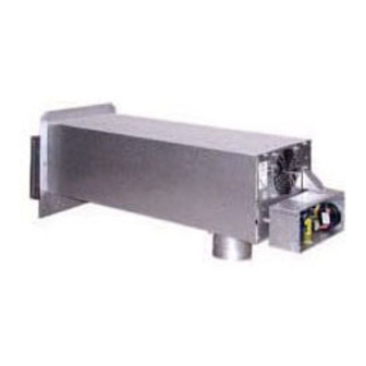
SideShot ® is a registered trademark of Tjernlund Products, Inc. for their Model SS1 Vent System. DESCRIPTION The SideShot is a mechanical vent system designed and listed for use with natural draft oil or gas heating equipment. It is factory assembled and wired. -
Page 3: Installation Restrictions
SPECIFICATIONS Motor: 115/1/60, 3300 RPM, 212 watts, 2.28 FLA Fan Proving Switch: Non-adjustable set point of -.05" W.C., Contacts rated for an inductive load of 6.2 FLA at 120 VAC. High Limit: Manual reset N/C contacts, open at 135 o F + 10 o F, Contacts rated at 10 FLA at 120 VAC. Post-Purge Timer: Adjustable from 1 to 10 minutes. -
Page 4: Cautions
CAUTIONS 1. Disconnect power supply from the SideShot and heating equipment when making wiring connections and servicing the SideShot. Failure to do so may result in personal injury and/or equipment damage. 2. Failure to install, maintain and/or operate the SideShot in accordance with manufacturer's instructions may result in conditions which can produce bodily injury and property damage. -
Page 5: Sideshot Terminology
The following steps should be followed in making the safety inspection: 1. Conduct a gas leakage test of the appliance piping and control system downstream of the shutoff valve in the supply line to the appliance. 2. Visually inspect the venting system and determine there is no blockage or restriction, leakage, corrosion and other deficiencies which could cause an unsafe condition. -
Page 6: Installation
• The venting system shall terminate at least 4 feet below, 4 feet horizontally from or 1 foot above any door, window or gravity air inlet into any building. • The bottom of the vent terminal shall be located at least 12 inches above grade. •... -
Page 7: Vent Hood Installation
DIAGRAM B 2. Using 1/2" bit, drill pilot holes noted on each side of the template from inside through rim-joist, wall board, siding, etc., keeping drill bit perpendicular to the wall. 1/2" bit must be long enough to penetrate through exterior. 3. -
Page 8: Installation Of Rain Shield
8. Slide the Vent Hood through the wall while taking care installing the rain shield as shown, (See Diagram E). The nuts located on the Vent Hood outermost casing should be facing up when sliding it through the wall. Mount Vent Hood to the exterior using four #8 x 3"... -
Page 9: Plenum Installation
NOTCH BRACING It is recommended and local codes may dictate that the joist be reinforced as outlined below. Bracing of the rim joist is not necessary. 1. Cut two 2 x 4 pieces of wood 28 inches in length. 2. Center both pieces on each side of the floor joist above the notch and drive 8 16D or larger nails into each piece, (See Diag. H) DIAGRAM H CONNECTING THE PLENUM TO THE VENT HOOD NOTES: Cut any nails which are protruding downward from the subfloor that may come in contact with the SideShot. -
Page 10: Installation Of Vent Pipe
If installing the bracket into a masonry wall, drill 2 holes at each point established in step 3 with a 1/4" masonry drill bit approximately 1" deep. Tap the masonry anchors into the holes drilled in step 4. Screw the wall bracket onto the wall. 5. - Page 11 4. Using a tube cutter, cut the sensing tube 2" from the elbow directed at the vent pipe inlet collar, (See Diagram L). Discard the cut off section of metal tube. 5. Attach the vent pipe inlet collar to the rear inlet port making sure that the sensing tube is orientated as shown, (See Diagram M). NOTE: Alignment marks on the inlet collar and plenum casing must match.
-
Page 12: Electrical Wiring
ELECTRICAL WIRING OIL All wiring from the SideShot to the appliance must be appropriate Class 1 wiring as follows: installed in rigid metal conduit, inter- mediate metal conduit, rigid non-metallic conduit, electrical metallic tubing, Type MI Cable, Type MC Cable, or be otherwise suitably protected from physical damage. - Page 13 SIDESHOT CONNECTED TO AN R8184G WITH THE APPLIANCE BURNER MOTOR LESS THAN 6.2 AMPS @ 120 VAC LADDER DIAGRAM CONNECTION DIAGRAM NOTES: When interlocking the SideShot with the primary control of the appliance, wire all other furnace/boiler controls as normally done when conventional venting before continuing. Disconnect power from the appliance before attempting to interlock the SideShot.
-
Page 14: Wiring To Oil Fired Appliance
SIDESHOT CONNECTED TO 24 VAC THERMOSTAT CIRCUIT WITH BURNER MOTOR POST PURGE (P/N 950-2043) (USE IN CONJUNCTION WITH DIAGRAM ON BOTTOM OF PAGE 12) SIDESHOT CONNECTED TO A RIELLO BURNER SIDESHOT CONNECTED TO A CARLIN CONTROL... -
Page 15: Wiring To Gas Fired Appliance
SIDESHOT WIRED WITH WEIL-MCLAIN WGO, WTGO AND SGO-W WATER BOILERS OR AQUASTAT CONTROLLED BURNERS WITH CARLIN 602002 PRIMARY CONTROL ELECTRICAL WIRING GAS All wiring from the SideShot to the appliance must be appropriate Class 1 wiring as follows: installed in rigid metal conduit, inter- mediate metal conduit, rigid non-metallic conduit, electrical metallic tubing, Type MI Cable, Type MC Cable, or be otherwise suit- ably protected from physical damage. - Page 16 SIDESHOT CONNECTED TO A 24V FURNACE OR BOILER WITH INTERMITTENT IGNITION CONNECTION DIAGRAM LADDER DIAGRAM SIDESHOT CONNECTED TO A 24V BOILER WITH A STANDING PILOT LADDER DIAGRAM CONNECTION DIAGRAM NOTES: The SideShot is always interlocked with the gas valve of the appliance. Wire all other furnace/boiler controls as normally done when conventional venting before continuing.
-
Page 17: Draft Adjustment
DRAFT ADJUSTMENT OIL The SideShot Vent system will properly vent a wide range of BTU/hr. input capacities. To compensate for different burner capaci- ties, vent connector lengths and wind conditions it features a draft adjustment located on the outside of the Vent Hood. In general, positioning the draft adjustment inward will cause the SideShot to operate at lowest capacity. -
Page 18: Combustion Air
NOTES: All draft adjustments are approximate. This chart is to be used for initial draft adjustment only. Subsequent draft adjustments may be required to com- pensate for various field conditions: wind, vent pipe resistance, building pressure, multiple appliances, etc. BTU/HR input ratings assume 30% or less excess air for flame retention burners and 50% to 100% excess air for conventional oil burners. -
Page 19: Troubleshooting Oil Odors
Accessory air intakes are available that connect to the burner motor, using it to pull in the outdoor air. The Tjernlund IN-FORCER Combustion Air Intake tempers the raw outdoor air as it is delivered to the burner. - Page 20 SYMPTOM 1: SIDESHOT MOTOR RUNS CONTINUOUSLY Remove the external control wire attached to terminal "O" of the SideShot terminal strip. This should cause Replace Timer/Relay, the motor to shut down within ten minutes (after the post-purge cycle has finished). Part #950-1067. SideShot and appliance are not interlocked correctly.
- Page 21 SYMPTOM 3: SIDESHOT MOTOR WILL NOT OPERATE Step 1. Check circuit breaker or fuse Verify that 115V is present between "L1" and "L2" and electrical connections. on terminal strip, (See Diagram M). SideShot and appliance are not interlocked correctly Step 2. or malfunction of appliance controls.
-
Page 22: Maintenance
MAINTENANCE DIAGRAM N WHEEL INSPECTION (DIAGRAM N) 1. The SideShot blower wheel must be inspected annually. Particulates, such as soot, oil impurities and sheet rock dust, can prevent proper venting and will cause noise and vibration. Follow instructions, below for motor/wheel assembly removal. 2. -
Page 23: Warranty
Tjernlund Products, Inc. will issue credit or provide a free part to replace one that becomes defective during the two year warranty period. If the part is over 30 months old, proof of date of the installation in the form of the contractor sales/installation receipt is necessary to prove the unit has been in service for under two years.
Need help?
Do you have a question about the SS1 SIDESHOT (DISCONTINUED VERSION-PRE UC1 UNIVERSAL CONTROL) 8504041 REV A 1199 and is the answer not in the manual?
Questions and answers