Table of Contents
Advertisement
INSTALLATION INSTRUCTIONS
Recognize this symbol as an indication of important Safety Information!
!
OWNER INSTRUCTIONS, DO NOT DESTROY
NOTE: FLUE GAS TEMPERATURES MUST NOT EXCEED
o
650
F AT VENT SYSTEM INLET.
THESE INSTRUCTIONS ARE INTENDED AS AN AID TO QUALIFIED, LICENSED
SERVICE PERSONNEL FOR PROPER INSTALLATION, ADJUSTMENT AND
OPERATION OF THIS UNIT. READ THESE INSTRUCTIONS THOROUGHLY
BEFORE ATTEMPTING INSTALLATION OR OPERATION. FAILURE TO FOLLOW
THESE INSTRUCTIONS MAY RESULT IN IMPROPER INSTALLATION, ADJUST-
MENT, SERVICE OR MAINTENANCE POSSIBLY RESULTING IN FIRE, ELECTRI-
CAL SHOCK, CARBON MONOXIDE POISONING, EXPLOSION, OR PERSONAL
INJURY OR PROPERTY DAMAGE.
DO NOT DESTROY. PLEASE READ CAREFULLY AND
KEEP IN A SAFE PLACE FOR FUTURE REFERENCE.
Copyright © 2002, Tjernlund Products, Inc. All rights reserved
TJERNLUND PRODUCTS, INC.
1601 Ninth Street • White Bear Lake, MN 55110-6794
PHONE (800) 255-4208 • (651) 426-2993 • FAX (651) 426-9547
Visit our web site • www.tjernlund.com
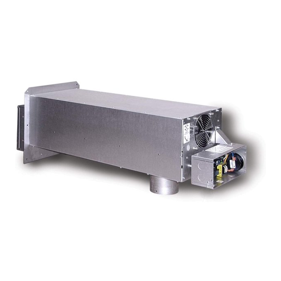
MODEL SS1
INCLUDES NEW UC1
UNIVERSAL CONTROL
REV. 7/02
P/N 8504102
Advertisement
Table of Contents
Troubleshooting

Related Manuals for TJERNLUND SS1 SIDESHOT WITH UC1 UNIVERSAL CONTROL (VERSION X.02) 8504102 REV 0702


Summary of Contents for TJERNLUND SS1 SIDESHOT WITH UC1 UNIVERSAL CONTROL (VERSION X.02) 8504102 REV 0702
-
Page 1: Installation Instructions
MENT, SERVICE OR MAINTENANCE POSSIBLY RESULTING IN FIRE, ELECTRI- CAL SHOCK, CARBON MONOXIDE POISONING, EXPLOSION, OR PERSONAL INJURY OR PROPERTY DAMAGE. DO NOT DESTROY. PLEASE READ CAREFULLY AND KEEP IN A SAFE PLACE FOR FUTURE REFERENCE. Copyright © 2002, Tjernlund Products, Inc. All rights reserved P/N 8504102... -
Page 2: Table Of Contents
Tjernlund Products welcomes your comments and questions. Address all correspondence to: Customer Service • Tjernlund Products, Inc. • 1601 Ninth Street • White Bear Lake, MN 55110-6794 Call us toll free at 800-255-4208, visit our web site @ www.tjernlund.com or email us at fanmail@tjfans.com. TABLE OF CONTENTS Page (s) Description and Specifications ............................1, 2... -
Page 3: Installation Restrictions
SPECIFICATIONS Motor: 115/1/60, 3300 RPM, 212 watts, 2.28 FLA Fan Proving Switch: Non-adjustable, N/O with a set point of -.04" W.C. High Limit: Manual reset, N/C contacts, open at 79 o C (175 o F) + 8 o C (15 o F) UC1 Universal Control: See UC1 Universal Control Board Features on page 4. -
Page 4: Cautions
CAUTIONS The SS1 must be installed by a qualified installer (an individual properly licensed and/or trained) in accordance with all local codes or, in their absence, in accordance with the appropriate National Fire Protection Association #31, #54, #211 and the National Electrical Code. -
Page 5: Sideshot ® With Integral Uc1 Universal Control Board Features
P1 - P2 SAFETY CIRCUIT C, GND, F AUXILIARY DEVICE TERMINALS COMMUNICATION TERMINALS 1 mA @ 5VDC. 2 mA @ 5VDC. For Tjernlund MAC1E or SEE WARNING # 1. MAC4E auxiliary devices. SEE WARNING # 1. DIP SWITCH SETTINGS Pre-Purge (1-2) -
Page 6: Pre / Post-Purge & Prover Status Check Settings
PRE / POST PURGE AND PROVER STATUS CHECK DIP SWITCH SETTINGS Remove power to SS1 and heating equipment when installing, servicing or changing dip switch settings. Failure to do so may result in personal injury and/or equipment damage. LED #5 (RED) should not be on if 115 VAC supply power is removed from the control. Pre-purge Used for a Venter with longer vent runs to get draft fully established throughout the vent system prior to burner ignition. -
Page 7: Termination Clearances
PLENUM AND VENT HOOD CLEARANCE FROM COMBUSTIBLES With an inlet flue gas temperature of 650 o F or below, the SideShot has been Listed for the following clearances from combustible materials: IMPORTANT Vent Hood and top of Plenum: Zero Clearance Plenum front and sides: 1/2 inch Plenum rear: 3 inches VENT HOOD TERMINATION CLEARANCES... -
Page 8: Installation
INSTALLATION Tools required: • Reciprocating Saw • 1/2", 7/16",5/8" Wrench • Drill and 1/8", 1/4", 1/2" Bits • 1/4" Masonry Drill Bit • Blade Screwdriver • 1/4", 5/16”, 11/32" Nut Runner or Socket • Wire Cutter/Stripper • Hammer • Tube Cutter INSTALLING VENT HOOD TERMINUS 1. -
Page 9: Vent Hood Installation
DIAGRAM D DIAGRAM E NOTE: For mounting on vinyl or lap siding a wood frame with 1” x 1 1/2” on the sides and top and 1” x 2” material on bottom can be utilized on exterior wall. This will provide a flush mounting surface for the hood and a nicely finished look with “J”... -
Page 10: Plenum Installation
NOTCH BRACING It is recommended and local codes may dictate that the joist be reinforced as outlined below. Bracing of the rim joist is not necessary. 1. Cut two 2 x 4 pieces of wood 28 inches in length. 2. Center both pieces on each side of the floor joist above the notch and drive 8 16D or larger nails into each piece, (See Diag. H) DIAGRAM H CONNECTING THE PLENUM TO THE VENT HOOD NOTE: Cut any nails which are protruding downward from the subfloor that may come in contact with the SideShot. -
Page 11: Installation Of Vent Pipe
DIAGRAM J IMPORTANT: Adjust SS1 mounting bracket for a slight downward pitch towards exit terminal. INSTALLATION OF VENT PIPE If installing the SideShot Vent System on an oil or gas appliance which is not equipped with a draft hood or draft diverter, a baro- metric draft control must be used. - Page 12 4. Using a tube cutter, cut the sensing tube 2" from the elbow directed at the vent pipe inlet collar, (See Diagram L). Discard the cut off section of metal tube. 5. Attach the vent pipe inlet collar to the rear inlet port making sure that the sensing tube is orientated as shown, (See Diagram M). NOTE: Alignment marks on the inlet collar and plenum casing must match.
-
Page 13: Electrical Wiring
The steps listed under each diagram are intended as a supplement to the diagram. Wiring colors or designations may vary by manufacturer. If you are unable to wire the SS1 as outlined in these instructions, call Tjernlund’s Customer Service Department toll free at 1-800-255-4208 for assistance. - Page 14 SIDESHOT WITH INTEGRAL UC1 UNIVERSAL CONTROL CONNECTED TO A HONEYWELL R8184 SERIES OR EQUIVALENT PRIMARY CONTROL IMPORTANT: RED JUMPER POSITION MUST BE THE SAME BLACK AS APPLIANCE INTERLOCK VOLTAGE. ORANGE WHITE IGNITION TRANS CALL JUMPER HONEYWELL WHITE R8184 SERIES OR EQUIVALENT WHITE BLACK SUPPLY...
-
Page 15: Wiring To Oil Fired Equipment
SIDESHOT WITH INTEGRAL UC1 UNIVERSAL CONTROL CONNECTED WITH AN AQUASTAT IMPORTANT: LEGEND: RED JUMPER POSITION MUST BE THE SAME 115 VAC AS APPLIANCE INTERLOCK VOLTAGE. AQUASTAT D/N 9183046-7 CALL JUMPER SUPPLY LINE VOLTAGE OIL BURNER 115 VAC PRIMARY CONTROL, BURNER 50/60 Hz RELAY OR GAS VALVE GROUND... - Page 16 SIDESHOT WITH INTEGRAL UC1 UNIVERSAL CONTROL CONNECTED WITH A HONEYWELL R8184 SERIES OR EQUIVALENT PRIMARY CONTROL AND A BURNER MOTOR POST-PURGE THERMOSTAT BLACK IMPORTANT: ORANGE RED JUMPER POSITION MUST BE THE SAME AS APPLIANCE INTERLOCK VOLTAGE. WHITE HONEYWELL R8184 CALL SERIES OR EQUIVALENT JUMPER OIL VALVE...
-
Page 17: Wiring To Gas Fired Appliance
SIDESHOT WITH INTEGRAL UC1 CONTROL CONNECTED WITH A 24 VAC ELECTRONIC IGNITION MODULE IMPORTANT: RED JUMPER POSITION MUST BE THE SAME AS APPLIANCE INTERLOCK VOLTAGE. SPARK CALL JUMPER SUPPLY 24V GND 115 VAC 50/60 Hz BNR GND GROUND MV / PV IMPORTANT: LEGEND: CRIMP GROUND WIRE TO GROUNDING... -
Page 18: Draft Adjustment Procedure (Oil)
DRAFT ADJUSTMENT PROCEDURE NOTES: All draft adjustments are approximate. This chart is to be used for initial draft adjustment only. Subsequent draft adjustments may be required to com- pensate for various field conditions: wind, vent pipe resistance, building pressure, multiple appliances, etc. BTU/HR input ratings assume 30% or less excess air for flame retention burners and 50% to 100% excess air for conventional oil burners. -
Page 19: Draft Adjustment Procedure (Gas)
Do not allow heating system to run at less than a -.02” W.C. over fire draft or at a CO level that is less than a 1% reduction from the value measured at a trace of smoke and a -.02” W.C. over fire draft. If these parameters are unobtainable, contact Tjernlund at 1-800-255-4208 for Technical Assistance. -
Page 20: Combustion Air
C. If the heater has a two stage or modulating gas valve verify that burner operates properly at both low and high fire. If the draft appears excessive adjust SS1 Vent Hood cone in (less draft) or adjust barometric for (less draft) repeat steps A through C. -
Page 21: Troubleshooting Electrical Problems
Accessory air intakes are available that connect to the burner motor, using it to pull in the outdoor air. The Tjernlund IN-FORCER Combustion Air Intake tempers the raw outdoor air as it is delivered to the burner. -
Page 22: Maintenance
Yes, LED #1 (Amber) is lit: Verify Prover safety circuit fault does not exist. See LED indicator light status & faults, on page 20. If faults exist check Prover P1 & P2 safety circuit. If no faults exist, check for 115 VAC across terminals N and MTR. Voltage present: Replace SS1 motor part number 950-0625. -
Page 23: Removal & Replacement Of Motor/Wheel
If you have any questions about your Power Venter or if it requires adjustment, repair or routine maintenance, we suggest that you contact your installer, contractor or service agency. If you require technical information contact Tjernlund Products, Inc. at 1-800-255-4208. When contacting Tjernlund Products, Inc., please have the following information available: Model of the Power Venter as shown on the label attached to Power Venter. - Page 24 Tjernlund Products, Inc. will issue credit or provide a free part to replace one that becomes defective during the two year warranty period. Proof of date of the installation in the form of the contractor sales/installation receipt is necessary to prove the unit has been in service for under two years.
-
Page 26: Template A Vent Hood Terminus
BACKSIDE OF TEMPLATE B...
Need help?
Do you have a question about the SS1 SIDESHOT WITH UC1 UNIVERSAL CONTROL (VERSION X.02) 8504102 REV 0702 and is the answer not in the manual?
Questions and answers
Replaced motor & wheel, pressure switch & have a clear vacuum tube to the switch. The pressure sw will not make. Don't believe that there are any blockages have exhaust cone out
The pressure switch on the TJERNLUND SS1 Sideshot with UC1 Universal Control may not be activating after replacing the motor, wheel, and pressure switch due to several possible causes:
1. Incorrect Wiring – Ensure that all motor and pressure switch connections are correctly wired according to the wiring diagram. Verify that the red jumper on the UC1 control board is in the correct position based on the appliance interlock voltage.
2. Improper Motor Installation – If the motor is not properly seated or secured, it may not generate the required airflow to activate the pressure switch.
3. Blocked or Restricted Venting – Check for any obstructions or restrictions in the venting system that could prevent proper air movement.
4. Faulty Pressure Switch or Tubing – Verify that the pressure switch tubing is correctly connected and not kinked, blocked, or leaking.
5. Dip Switch Settings on UC1 Board – Ensure that the dip switch settings for the prover status check and pre/post-purge settings are correctly configured.
6. Insufficient Power Supply – Confirm that the system is receiving the correct voltage (115V or 24V) and that the red voltage jumper is in the correct location.
7. Faulty Control Board – If all other factors check out, the UC1 Universal Control board may be malfunctioning and require further testing or replacement.
Checking these factors should help identify the issue preventing the pressure switch from activating.
This answer is automatically generated