Table of Contents
Advertisement
Quick Links
IMPORTANT!!! UC1 BOARD VERSION X.06 UPDATES
IMPORTANT: This upgraded circuit board features:
A new #6 power LED
Constant red when 115 VAC is supplied to L & N.
A new color for the #2 LED
Constant blue when fan prover safety circuit is closed.
A revised #5 LED
With no call for heat present, flashes 3 seconds on /
3 seconds off if microcontroller is working properly.
IMPORTANT:
For 950-8804 UC1 Replacement Board Kits: If this is a 950-8804 UC1 board kit and you are replacing an existing UC1 board with this
new board, note Dip Switch settings on existing UC1 circuit board so that those same settings can be positioned on this replacement circuit
board. NOTE: Adhere appropriate included label over existing label in UC1 or SideShot electrical box. Also adhere "Checking Memory for
Last Fault Code" sticker on inside of UC1 or SideShot SS1 Series electrical box. On SS2 Series adhere to underside of electrical box.
For SideShot Series SS1 Models: The Pre-Cycle Prover Status Check is deactivated from the factory on the SS1 Series. Because of the
low set point of the SS1 Fan Prover (as low as .03" w.c.) cross winds may cause the Fan Prover to close prior to a call for heat. Activating the
Prover Status Check on the SS1 may cause nuisance lockouts. Important: Deactivate the Pre-Cycle Prover status check if installing this board
on a new or existing SS1 installation by pushing the #9 dip switch up or "ON" to disable.
For Draft Inducers with the UC1: Natural draft or winds may be sufficient to close the fan prover switch contacts prior to a call for heat
when using the PS1505 fan prover with a draft inducer. Keeping the Pre-Cycle Prover Status Check activated may cause nuisance lockouts.
Important: Deactivate the Pre-Cycle Prover status check if installing this board on a new or existing draft inducer installation by pushing the #9
dip switch up or "ON" to disable.
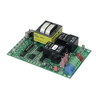
LED INDICATOR LIGHTS
LED #1 (Amber) Appliance call for heat.
LED #2 (Blue)
Safety circuit through P1 & P2 (Venter Fan Prover and/or High Limit). Indicates Venter prover is closed during run cycle.
Burner circuit is energized with Interlock Relay contact closure from terminal 3 to 4.
LED #3 (Green) Power switched to Venter motor from L to MTR & M.
LED #4 (Red)
Status / Fault indicator.
LED #5 (Red)
Used as a status indicator.
LED #6 (Red)
115 VAC power supplied to board.
P/N: 8505017
TJERNLUND PRODUCTS, INC.
1601 Ninth Street • White Bear Lake, MN 55110-6794
PHONE (800) 255-4208 • (651) 426-2993 • FAX (651) 426-9547
Visit our web site • www.tjernlund.com
NEW X.06 VERSION UC1 BOARD FEATURES
New LED # 6 RED
115V power supplied
to UC1 L & N terminals
LED # 2 now BLUE
(previously GREEN)
LED # 5 RED With no
call for heat, flashes 3
seconds on / 3 seconds
off if microcontroller is
working properly.
©2005 TJERNLUND PRODUCTS, INC. ALL RIGHTS RESERVED
P1 P2
C GND F
LED 6 (RED) POWER LED
(1
9)
LED 1 (AMBER)
LED 2 (BLUE)
LED 3 (GREEN)
LED 4 (RED)
LED 5 (RED)
DRY
APPLIANCE
VENTER
INTERLOCK
MOTOR
RELAY
RELAY
24 V
115 V
J1
J2
XL
XN
N
M
A B 1 2 3 4 L N
REV. B 07/05
MTR
Advertisement
Table of Contents
Troubleshooting

Related Manuals for TJERNLUND SS2 SIDESHOT WITH UC1 UNIVERSAL CONTROL (VERSION X.06) 8504105 REV C 0705


Summary of Contents for TJERNLUND SS2 SIDESHOT WITH UC1 UNIVERSAL CONTROL (VERSION X.06) 8504105 REV C 0705
- Page 1 LED #3 (Green) Power switched to Venter motor from L to MTR & M. LED #4 (Red) Status / Fault indicator. LED #5 (Red) Used as a status indicator. LED #6 (Red) 115 VAC power supplied to board. P/N: 8505017 ©2005 TJERNLUND PRODUCTS, INC. ALL RIGHTS RESERVED REV. B 07/05...
- Page 2 LED STATUS INDICATORS LED #4 & #5 (Red) Flashing Alternately = Venter in Pre-purge. (Pre-Purge options 0, 5, 20, 35 seconds) LED #4 & #5 (Red) Flashing in Unison = Venter in Post-Purge. (Post-Purge options 0, 30 seconds or 1, 2, 4, 8, 16 minutes) LED #4 Flashes Continuously* = Fan Prover opened for more than 10 seconds during burner cycle.
-
Page 3: Installation Instructions
See “Oil Draft Adjustment Procedure” on page 15 of this manual or consult factory at 1-800-255-4208 with questions prior to installation. DO NOT DESTROY. PLEASE READ CAREFULLY AND KEEP IN A SAFE PLACE FOR FUTURE REFERENCE. Copyright © 2005, Tjernlund Products, Inc. All rights reserved. P/N 8504105... -
Page 4: Table Of Contents
Oil burner capacities exceeding 1 GPH may require the burner to be adjusted to more efficient (12.5-13% CO 2 ) than typical levels to maintain recommended over-fire draft settings. See “Oil Draft Adjustment Procedure” on page 15 of this manual or consult Tjernlund at 1-800-255-4208... -
Page 5: Installation Restrictions
SPECIFICATIONS Motor: 115/1/60, 3000 RPM, 1/25 HP, 1.6 FLA, Ball Bearing Permanently Lubricated. Fan Proving Switch: Non-adjustable set point of -.40” W.C. on pressure drop. High Limit: Manual reset N/C contacts, open at 170 o F + 8 o F (77 o C + 5 o C). UC1 Universal Control: See UC1 Universal Control Board Features on page 4. -
Page 6: Cautions
CAUTIONS The SS2 must be installed by a qualified installer (an individual properly licensed and/or trained) in accordance with all local codes or, in their absence, in accordance with the appropriate National Fire Protection Association #31, #54, #211 and the National Electrical Code. In the absence of local codes in Canada, installations must comply with CSA Std 139 (The National Building Code of Canada) and CSA Std 22.1 (The Canadian Electrical Code). -
Page 7: Sideshot ® With Integral Uc1 Universal Control Board Features
P1 - P2 SAFETY CIRCUIT C, GND, F AUXILIARY DEVICE TERMINALS COMMUNICATION TERMINALS 1 mA @ 5VDC. 2 mA @ 5VDC. For Tjernlund MAC1E or SEE WARNING # 1. MAC4E auxiliary devices. SEE WARNING # 1. DIP SWITCH SETTINGS Pre-Purge (1-2) -
Page 8: Pre / Post-Purge & Prover Status Check Settings
LED FAULT INDICATORS Fault conditions are indicated by counting the number of times LED #4 (Red) flashes. LED #4 Flashes 2 Times Fan Prover was in electrically closed position prior to venter operation. LED #4 Flashes 3 Times* Fan Prover does not close within 60 seconds after call for heat. LED #4 Flashes 4 Times* Fan Prover did not re-close after 10 minutes of Venter operation. -
Page 9: Vent Hood Termination Clearances U.s. Installations
VENT HOOD TERMINATION CLEARANCES FOR U.S. INSTALLATIONS The SS2 has been Listed according to the requirements of the National Fire Protection Association #31, #54 and #211 as follows below, (See Diagram A). • The exit terminals of mechanical draft systems shall not be less than 7 feet above grade when located adjacent to public walkways. •... -
Page 10: Installation Tools Required
A venting system shall not terminate within .3m (1ft) of the following: • Above grade level or any surface that may support snow, ice, or debris CAUTION: The owner of the SS2 must keep the area around the vent terminal free of snow, ice and debris. If possible, do not terminate the SS2 on a wall that faces the direction of the prevailing winds. -
Page 11: Vent System Installation
INSTALLING SS2 VENT CABINET 1. a) Fold SS2 Vent Cabinet template (Inserted) along dashed line and attach between the DIAGRAM B floor joists ensuring that it is snug against the sill plate and centered between the floor joists. Follow same procedure if floor trusses are used, (See Diagram B). b) If the SS2 is not being installed between floor joists, attach the template to the wall it will be Rough-In exiting ensuring it is level. -
Page 12: Installation Of Vent Pipe
INSTALLATION OF WALL SUPPORT BRACKET 1. To prevent damage to the SS2, temporarily support the bottom of the SS2 cabinet (prop on ladder top) while assembling the wall support bracket. Assemble the wall support bracket as shown, (See Diagram H). 2. -
Page 13: Electrical Wiring
The steps listed under each diagram are intended as a supplement to the diagram. Wiring colors or designations may vary by manufacturer. If you are unable to wire the SS2 as outlined in these instructions, call Tjernlund’s Customer Service Department toll free at 1-800-255-4208 for assistance. - Page 14 SIDESHOT WITH INTEGRAL UC1 UNIVERSAL CONTROL CONNECTED TO A HONEYWELL R8184 SERIES OR EQUIVALENT PRIMARY CONTROL CONNECT TO L1 OR B1 IMPORTANT: RED JUMPER POSITION MUST BE THE SAME BLACK AS APPLIANCE INTERLOCK VOLTAGE. ORANGE WHITE CALL IGNITION TRANS JUMPER HONEYWELL WHITE R8184 SERIES...
- Page 15 SIDESHOT WITH INTEGRAL UC1 UNIVERSAL CONTROL CONNECTED WITH AN AQUASTAT IMPORTANT: RED JUMPER POSITION MUST BE THE SAME AQUASTAT AS APPLIANCE INTERLOCK VOLTAGE. CALL JUMPER SUPPLY LINE VOLTAGE OIL BURNER 115 VAC PRIMARY CONTROL, BURNER 50/60 Hz LEGEND: RELAY OR GAS VALVE 115 VAC D/N 9183046-7 IMPORTANT:...
- Page 16 SIDESHOT WITH INTEGRAL UC1 UNIVERSAL CONTROL CONNECTED TO AN OIL-FIRED FURNACE WITH A HONEYWELL T87 OR EQUIVALENT NON-POWERED THERMOSTAT IMPORTANT: RED JUMPER POSITION MUST BE THE SAME AS APPLIANCE INTERLOCK VOLTAGE. HONEYWELL T87 OR EQUIVALENT NON-POWERED THERMOSTAT IMPORTANT: REMOVE JUMPER TO AVOID BACKFEEDS OR SHORT CIRCUITS.
-
Page 17: Wiring To Gas Fired Appliance
SIDESHOT WITH INTEGRAL UC1 UNIVERSAL CONTROL CONNECTED WITH A SINGLE ZONE 24 VAC THERMOSTAT IMPORTANT: RED JUMPER POSITION MUST BE THE SAME AS APPLIANCE INTERLOCK VOLTAGE. THERMOSTAT CALL JUMPER SUPPLY INTERNAL CONTROL LEGEND: 115 VAC OF FURNACE 50/60 Hz 115 VAC 24 VAC D/N 9183046-5 IMPORTANT:... - Page 18 Do not allow heating system to run at less than a -.02” W.C. over fire draft or at a CO2 level that is less than a 1% reduction from the value measured at a trace of smoke and a -.02” W.C. over fire draft. If these parameters are unobtainable, contact Tjernlund at 1-800-255-4208 for Technical Assistance.
-
Page 19: Draft Adjustment Procedure (Oil)
9. At 5 minutes into the restart, read and record the inlet temperature ________F, ________C. If this temperature is above 250 F (121 C)., continue to step 10. If this temperature is below 250 F (121 C), insulate the pipe with an approved pipe insulation. Verify that the over fire draft and CO2 have not changed, If they have, redo the adjustment steps. -
Page 20: Troubleshooting Electrical Problems
For extreme cases of oil odor nuisance Tjernlund recommends the practice of post-purging the burner during the vent system post-purge. A burner post- purge cycle can eliminate any shortcomings of compatibility between the specific installation and the SS2. -
Page 21: Maintenance
SYMPTOM 1: SS2 OPERATES CONTINUOUSLY Verify that Venter is not in post-purge mode which could last up to 16 minutes. A factory post-purge has been set for 2 minutes. LED #4 & #5 (Red) will flash in unison during post-purge. A Venter pre-purge could also be set for up to 35 seconds. LED #4 & #5 (Red) will flash alternately during pre- purge. -
Page 22: How To Obtain Service
This warranty DOES NOT cover the complete SS2 if it is operative, except for the defective part. Tjernlund Products, Inc. will issue credit or provide a free part to replace one that becomes defective during the two year warranty period. Proof of date of the installation in the form of the contractor sales/installation receipt is necessary to prove the unit has been in service for under two years.
Need help?
Do you have a question about the SS2 SIDESHOT WITH UC1 UNIVERSAL CONTROL (VERSION X.06) 8504105 REV C 0705 and is the answer not in the manual?
Questions and answers