Table of Contents
Advertisement
Quick Links
INSTALLATION INSTRUCTIONS FOR OPTIMA
SLIMLINE BEDPAN WASHER WITH EXPOSED ROYAL
Sloanl BPW-1100
Sloan Valve Company warrants its ES-S Sensor Activated Sloan
service for which they are intended in a thoroughly reliable and efficient manner when properly installed and serviced, for a period of three years (1 year for special finishes) from date of purchase. During this period,
Sloan Valve Company will, at its option, repair or replace any part or parts which prove to be thus defective if returned to Sloan Valve Company, at customer's cost, and this shall be the sole remedy available under
this warranty. No claims will be allowed for labor, transportation or other incidental costs. This warranty extends only to persons or organizations who purchase Sloan Valve Company's products directly from Sloan
Valve Company for purpose of resale.
THERE ARE NO WARRANTIES WHICH EXTEND BEYOND THE DESCRIPTION ON THE FACE HEREOF. IN NO EVENT IS SLOAN VALVE COMPANY RESPONSIBLE FOR ANY CONSEQUENTIAL DAMAGES OF ANY MEASURE WHATSOEVER.
VALVE ROUGH-IN
BPW-1000 ESS
1-1/2"
2-1/4" MIN.
2-3/4"
(38 mm)
(57mm)
(70 mm)
34-3/8"
OVERRIDE
(873 mm)
BUTTON
17"
(425 mm)
9-1/2"
(241 mm)
TOP OF
CENTER LINE
FIXTURE
OF WASTE
FIN.
FLOOR
FIN.
WALL
BPW-1155 ESS
1-1/2"
3-3/4" MIN.
2-3/4"
(38 mm)
(95 mm)
(70 mm)
OVERRIDE
BUTTON
GRAB BAR
(NOT SUPPLIED
26-1/2"
BY SLOAN)
(673 mm)
1-1/2"
(38 mm)
17" †
(425 mm)
9-1/2"
(241 mm)
TOP OF
CENTER LINE
FIXTURE
OF WASTE
FIN.
FLOOR
FIN.
WALL
Royal BPW-1150
Regal BPW-1155
and Regal
Bedpan Washer to be made of first class materials, free from defects of material or workmanship under normal use and to perform the
®
®
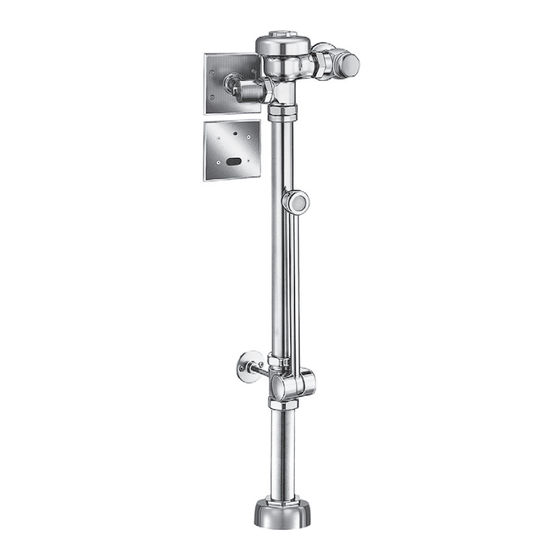
BPW-1100 ESS
4-3/4"
(121 mm)
2-1/4" MIN.
1" I.P .S.
(57 mm)
SUPPLY
(DN 25 mm)
13-3/4"
(349 mm)
26-1/2"
(673 mm)
9-1/2"
(241 mm)
TOP OF
CENTER LINE
FIXTURE
OF WASTE
FIN.
WALL
FLUSH VOLUME
4-3/4"
(121 mm)
BPW VALVE CAN BE PROVIDED WITH THE FOLLOWING FLUSHING
VOLUMES:
1" I.P .S.
SUPPLY
• Standard — Water Saver, 3.5 gpf (13.2 Lpf)
(DN 25 mm)
• "-1.6" — Low Consumption, 1.6 gpf (6.0 Lpf)
10-3/16"
(259 mm)
• "-2.4" — 2.4 gpf (9.0 Lpf)
• "-1.28" — High Efficiency 1.28 gpf (4.8 Lpf)
‡ POSITION OF SENSOR BOX CAN BE RAISED OR LOWERED
1" (25 mm) IF IN CONFLICT WITH HANDICAP GRAB BARS.
SYSTEMS SENSOR ACTIVATED
®
SLOAN
®
Royal BPW-1100
LIMITED WARRANTY
1-1/2"
2-3/4"
4-3/4"
(38 mm)
(70 mm)
(121 mm)
1" I.P .S.
SUPPLY
(DN 25 mm)
13-3/4"
OVERRIDE
(349 mm)
BUTTON
17"
(425 mm)
FIN.
FLOOR
Code No. 0816730 Rev. 1
AND REGAL
FLUSHOMETER
®
®
Slimline
Bedpan Washers
®
BPW-1000 Standard
Slimline
Bedpan Washers for ADA Installations
®
BPW-1100 Standard
BPW-1150 With Grab Bar Offset
BPW-1155 With Grab Bar Offset & Deoseptic Unit
Slimline
Bedpan Washers — Diverter Assemblies
®
DV-100 Standard
DV-105 With Deoseptic Unit
DV-110 For ADA Installation
DV-115 For ADA Installation With Deoseptic Unit
DV-120 With Grab Bar Offset
DV-125 With Grab Bar Offset & Deoseptic Unit
DV-130 Replacement Model
DV-135 Replacement Model With Deoseptic Unit
BPW-1150 ESS
1-1/2"
3-3/4" MIN.
2-3/4"
(38 mm)
(95 mm)
(70 mm)
OVERRIDE
BUTTON
GRAB BAR
(NOT SUPPLIED
26-1/2"
BY SLOAN)
(673 mm)
1-1/2"
17" †
(38 mm)
(425 mm)
9-1/2"
(241 mm)
TOP OF
CENTER LINE
FIXTURE
OF WASTE
FIN.
FLOOR
FIN.
WALL
SENSOR LOCATION & POSITIONING IS
CRITICAL!
Failure to properly position the electrical boxes to the
plumbing rough-in will result in improper installation
and impair product performance. All tradesmen
(plumbers, electricians, tile setters, etc.) involved with
the installation of this product must coordinate their
work to assure proper product installation.
(08/20)
4-3/4"
(121 mm)
1" I.P .S.
SUPPLY
(DN 25 mm)
10-3/16"
(259 mm)
Advertisement
Table of Contents

Related Manuals for Sloan Royal BPW-1150


Summarization of Contents
Valve Rough-in Diagrams
BPW-1000 ESS Rough-in
Diagram showing rough-in dimensions for BPW-1000 ESS valve.
BPW-1100 ESS Rough-in
Diagram showing rough-in dimensions for BPW-1100 ESS valve.
BPW-1155 ESS Rough-in
Diagram showing rough-in dimensions for BPW-1155 ESS valve.
BPW-1150 ESS Rough-in
Diagram showing rough-in dimensions for BPW-1150 ESS valve.
Flush Volume and Sensor Placement Notes
Flush Volume Options
Details available flush volumes for the BPW valve.
Sensor Location Criticality
Emphasizes the critical nature of electrical box placement for sensors.
Pre-Installation Requirements
Prior to Flushometer Installation Overview
Lists items and considerations before installing the flushometer.
Electrical Box Installation Diagram
Diagram illustrating electrical box mounting and placement for sensor.
Tools Required for Installation
Lists necessary tools for installing the flushometer and its components.
Transformer Installation
Instructions for installing the 24 VAC step-down transformer.
Sensor/Solenoid Operator Box Locations
Guidance on critical placement of electrical boxes for sensors.
Installation Steps
Install Optional Sweat Solder Adapter
Steps for installing a sweat solder adapter if supply pipe lacks a male thread.
Install Cover Tube, Wall Flange, and Control Stop
Instructions for fitting the cover tube, wall flange, and control stop.
Install Flanged Outlet Tube
Steps for installing the flanged outlet tube for retrofit applications.
Install Diverter Valve and Wall Support Flange
Procedure for mounting the diverter valve and its support flange.
Component Installation and Setup
Install Diverter Valve and Wall Support Flange (Cont.)
Continuing steps for diverter valve and wall support flange mounting.
Install Deoseptic Unit
Instructions for installing the Deoseptic unit on applicable models.
Install Vacuum Breaker Flush Connection
Steps for connecting the vacuum breaker to the diverter valve assembly.
Install Flushometer
Procedure for installing the main flushometer unit.
Solenoid Operator and Electrical Hook-Up
Connect Solenoid Operator
Guide for removing and connecting the solenoid operator assembly.
Electrical Hook-Up
Instructions for connecting sensor, solenoid, and transformer wiring.
Sensor and Control Plate Installation
Install Sensor, Yoke, Override Button and Cover Plate
Steps for installing the sensor, yoke, override button, and cover plate.
Install Solenoid Cover Plate and Secure Solenoid Housing
Instructions for fitting the solenoid cover plate and housing.
Flush Line and Start-up Procedures
Flush Out Supply Line
Procedure for flushing the water supply line before final adjustments.
Power and Start-up Mode
Details on powering on the unit and the self-adaptive sensor start-up.
Operation and Adjustment
Detection/Activation Sequence
Explains how the sensor detects users and activates the flush.
Turn Water On and Adjust Control Stop
Instructions for turning water on and adjusting the control stop for proper flow.
Adjust Volume of Solution Drawn from Deoseptic Bottle
Guide for adjusting the deoseptic solution draw volume.
Troubleshooting and Maintenance
Care and Cleaning Guidelines
Recommendations for cleaning the flushometer without damage.
Troubleshooting Common Issues
Addresses problems like valve not functioning, long flushes, or splashing.
Parts List and Support
Flushometer Components List
Detailed list of all parts with item numbers and descriptions.
Contact for Assistance
Provides contact information for installation support.
Need help?
Do you have a question about the Royal BPW-1150 and is the answer not in the manual?
Questions and answers