Table of Contents
Advertisement
Quick Links
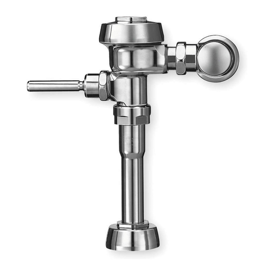
INSTALLATION INSTRUCTIONS FOR OPTIMA
ROYAL
EXPOSED WITH TRUE MECHANICAL OVERRIDE FLUSHOMETERS
®
MODEL 110/111
Unless otherwise noted, Sloan Valve Company warrants this product, manufactured and sold for commercial or industrial uses, to be free from defects in material and workmanship for a period of three (3)
years (one (1) year for special finishes, SF faucets, PWT electronics and 30 days for PWT software) from date of first purchase. During this period, Sloan Valve Company will, at its option, repair, replace, or
refund the purchase price of any product which fails to conform with this warranty under normal use and service. This shall be the sole and exclusive remedy under this warranty. Products must be returned
to Sloan Valve Company, at customer's cost. No claims will be allowed for labor, transportation or other costs. This warranty extends only to persons or organizations who purchase Sloan Valve Company's
products directly from Sloan Valve Company for purpose of resale. This warranty does not cover the life of the batteries.
THERE ARE NO WARRANTIES WHICH EXTEND BEYOND THE DESCRIPTION ON THE FACE HEREOF. IN NO EVENT IS SLOAN VALVE COMPANY
RESPONSIBLE FOR ANY CONSEQUENTIAL DAMAGES OF ANY MEASURE WHATSOEVER.
ROUGH-IN
MODEL 110/111/113/115/116
2-1/4"
(57 mm) 2-3/4"
(70 mm)
1-1/2"
(38 mm)
T.M.O.
TOP OF
FIXTURE
X VACUUM BREAKER SIZES VARIES
ON MODEL FROM TOP OF FIXTURE
TO C/L OF SUPPLY
MODEL 110/111 - 11½" (292 mm)
MODEL 113 - 23½" (597 mm)
MODEL 115 - 24" (610 mm)
MODEL 116 - 27" (686 mm)
‡ POSITION OF SENSOR BOX CAN BE RAISED OR LOWERED 1" (25 mm) IF IN CONFLICT WITH
HANDICAP GRAB BARS.
MODEL 186
LIMITED WARRANTY
4-3/4"
(121 mm)
1" I.P.S.
SUPPLY
(25 mm DN)
C L OF
SUPPLY
Y ‡
C L OF
ELEC.
BOX &
X
FIXTURE
Y SENSOR PLACEMENT VARIES
ON MODEL FROM TOP OF FIXTURE
TO BOTTOM OF SENSOR PLATE
MODEL 110/111 - 19" (483 mm)
MODEL 113 - 16" (406 mm)
MODEL 115 - 14" (365 mm)
MODEL 116 - 17" (432 mm)
SYSTEM SENSOR ACTIVATED
®
MODEL 180
2-1/4"
(57 mm)
MODEL 186
4"
(102 mm)
2-1/4"
(57 mm)
MODEL 180
4"
(102 mm)
Code No. 0816434
Rev. 5 (03/12)
Exposed Closet Flushometers
1-1/2" Top Spud
• Model 110/111 ES-S TMO
• Model 113 ES-S TMO
• Model 115 ES-S TMO
• Model 116 ES-S TMO
Exposed Urinal Flushometers
3/4" Top Spud
• Model 186 ES-S TMO
Exposed Urinal Flushometers
1-1/4" Top Spud
• Model 180 ES-S TMO
4-3/4"
C L OF
(121 mm)
ELEC.
(20 mm DN)
2-3/4"
(70 mm)
1-1/2"
(38 mm)
T.M.O. C L OF
SUPPLY
C L OF
FIXTURE
11-1/2"
(292 mm)
TOP OF
FIXTURE
1-1/2" (38 mm)
4-3/4"
C L OF
(121 mm)
ELEC.
(25 mm DN)
2-3/4"
(70 mm)
1-1/2"
(38 mm)
T.M.O. C L OF
SUPPLY
C L OF
FIXTURE
11-1/2"
(292 mm)
TOP OF
FIXTURE
1-1/2" (38 mm)
3/4" I.P.S.
SUPPLY
1" I.P.S.
SUPPLY
Advertisement
Table of Contents

Related Manuals for Sloan Royal Series


Summary of Contents for Sloan Royal Series
- Page 1 Unless otherwise noted, Sloan Valve Company warrants this product, manufactured and sold for commercial or industrial uses, to be free from defects in material and workmanship for a period of three (3) years (one (1) year for special finishes, SF faucets, PWT electronics and 30 days for PWT software) from date of first purchase. During this period, Sloan Valve Company will, at its option, repair, replace, or refund the purchase price of any product which fails to conform with this warranty under normal use and service.
- Page 2 CONNECTIONS. employs one (1) electrical box. Refer to rough-in illustrations for locations. Sloan flushometers are designed to operate with flowing pressure 15 NOTE: Install plaster ring so screw holes are on left and to 100 psi (104 to 689 kPa) of water pressure.
- Page 3 COUPLING BREAKER NOTE REPAIR KIT Max. adjustment of Sloan Adjustable Tailpiece is ½” (13 mm) IN or OUT from the standard 4¾” (121 mm) (C L of Valve to C L of Control Stop). VACUUM BREAKER FINISH If roughing-in measurement exceeds 5¼” (133 mm), consult factory for CONNECTION longer tailpiece.
- Page 4 6 - INSTALL SENSOR BOX MOUNTING PLATE Install Sensor Mounting Plate using the Screws provided. SENSOR BOX MOUNTING PLATE SENSOR MOUNTING PLATE ALT. MOUNTING HOLES IF MUD RING IS ATTACH SENSOR INSTALLED WITH MOUNTING PLATE TO HOLES ORIENTED PLASTER RING USING TOP/BOTTOM FOUR (4) SCREWS (SUPPLIED)
- Page 5 9 - INSTALL WALL FLANGE AND SECURE SOLENOID HOUSING AND COIL ASSEMBLY Connect transformer and sensor wire leads to coil wire leads. Locate flange on wall at dimensions shown. Lubricate O-Ring seal of solenoid assembly with water. C L OF FIXTURE While feeding wires back into the wall, carefully insert the F-15 FLANGE tail into the wall flange and install solenoid operator assembly to Flushometer.
- Page 6 Open control stop COUNTERCLOCKWISE one (1) FULL turn from the closed position. !!! IMPORTANT !!! All Sloan Flushometers are engineered for quiet operation. Excessive water flow creates noise, while too little water flow may not satisfy the needs of the fixture. Proper adjustment is made when plumbing fixture is cleansed after each flush without splashing water out from the lip AND a quiet flushing cycle is achieved.
- Page 7 I NDICATOR: T he red light flashes three (3) short flashes, three (3) long flashes then three (3) short flashes (“S-O-S”) and continues to repeat this cycle even when user When further assistance is required, please contact Sloan Technical Support at: steps out of the sensor’s detection range. 1-888-SLOAN-14 (1-888-756-2614)
- Page 8 P hone : 1-80 0-982-5 8 3 9 or 1 - 8 4 7 - 6 7 1 - 4 3 0 0 • F ax: 1 -8 0 0 - 44 7 -83 2 9 or 1 -8 47 -6 71 -4 38 0 • w w w .sloanval v e.c om © 2012 SLOAN VALVE COMPANY...
Need help?
Do you have a question about the Royal Series and is the answer not in the manual?
Questions and answers