Table of Contents
Advertisement
Quick Links
User Manual
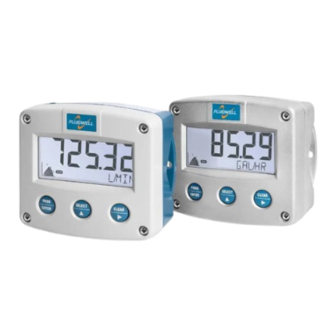
F014-P
FLOW RATE INDICATOR / TOTALIZER
WITH SCALED PULSE OUTPUT
Signal input:
pulse, NAMUR or coil flowmeter signal
Signal output:
one scaled pulse reflecting total
Options:
intrinsically safe
backlight
F-Series - Field mounted indicators for safe and hazardous areas
More info: www.fluidwell.com/fseries
Advertisement
Table of Contents

Related Manuals for Fluidwell F014


Summarization of Contents
About This Manual
How to Use This Manual
Guide on how to effectively use the user manual.
Use of Pictograms
Explanation of symbols used in the manual to convey important safety information.
Warranty and Technical Support
Information on product warranty and how to obtain technical support.
Model Reference
Details about the specific model and its versions.
Safety
Personal Safety
Critical safety precautions for handling and operating the device to prevent injury.
End-User Responsibilities
Outlines the duties and responsibilities of the end-user regarding installation and use.
Potential Equipment Damage
Information on actions that could lead to damage to the equipment.
Disposal of Electronic Waste
Guidelines for the environmentally responsible disposal of the electronic product.
Introduction
System Description
Overview of the F014-P as a microprocessor-driven flow rate indicator and totalizer.
Product Features
Highlights the key characteristics and capabilities of the F014-P device.
Installation Example
Illustrates a typical physical installation scenario for the F014-P with a flowmeter.
Operation
Introduction
Introduction to the chapter detailing daily use and operation of the F014-P.
Operating Modes
Description of the different operational modes (Operator, Setup, Program) for the device.
Control Panel
Details the physical control panel, including the LCD display and function keys.
Display
Explains the information presented on the F014-P's LCD screen during operation.
Displayed Information
Describes how process information, units, and status are shown on the display.
Operator Alarms
Covers the types of alarms the operator might encounter, such as low battery.
Low Battery
Specifics on the low battery warning icon and its implications for continued operation.
Internal Error
Information on how to handle and interpret internal error messages displayed by the unit.
Configuration
Introduction
Introduction to configuring the F-Series for optimal functionality using front keys.
Configuring Using Setup Mode
Guide on how to enter and navigate the device's setup menu for configuration.
Entering Setup Mode
Step-by-step instructions on how to access the device's setup mode.
Navigating the Setup Menu
Explains how to move through menu groups and items using the control keys.
Changing Configuration Settings
Detailed procedure for modifying configuration values and selections within the setup menu.
Returning to Operator Mode
Instructions on how to exit the setup mode and return to normal operation.
Setup Menu Overview
A comprehensive table listing all configurable settings, their defaults, and options.
Setup Menu Explanations
Detailed explanations for each menu item found in the setup overview.
Installation
Installation / Environmental Conditions
Guidelines for environmental conditions and suitability for safe or hazardous areas.
Handling the F014-P Enclosure
Procedures for safely handling the device's enclosure, including identification labels.
Identification
How to identify the F-Series device using external and internal labels.
Opening, Assembling and Closing the F-Series
Step-by-step guide for opening and reassembling the device enclosure.
Mechanical Installation
Information related to the physical mounting and dimensions of the device.
Mechanical Dimensions
Technical drawings showing the dimensions of various enclosure types.
Mounting the F-Series
Different methods and configurations for mounting the F014-P enclosure.
Electrical Installation
General information and precautions for the electrical installation of the device.
Electrical Safety
Essential safety guidelines for electrical connections and installations.
Protective Earth (PE) Connections
Instructions for properly connecting the protective earth ground for safety.
Field Wiring Connections
Details on making field wiring connections and complying with regulations.
Power Supply
Information on the different power supply options and requirements for the device.
Sensor Supply
Details on the sensor supply voltage options available for different device types.
Terminal Connectors Safe Area Applications - Type PX, PD
Specific terminal connector information for PX and PD type devices in safe areas.
Terminal Connectors Safe Area Applications - Type PF, PM
Specific terminal connector information for PF and PM type devices in safe areas.
Intrinsically Safe Applications
Identification
Guidance on identifying intrinsically safe devices using specific labels and markings.
Electrical Installation in Hazardous Areas
Detailed safety and installation instructions for hazardous area environments.
Installations Based on FM or CSA Certificate
Installation requirements specific to FM or CSA certified hazardous area applications.
Electrical Data - Control Drawing
Critical electrical data and control drawings for intrinsically safe installations.
Installations Based on ATEX or IECEx Certificate
Installation guidelines compliant with ATEX and IECEx directives for hazardous areas.
Electrical Data - Annex 1
Annex containing specific electrical data and parameters for intrinsically safe circuits.
Power Supply
Power supply considerations for intrinsically safe applications, including battery options.
Sensor Supply
Information on sensor supply voltage for intrinsically safe configurations.
Terminal Connectors Hazardous Area Applications
Overview of terminal connectors for intrinsically safe F014-P Type XI in hazardous areas.
Configuration Examples Intrinsically Safe Applications
Practical examples of configuration for intrinsically safe applications.
F014-P-(OT)-PC-(PX)-XI-(ZB) Battery Powered - Ex ia IIC/IIIC
Configuration example for a battery-powered, intrinsically safe application.
F014-P-OT-PX-XI-(ZB) - Ex ia IIC/IIIC
Configuration example for a specific intrinsically safe setup with PX power.
F014-P-OT-PX-XI-ZB - Ex ia IIC/IIIC
Another configuration example for an intrinsically safe setup with PX power.
F014-P-OT-PD-XI-ZB - Ex ia IIC/IIIC
Configuration example for an intrinsically safe setup using PD power supply.
Maintenance
General Directions
General guidance and precautions for performing maintenance on the instrument.
Instructions for Repair
Procedure for handling product repairs, emphasizing that user repair is not possible.
Battery Replacement
Detailed instructions and safety precautions for replacing the device's battery.
Safety Instructions
Crucial safety warnings and guidelines specific to handling and replacing batteries.
Battery Replacement Procedure
Step-by-step process for safely removing and installing the battery.
Disposal of Batteries
Guidelines for the proper and environmentally sound disposal of used batteries.
Appendix A - Technical Specification
General
General technical specifications including display type, dimensions, and enclosure details.
Input
Technical specifications related to the device's input signals, such as flowmeter types and frequency.
Output
Technical specifications for the device's output signals, including pulse output types and capabilities.
Operational Functions
Specifications for operator functions, displayed information, and total/flow rate parameters.
Appendix C - Legal Information
Declarations of Conformity
Official declarations confirming the product's compliance with relevant directives and standards.
Need help?
Do you have a question about the F014 and is the answer not in the manual?
Questions and answers