Table of Contents
Advertisement
Quick Links
Advertisement
Table of Contents

Related Manuals for Fluidwell F012


Summarization of Contents
About This Manual
How to Use This Manual
Explains the manual's structure, intended audience, and safety information.
Use of Pictograms
Explains the meaning of warning and caution symbols used in the manual.
Warranty and Technical Support
Provides contact information for product warranty and technical assistance.
Model Reference
Lists hardware/software versions and document details for product identification.
Safety
Personal Safety
Outlines crucial safety precautions for operating the unit, including explosion and shock hazards.
End-User Responsibilities
Defines responsibilities for installation, use, servicing, and compliance with guidelines.
Potential Equipment Damage
Details risks that can cause damage to the unit or connected equipment, like ESD.
Disposal of Electronic Waste
Provides guidelines for environmentally responsible disposal of the product.
Introduction
System Description
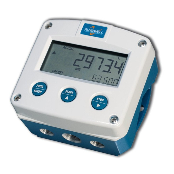
Describes the F012-P as a microprocessor-driven flow rate indicator and totalizer.
Product Features
Lists general characteristics, configuration options, and input capabilities of the F012-P.
Installation Example
Illustrates the F012-P in a typical installation with labeled components.
Operation
Introduction
Introduces the chapter on the daily use and operation of the F012-P.
Operating Modes
Describes the available operating modes: OPERATOR, SETUP, and PROGRAM.
Control Panel
Details the LCD display and the function of the PROG/ENTER, SELECT, and CLEAR keys.
Display
Explains the display layout, information shown, and symbols used.
Backlight (Type ZB)
Explains the function, control, and intensity adjustment of the optional display backlight.
Displayed Information
Describes how flow rate, total, and accumulated total are displayed.
Flow Rate and Total or Flow Rate
Details display of flow rate and total, units, and trend indicators.
Clear Total
Explains the procedure to re-initialize the resettable total value.
Accumulated Total
Describes the display and non-resettable nature of the accumulated total.
Operator Alarms
Details operator alarms, including low battery warnings.
Low Battery
Explains the low battery warning icon and its implications for battery replacement.
Internal Error
Describes how to handle internal errors and locate error codes for troubleshooting.
Configuration
Introduction
Introduces the chapter on configuring the F-Series for optimal functionality.
Configuring Using Setup Mode
Explains how to enter and navigate the SETUP menu for configuration.
Entering Setup Mode
Provides step-by-step instructions to enter the device's SETUP mode.
Navigating the Setup Menu
Explains the menu structure and navigation using the device's keys.
Changing Configuration Settings
Details the procedure for changing values and selections within the SETUP menu.
Returning to Operator Mode
Explains how to exit SETUP mode and return to the normal OPERATOR mode.
Setup Menu Overview
Provides a table overview of all configuration settings and their default values.
Setup Menu Explanations
Detailed explanations for each menu group and item.
Menu 1: Total
Explains configuration settings for Total, including K-factor calculations.
Menu 2: Flow Rate
Explains configuration settings for Flow Rate, including K-factor calculations.
Menu 3: Display
Explains display settings such as Function, Backlight, and Brightness.
Menu 4: Power Management
Details settings for LCD update rate and battery mode.
Menu 5: Flowmeter
Explains settings for signal type selection and flowmeter characteristics.
Menu 6: Others
Covers settings for model, software version, serial number, pass code, and tag number.
Installation
Installation / Environmental Conditions
Details installation types (Safe/Hazardous Area) and environmental operating limits.
Handling the F012-P Enclosure
Provides guidance on handling the device enclosure during installation.
Identification
Explains how to identify the unit using external and internal identification labels.
Opening, Assembling and Closing the F-Series
Provides a step-by-step procedure for opening and closing the device enclosure.
Mechanical Installation
Covers mechanical aspects of installation, including mounting.
Mechanical Dimensions
Shows detailed dimensions for various aluminum and stainless steel enclosures.
Mounting the F-Series
Illustrates various mounting configurations for the F-Series device.
Hazardous Area Installations
General information on electrical installation requirements for hazardous areas.
Electrical Safety
General remarks on electrical safety, wiring practices, and grounding.
Protective Earth (PE) Connections
Explains how to properly connect Protective Earth to enclosures.
Field Wiring Connections
Details field wiring connection requirements and compliance standards.
Power Supply
Describes available power supply types and their specific requirements.
Sensor Supply
Details sensor supply options available for different device types.
Terminal Connectors Safe Area Applications - Type PX, PD
Overview of terminal connectors for PX and PD types in safe area applications.
Terminals 1-3 (6): Flowmeter Input
Explains connections for flowmeter input signals (coil, NPN, PNP) on PX/PD types.
Terminals 4-5: Power Supply - Type PX and PD
Details power supply connections for PX and PD types on terminals 4-5.
Terminal 6: Sensor Power Supply - Type PD
Explains the sensor power supply connection for Type PD at terminal 6.
Terminals 9-10: Backlight Power Supply - Type ZB
Details backlight power supply connections for Type ZB at terminals 9-10.
Terminal Connectors Safe Area Applications - Type PF, PM
Overview of terminal connectors for PF and PM types in safe area applications.
Terminals GND-1-2: Power Supply
Details power supply connections for PF and PM types on GND, 1, and 2 terminals.
Terminals 5-7: Flowmeter Input
Explains flowmeter input connections for PF/PM types (coil, NPN, PNP) on terminals 5-7.
Intrinsically Safe Applications
Identification
Explains identification labels for intrinsically safe units for hazardous areas.
Electrical Installation in Hazardous Areas
General information and specific precautions for electrical installation in hazardous areas.
Installations Based on FM or CSA Certificate
Specific installation instructions for devices certified under FM or CSA.
Electrical Data - Control Drawing
Provides essential electrical data and parameters for intrinsically safe applications.
Installations Based on ATEX or IECEx Certificate
Specific installation instructions for devices certified under ATEX or IECEx.
Electrical Data - Annex 1
Annex containing detailed electrical data for intrinsically safe circuits.
Power Supply
Details power supply options and requirements for intrinsically safe applications.
Sensor Supply
Explains the limited sensor supply options for intrinsically safe applications.
Terminal Connectors Hazardous Area Applications
Overview of terminal connectors for hazardous area applications.
Configuration Examples Intrinsically Safe Applications
Provides practical examples of configuration for intrinsically safe applications.
F012-P-PC-(PX)-XI-(ZB) Battery Powered - Ex ia IIC/IIIC
Configuration example for a battery-powered, intrinsically safe application.
F012-P-PX-XI-(ZB) - Ex ia IIC/IIIC
Configuration example for a PX-powered, intrinsically safe application.
F012-P-PX-XI-ZB - Ex ia IIC/IIIC
Configuration example for a PX-powered, intrinsically safe application with ZB backlight.
F012-P-PD-XI-ZB - Ex ia IIC/IIIC
Configuration example for a PD-powered, intrinsically safe application with ZB backlight.
Maintenance
General Directions
Provides general guidelines for maintenance, periodic checks, and cleaning.
Instructions for Repair
States that repairs must be performed by the manufacturer or authorized agents only.
Battery Replacement
Details safety instructions and considerations for replacing the device battery.
Safety Instructions
Crucial safety precautions for handling and replacing batteries, especially in hazardous areas.
Battery Replacement Procedure
Step-by-step instructions for safely removing and installing the unit's battery.
Disposal of Batteries
Guidelines for the proper disposal of used batteries according to regulations.
Appendix A - Technical Specification
General
Provides general specifications for the display and enclosure types.
Input
Details flowmeter signal types, frequency, K-factor, and low-pass filter options.
Operational
Lists operator functions like displayed information, units, and reset total.
Appendix B - Troubleshooting
Install and Configuration Errors
Describes common installation and configuration errors and their possible causes.
Internal Alarms
Lists internal alarm codes, their explanations, and recommended actions.
Appendix C - Legal Information
EU Declaration of Conformity
Contains the EU Declaration of Conformity for the F0-Series indicators.
UKCA Declaration of Conformity
Contains the UKCA Declaration of Conformity for the F0-Series indicators.
Need help?
Do you have a question about the F012 and is the answer not in the manual?
Questions and answers