Table of Contents
Advertisement
Quick Links
User Manual
F018-P
FLOW RATE MONITOR / TOTALIZER
WITH LINEARIZATION, HIGH/LOW FLOWRATE ALARMS,
SCALED PULSE OUTPUT, ANALOG OUTPUT
and HART communication
Signal input:
pulse, NAMUR or coil flowmeter signal
Signal output:
one analog reflecting flowrate
and one flow rate alarm
or scaled pulse reflecting accumulated total
Options:
intrinsically safe
backlight
HART communication
F-Series - Field mounted indicators for safe and hazardous areas
More info: www.fluidwell.com/fseries
Advertisement
Table of Contents

Related Manuals for Fluidwell F018-P


Summary of Contents for Fluidwell F018-P
- Page 1 NAMUR or coil flowmeter signal Signal output: one analog reflecting flowrate and one flow rate alarm or scaled pulse reflecting accumulated total Options: intrinsically safe backlight HART communication F-Series - Field mounted indicators for safe and hazardous areas More info: www.fluidwell.com/fseries...
-
Page 2: Table Of Contents
Menu 8: Pulse output ..................... 21 5.4.9 Menu 9: Others ......................21 INSTALLATION........................22 Installation / environmental conditions ................22 Handling the F018-P enclosure ..................23 6.2.1 Identification........................23 6.2.2 Opening, assembling and closing the F-Series .............. 24 Mechanical installation....................25 6.3.1... - Page 3 Power supply ........................41 7.3.2 Sensor supply ......................... 42 Configuration examples Intrinsically Safe applications ........... 42 7.4.1 F018-P-AH-CR-OT-PX-XI-(ZB) - Ex ia IIC/IIIC ............... 42 7.4.2 F018-P-AH-CR-OT-PX-XI-ZB - Ex ia IIC/IIIC ..............43 7.4.3 F018-P-AH-CR-OT-PD-XI-ZB - Ex ia IIC/IIIC ..............43 MAINTENANCE........................
-
Page 4: About This Manual
● incorrect functioning of the unit or connected instruments. A note informs you of important information. WARRANTY AND TECHNICAL SUPPORT For warranty and technical support on your Fluidwell products, visit our internet site www.fluidwell.com or contact us at support@fluidwell.com. MODEL REFERENCE Hardware version: 03.04.xx... -
Page 5: Safety
F018-P User Manual SAFETY PERSONAL SAFETY ● Explosion hazard: Never open the unit when explosive atmosphere is present, and the unit is connected to a power supply or consuming device like the internal battery supply. ● Risk of electric shock: Only open the unit if all leads are free of potential electrical energy. -
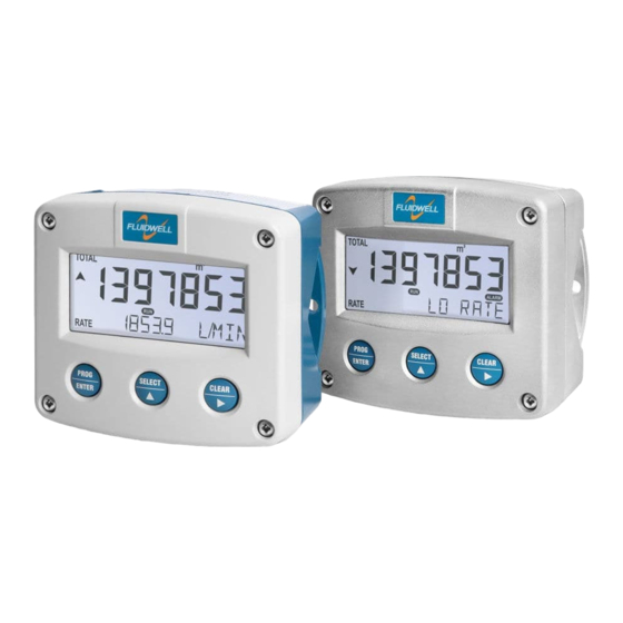
Page 6: Introduction
Fig. 1: The F018 This manual describes the daily use, configuration and installation of the F018-P with pulse input from a flowmeter and its available options. The following figure shows the F018-P used in a typical application. -
Page 7: Input
● Several options are available for powering the sensor. 3.2.3 OUTPUT ● A pulse output is available from the F018-P, reflecting the passing of a programmable quantity or the presence of an alarm. ● An analog output (4 - 20 mA) reflecting the linearized flow rate is available. -
Page 8: Operation
Section 2: Safety [»5] INTRODUCTION This chapter describes the daily use and operation of the F018-P. For this, the F-Series is equipped with a control panel that provides the operator with various functions, information and operating modes. 4.1.1... -
Page 9: Backlight (Type Zb)
F018-P User Manual Normally, the display is updated depending on the refresh rate selected in the configuration settings. By pressing any key, the display switches to refreshing the information 8 times per second. After 30 seconds of key inactivity, the display returns to the configured refresh rate. -
Page 10: Operator Alarms
User Manual F018-P PROGRAM Fig. 5: Example of display information during programming minimum flow rate alarm level When a value was changed but ENTER has not been pressed, the change can be canceled by waiting for 20 seconds or by pressing ENTER and holding for three seconds. -
Page 11: Configuration
INTRODUCTION This chapter describes how technicians can use configuration settings to configure the F-Series for optimal functionality. Configuration of the F018-P can be done in SETUP mode, using the front keys. CONFIGURING USING SETUP MODE For an overview of Operating modes, see Section 4.1.1: Operating modes [»8]... -
Page 12: Changing Configuration Settings
User Manual F018-P 5.2.3 CHANGING CONFIGURATION SETTINGS A menu item either contains a value (a number with optionally a decimal point and sign, e.g. -123.45) or a selection list (e.g. L – m - USGAL). After a menu item is selected in the SETUP menu, a new value can be programmed by performing the following steps. -
Page 13: Setup Menu Overview
F018-P User Manual SETUP MENU OVERVIEW TOTAL DEFAULT UNIT L - m3 - kg - lb - GAL - USGAL - bbl - no unit DECIMALS 0 - 3 0.000010 - 9,999,999 K-FACTOR DECIMALS K-FACTOR 0 - 6 FLOW RATE... -
Page 14: Setup Menu Explanations
User Manual F018-P ANALOG OUTPUT DEFAULT PV LRV -999,999 ... 999,999 PV URV -999,999 ... 999,999 1600 LOOP CURRENT Enabled - disabled Enabled MODE LOOP TEST Off - set 4 mA - set 20 mA TUNE LO 0000 - 9999... -
Page 15: Menu 2: Flow Rate
F018-P User Manual TOTAL K-FACTOR This value is used to convert the flowmeter pulse signals into a Total. The K-Factor is based on the number of pulses generated by the flowmeter per measurement unit selected in 1.1: TOTAL > UNIT Accuracy of the measurement system depends on the accuracy of the K-factor. -
Page 16: Menu 3: Alarm
255. The lower the number of pulses, the higher the power consumption of ● the F018-P will be (important for battery powered applications). For low frequency applications (below 10 Hz), do not program more ●... -
Page 17: Menu 4: Display
With this setting, the optional backlight can be turned on or off. BACKLIGHT ALARM If the F018-P generates an alarm, the backlight can be set to change to red. The following settings are available: OFF: during an alarm the color is white. -
Page 18: Menu 5: Flowmeter
5.4.5 MENU 5: FLOWMETER FLOWMETER SIGNAL Selects the type of input sensor pickup / signal. The F018-P can process several types of input signal. The settings with LP are used to apply a built-in low-pass filter. FLOWMETER SELECTION CHARACTERISTICS TYPE OF SIGNAL... - Page 19 F018-P User Manual K-Factor KF0=51.64178 MF1=0.691300 KF1=35.7 @ 64Hz. KF2=47.5 @ 93Hz. MF2=0.919798 MF3=1.041792 KF3=53.8 @ 161Hz. KF4=49.2 @ 336Hz. MF4=0.952717 KF5=52.9 @ 514Hz. MF5=1.024364 51.6 35.7 Frequency 64 93 10,000 Fig. 8: Example of K-Factors and linearization points When a new frequency is measured, the corresponding Meter Factor is calculated by interpolating between the linearization points.
-
Page 20: Menu 7: Analog Output
User Manual F018-P LINEARIZATION DECIMALS Determines the number of decimals for the frequency entered at FREQUENCY . The following can be selected: 6.1..F: LINEARIZATION > FREQ. / M-FACTOR 1..15 00000 – 1111.1 – 222.22 – 33.333 5.4.7 MENU 7: ANALOG OUTPUT An analog 4-20 mA signal is generated according to the flowrate. -
Page 21: Menu 8: Pulse Output
F018-P User Manual 5.4.8 MENU 8: PULSE OUTPUT PULSE OUTPUT PULSE WIDTH The pulse width determines the time that the output will be active, that is, the duration of the pulse. The minimum period between pulses is equal to the pulse length (a duty cycle of 50% or less). The pulse width is set in milliseconds in the range 0.001 –... -
Page 22: Installation
Personnel must read and understand this Operating Manual before carrying out its instructions. ● The F018-P may only be operated by personnel who are authorized and trained by the operator of the facility. All instructions in this manual are to be observed. -
Page 23: Handling The F018-P Enclosure
F018-P User Manual HANDLING THE F018-P ENCLOSURE 6.2.1 IDENTIFICATION The F-Series can be supplied as suitable for Safe Area or Hazardous Area. Suitability for Intrinsic Safety is indicated in the model Type XI. Refer to for identification and installation labels Section 7: Intrinsically safe applications [»36]... -
Page 24: Opening, Assembling And Closing The F-Series
User Manual F018-P Serial number and year of production The serial number can be reviewed on the identification label, the installation label, or in . The production SETUP 9.3: OTHERS > SERIAL NUMBER date is shown on the label and also indicated by the first 4 digits of the serial number representing year and week number (YYWW). -
Page 25: Mechanical Installation
F018-P User Manual MECHANICAL INSTALLATION 6.3.1 MECHANICAL DIMENSIONS Aluminum and stainless steel enclosures 75 mm (2.95") 90 mm (3.54") 130 mm (5.12") 112 mm (4.40") 12mm 12mm 30 mm 30 mm 30mm 30mm M16 x 1,5 M16 x 1,5 M20 x 1,5... - Page 26 User Manual F018-P Non-metallic enclosures 75 mm (2.95") 130 mm (5.12") 112 mm (4.40") HK back box: (flat bottom) 75 mm (2.95") 118 mm (4.65”) 25mm 25mm D=20mm D=20mm 12mm 12mm 30mm 30mm 24mm 24mm D=12mm D=16mm D=16mm D=20mm 36mm 36mm 0.12”...
-
Page 27: Mounting The F-Series
F018-P User Manual 6.3.2 MOUNTING THE F-SERIES The enclosure can be installed by itself or with the aid of a mounting plate in the configurations shown below. When the product is installed on a wall or onto a meter, please use components and installation techniques that are suitable for the used materials. -
Page 28: Electrical Installation
● The wire screens shall be terminated at one side to prevent wire loops. Inside of the F018-P, the different common ground terminals are connected to each other. It is advised, as illustrated, to terminate the wire screens in the vicinity of the sensor and to insulate the wire screen with a shrink tube at the F018-P side. -
Page 29: Field Wiring Connections
User Manual Connecting Protective Earth to a non-metallic enclosure When the F018-P is supplied with a non-metal enclosure (e.g. plastic), the field mount enclosure meets the requirements of class 2 (double insulated). Therefore any incoming PE conductor can be terminated with an insulating end cap. -
Page 30: Power Supply
C22.2 No. 61010-1 / UL61010-1 / EN/IEC 61010-1. The F018-P can be powered from an external power supply. For Type PX or PD, an optional internal power supply is also available in the form of a lithium battery (Type PB). When both external and internal power supplies are available, the internal power supply is interrupted and will act as a backup supply. -
Page 31: Terminals 1-3 (6): Flowmeter Input
To configure the sensor supply, see for details. Section 6.4.5: Sensor supply [»30] Coil The F018-P is suitable for use with flowmeters with a coil output signal. Two sensitivity levels can be selected with the SETUP-function ( SETUP 5.1: FLOWMETER > SIGNAL [»18] ●... - Page 32 Terminals 1 - 2: NPN signal input The F018-P is suitable for use with flowmeters with a PNP output signal. Terminal 3 offers 3.2V which has to be switched by the sensor to terminal 2 (SIGNAL). For a reliable pulse detection, the pulse amplitude has to go above 1.2V.
- Page 33 Terminals 1 - 2 and 6: Active signal Reed switch The F018-P is suitable for use with flowmeters with a reed switch. To avoid pulse bounce from the reed-switch, it is advised to select REED LP - low-pass filter ( SETUP 5.1: FLOWMETER >...
-
Page 34: Terminals 4-5: Power Supply - Type Px And Pd
TERMINALS 4-5: POWER SUPPLY - TYPE PX AND PD To power the F018-P a 8-30V DC (type PX) or 16-30V DC (type PD) power supply can be applied. Connect the "-" to terminal 4 and the "+" to terminal 5. -
Page 35: Terminals 11-12: Analog Output + Output Loop Power - Type Ah
Fig. 25: Terminals 11-12: Isolated passive 4-20 mA signal – Type AH 6.5.7 TERMINALS 11-12: HART COMMUNICATION - TYPE CR The F018-P Type CR is suitable for connecting a HART Master device to terminals 11 and 12. optional resistor MASTER Fig. 26:... -
Page 36: Intrinsically Safe Applications
User Manual F018-P INTRINSICALLY SAFE APPLICATIONS IDENTIFICATION The F0-Series can be supplied as suitable for Safe Area or Hazardous Area. Suitability for Intrinsic Safety is indicated in the model Type XI. If Type XI is not indicated your unit is not suitable for Intrinsically Safe applications! -
Page 37: Electrical Installation In Hazardous Areas
Personnel must read and understand this Operating Manual before carrying out its instructions. ● The F018-P may only be operated by personnel who are authorized and trained by the operator of the facility. All instructions in this manual are to be observed. -
Page 38: Electrical Data - Control Drawing
User Manual F018-P 7.2.2 ELECTRICAL DATA - CONTROL DRAWING trol Dr ing F -P-XI Ce t r ific t a ion F0-SERIES – Type -XI T RMINAL CONNE CTORS F0 ERIE c mm on ground Ce tif r ica e number: CSA.08.2059461... -
Page 39: Installations Based On Atex Or Iecex Certificate
F018-P User Manual 7.2.3 INSTALLATIONS BASED ON ATEX OR IECEX CERTIFICATE Installation instructions ● For installation under ATEX directive: this Intrinsically Safe device must be installed in accordance with ATEX directive 2014/34/EU and product certificate KEMA 03ATEX1168 X. ● For installation under IECEx scheme: this Intrinsically Safe device must be installed in accordance with product certificate IECEx DEK 08.0006X. -
Page 40: Electrical Data - Annex 1
User Manual F018-P 7.2.4 ELECTRICAL DATA - ANNEX 1 Annex 1 ( mo el p s eci fic) to prod uct certif c i ates KEMA 03ATEX1168 X, IECEx DEK 08. 00 6 X Model F0..-P-XI Int nal supply for use w... -
Page 41: Terminal Connectors Hazardous Area Applications
7.3.1 POWER SUPPLY The F018-P can be powered from an external power supply. For Types PX or PD, an optional internal power supply is also available in the form of an intrinsically safe lithium primary battery (Type PC). When both external and internal power supplies are available, the internal power supply is interrupted and will serve as a backup supply. -
Page 42: Sensor Supply
Sensor supply voltage on Terminal 3: 1.2-3.2V DC. Please note: Type PX may be used in combination with the battery (Type PC). PX will power the F018-P, the battery will be disabled automatically until the power is disconnected Page 42... -
Page 43: F018-P-Ah-Cr-Ot-Px-Xi-Zb - Ex Ia Iic/Iiic
F018-P-AH-CR-OT-PX-XI-ZB - Ex ia IIC/IIIC - Intrinsically Safe application Please note: Type PX may be used in combination with the battery (Type PC). PX will power the F018-P, the battery will be disabled automatically until the power is disconnected. 7.4.3... -
Page 44: Maintenance
Personnel must read and understand this Operating Manual before carrying out its instructions. ● The F018-P may only be operated by personnel who are authorized and trained by the operator of the facility. All instructions in this manual are to be observed. -
Page 45: Battery Replacement
F018-P User Manual BATTERY REPLACEMENT 8.3.1 SAFETY INSTRUCTIONS ● Handle the battery with the utmost care to prevent a short circuit and damage. A mistreated battery can become unsafe. Unsafe batteries can cause serious injury. Do not recharge, crush, disassemble, incinerate, heat above its rated temperature or expose the contents to water. -
Page 46: Battery Replacement Procedure
User Manual F018-P 8.3.2 BATTERY REPLACEMENT PROCEDURE Before starting the battery replacement procedure, make sure that the marking on the new battery corresponds with the type of installation, as shown in Section 8.3.1: Safety instructions [»45] Remove the old battery as follows: 1. -
Page 47: Appendix A - Technical Specification
F018-P User Manual APPENDIX A - TECHNICAL SPECIFICATION GENERAL DISPLAY Type High intensity reflective numeric and alphanumeric LCD, UV-resistant Digits 7 with height 17mm (0.67”) and 11 with height 8mm (0.31”). Various symbols and measuring units. Dimensions 90 x 40 mm (3.5” x 1.6”) - Page 48 User Manual F018-P POWER REQUIREMENTS Type PB SAFE AREA ONLY - Standard lithium primary battery. Life up to 5 years. Type PC INTRINSICALLY SAFE - Certified lithium primary battery. Life up to 5 years. Type PD 16-30 V DC. Max power consumption 1 W.
-
Page 49: Input
F018-P User Manual INPUT FLOWMETER Signal type Coil / sine wave (min. 20 mVpp or 90 mVpp - sensitivity selectable), NPN, PNP, open collector, reed switch, NAMUR, active pulse signals. Type ZF Minimum coil sensitivity 10 mVpp Type ZG Minimum coil sensitivity 5 mVpp... - Page 50 User Manual F018-P FLOW RATE Digits 7 digits Unit L/min - L/hr - m3/sec - m3/min - m3/hr - m3/day - g/sec - g/min - g/hr - kg/sec - kg/min - kg/hr - kg/day - ton/min - ton/hr - ton/day - GAL/sec - GAL/min - GAL/hr - GAL/day - bbl/sec - bbl/min -...
-
Page 51: Appendix B - Troubleshooting
APPENDIX B - TROUBLESHOOTING Table 1 lists and describes how to troubleshoot problems that can occur when installing or operating the F018-P. Table 2 lists internal alarm codes and conditions signaled by a blinking ALARM flag on the display ). Press the SELECT key several times to display the 4-digit error code shown in Table 2. -
Page 52: Appendix C - Hart Communication
All standard HART configuration items are accessible without any special configuration. To configure all settings of your F018-P HART device, your host or communicator must use a specific HART Device Descriptor (DD), especially designed for the F018. These DD’s can be downloaded from the FieldComm Group website (www.fieldcommgroup.org) or the Fluidwell website (www.fluidwell.com). - Page 53 F018-P User Manual DEVICE STATUS INFORMATION Byte Description Content Error register 14.0 Display error 14.1 Eeprom error 14.2 Not used 14.3 Not used 14.4 Low alarm error 14.5 High alarm error 14.6 Linearization error 14.7 Input frequency too high Bit 14.0 and 14.1 are critical errors.
- Page 54 User Manual F018-P FLOW RATE (volume) F018-P HART F018-P HART l/sec gal/hr gal/h l/min l/min gal/day gal/d l/hr bbl/sec bbl/s m3/sec cum/sec bbl/min bbl/min m3/min cum/min bbl/hr bbl/h m3/hr cum/h bbl/day bbl/d m3/day cum/d cf/sec cuft/s gal/sec gal/s cf/min cuft/min...
-
Page 55: Appendix D - Legal Information
DECLARATIONS OF CONFORMITY EU De cla tio n of Conformi Fluidwell F0‒Series indicators he , February 2022 We, Fluidwell BV, declare under our s e ol respons ibility that the F0 ‒Series indicators are de igne d and will operate conform the following applicable European... - Page 56 User Manual F018-P LIST OF CONFIGURATION SETTINGS SETTING DEFAULT DATE: DATE: TOTAL UNIT DECIMALS K-FACTOR DECIMALS K-FACTOR FLOW RATE UNIT L/min DECIMALS K-FACTOR DECIMALS K-FACTOR CALCULATION CUT-OFF DAMPING ALARM ALARMSET Operate FLOWZERO default ALARM LOW ALARM HIGH DELAY ALARM LOW...
- Page 57 F018-P User Manual LINEARIZATION FREQ. / M-FACTOR 1 0.0 Hz 1.000000 FREQ. / M-FACTOR 2 0.0 Hz 1.000000 FREQ. / M-FACTOR 3 0.0 Hz 1.000000 FREQ. / M-FACTOR 4 0.0 Hz 1.000000 FREQ. / M-FACTOR 5 0.0 Hz 1.000000 FREQ. / M-FACTOR 6 0.0 Hz...
- Page 58 User Manual F018-P OTHERS TYPE / MODEL F018-P SOFTWARE VERSION 03.xx.xx SERIAL NUMBER xxxxxxx PASS CODE 0000 POLL ADRESS TAG NUMBER 0000000 Page 58 FW_F018-P_M_v0501-01_EN...
- Page 59 F018-P User Manual NOTES FW_F018-P_M_v0501-01_EN Page 59...
- Page 60 Fluidwell bv P.O. Box 6 Voltaweg 23 Website: www.fluidwell.com 5460 AA Veghel 5466 AZ Veghel Find your nearest representative: www.fluidwell.com/representatives the Netherlands the Netherlands © Copyright 2022 - FW_F018-P_M_v0501-01_EN...
Need help?
Do you have a question about the F018-P and is the answer not in the manual?
Questions and answers